Competition between ferromagnetic and charge-orbital ordered
phases
in Pr1-xCaxMnO3 for =1/4, 3/8, and 1/2
Abstract
Spin, charge, and orbital structures in models for doped manganites are studied by a combination of analytic mean-field and numerical relaxation techniques. At realistic values for the electron-phonon and antiferromagnetic spin couplings, a competition between a ferromagnetic (FM) phase and a charge-orbital ordered (COO) insulating state is found for =1/4, 3/8, and 1/2, as experimentally observed in Pr1-xCaxMnO3 for =0.30.5. The theoretical predictions for the spin-charge-orbital ordering pattern are compared with experiments. The FM-COO energy difference is surprisingly small for the densities studied, result compatible with the presence of a robust colossal-magnetoresistive effect in Pr1-xCaxMnO3 in a large density interval.
pacs:
PACS numbers: 75.30.Kz, 75.50.Ee, 75.10.-b, 75.15.-mThe explanation of the colossal magnetoresistance (CMR) phenomenon in perovskite manganese oxides is currently one of the most challenging problems in condensed matter physics.[1] In addition to their unusual magneto-transport properties, manganites present a very rich phase diagram involving phases with spin, orbital, and charge order. Early investigations of these materials relied on the “double-exchange” (DE) mechanism for ferromagnetism, in which electrons optimize their kinetic energy if the spins background is polarized. However, this simple picture is not sufficient to rationalize the CMR effect since the properties of the insulating state involved in the metal-insulator transition play a key role. In fact, the understanding of the A-type antiferromagnetic (AFM) insulator LaMnO3 requires a two orbital model and strong electron-phonon or Coulomb interactions to induce the complex spin and orbital arrangement characteristic of this state.[2] The evolution of the undoped phase with light hole doping, and its eventual transformation into a ferromagnetic (FM) metal,[3] is nontrivial and it is expected to proceed through a mixed phase process involving nanometer domains.[4] The conspicuous percolative characteristics of the transition have been recently explained by the influence of quenched disorder in the hopping and exchanges of manganite models.[5]
At high hole densities near =1/2 a strong CMR phenomenon occurs.[6] For example, in Nd1/2Sr1/2MnO3,[7] a low magnetic field of a few Teslas is enough to induce a metal insulator transition between the FM metallic and charge-ordered (CO) insulating phases. Based on recent computational studies at =1/2, that clearly showed the presence of a first-order level-crossing transition between the FM and CE-type CO states,[8] a simple picture to explain this result can be constructed. At densities slightly above the critical hole doping 1/2 of the FM-CO transition it is reasonable to expect that small magnetic fields will transform the ground state from CO to FM, since these states are close in energy. However, the FM metallic and CO insulating phases have a quadratic and linear dependence with , respectively, and small magnetic fields will become rapidly ineffective to produce such a transition as grows away from . Thus, in this simple scenario the CMR effect can only occur in a narrow density window around . Unfortunately, some experiments suggest that this scenario is incomplete. In fact, it is well-known that for Pr1-xCaxMnO3 (PCMO)[9] the CMR effect occurs in a density range 0.30.5, and at first sight it appears that a simple level-crossing picture is not suitable for this compound.
It is the purpose of this paper to discuss a possible alternative explanation for the CMR phenomenon in PCMO. In the new scenario it is still claimed that at a fixed density small magnetic fields can induce FM-CO transitions as in the simple level crossing picture, but the key new idea is that different types of CO phases are stabilized at different densities. The calculations are here carried out at some special dopings, =1/4, 3/8, and 1/2, for technical reasons to be discussed below, and using the two-orbital model strongly coupled to the Jahn-Teller (JT) distortions. A remarkable result observed in the present study is that, for realistic parameters, the region of competition between FM and CO phases is found to occur virtually independently of , namely for the same values of couplings. The FM-CO energy difference is surprisingly small, as long as the CO state is optimized at each density. These novel candidate CO phases competing with the FM state are here described in detail. In previous literature it is usual to find references to these states as “=1/2 CO plus defects”, due to their experimentally observed similarities with the =1/2 charge arrangement, although they have different electronic densities. Here concrete examples of CO states with 1/2 are presented. The discussion below lead us to believe that similar conclusions would be obtained if Coulomb interactions were included in the calculations.
Let us consider the hopping of electrons, tightly coupled to localized spins and the JT distortions of the MnO6 octahedra. Their Hamiltonian is
| (1) | |||||
| (2) |
with = and = , where () is the annihilation operator for an electron with spin in the () orbital at site , is the vector connecting nearest-neighbor sites, and is the hopping amplitude between - and -orbitals in neighboring sites along the -direction, given by === = for =, === = for =, and =, ===0 for =. The Hund coupling links the electron spin = and the localized spin assumed classical (=1). is the AFM-coupling between nearest-neighbor spins. The dimensionless electron-phonon coupling constant is . and are, respectively, the - and -type JT modes of the MnO6 octahedron.
To simplify the model the widely used limit = is considered in this work. In such a limit, the electron spin perfectly aligns along the spin direction, reducing the number of degrees of freedom. is evaluated from =, where the static JT energy is estimated as =0.25eV[11] and is typically 0.2eV in narrow-band manganese oxides such as PCMO. Thus, in this paper is fixed as to compare the theoretical predictions with experiments, but the results shown below are not much sensitive to small changes in .[12] In the rest of the paper, the importance of the -dependence of ground state energies is emphasized to address the FM-CO competition.
To solve the Hamiltonian (1), in this paper both a numerical relaxation technique and an analytic mean-field (MF) approximation are employed. In the former, the optimized JT distortion and spin configuration are determined numerically by the Simplex Method. Although the result is very accurate, considerable CPU time is needed to achieve convergence, and it is difficult to treat large clusters with this method. In fact, the cluster studied here is a 444 cube with periodic boundary conditions (PBC). However, this lattice size is enough for the present investigation at =1/4, 3/8, and 1/2. If other dopings such as =0.3 and 0.4 are studied, larger size lattices should be treated due to the complexity of the CO states described here, which typically have a large unit cell. In the analytic approach, on the other hand, the JT distortion is determined self-consistently at each site using the relations = and =, where the bracket denotes the average value. In this approach, energies for a variety of possible spin patterns are compared to find the lowest-energy state. This method has the advantage that a large-size lattice can be treated without much CPU time, but it must be checked whether the obtained structure indeed corresponds to the lowest-energy state. Such a check is here carried out by comparing MF and unbiased numerical results. Thus, the combination of the analytic and numerical techniques is powerful to obtain accurate predictions rapidly. In addition, the reliability of the relaxation technique has been checked by comparing data with unbiased Monte Carlo (MC) simulations.[10] At =0, the agreement between the relaxation technique and MC simulation was excellent in any dimensions within errorbars,[2] indicating the reliability of the present combined analytic-numeric approach.
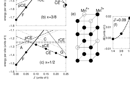
Now let us analyze our results for =1/4, 3/8, and 1/2 (Fig.1(a)-(c)), studying energies vs. for several spin patterns. The MF results agree accurately with those of the relaxation technique, confirming the reliability of the MF method. For 0.1, the FM phase is stabilized and it is insulating at =1/4, as shown in Fig. 1(d) where sharp peaks can be observed in the Fourier transform of the charge correlation function defined as =. Here is the total number of sites, = , and (=1) is the average electron number per site. The peaks in Fig. 1(d) indicate a CO pattern, schematically shown in Fig. 1(e), in which two-dimensional (2D) planes with =1 and 1/2, respectively, are stacked along the -axis.[13] This charge-ordered FM insulating phase emerging from our calculations may be experimentally detected for PCMO. Note that the “FM insulating” phase of manganites has not been analyzed in detail in previous studies, and here it is conjectured that it has charge-ordering. For =3/8 and 1/2, the FM phases are found to be metallic, since no clear peak can be observed in . This insulator-metal change in the FM state as a function of agrees quite well with PCMO experiments.
Around 0.1, a close competition occurs among the FM phases and several CE-type CO states (to be described later), indicating that a small perturbation can easily induce a first-order transition between FM and CO phases. It should be emphasized the remarkable result that such a competing region does sensitively depend on , suggesting that a CMR phenomenon can occur in a wide range of as observed in PCMO for . In fact, as shown in Fig. 1(f), the energy difference between the FM and CO phases are 0.004 at =3/8 and 0.018 at =1/2 for =0.09. If is assumed to be 0.2eV, those are about 8 and 36 Tesla, similar values as observed in the experiments.[14]
Let us discuss the detail structure of the CO phase around 0.1. Our results suggest that the possible CO phases are given by several combinations of the 2D CE-type AFM spin pattern. To simplify the discussion, the CE-type AFM configuration in Fig. 2(a) is used as the basic pattern. The possible ground states are classified into four types by the stacking manner along the -axis. (i)“the planar CE-type” (pCE), in which the pattern (a) stacks along the -axis without any change. (ii)“CE-type” (CE), in which the patterns (a) and (b) stack along the -axis alternatively. Note that this is the CE-type AFM structure observed in several half-doped manganites. (iii)“shifted CE-type” (sCE), in which patterns (a) and (c) stack along the -axis alternatively. Note that (c) is obtained by shifting (a) by one lattice spacing along the -axis. This structure, with no charge-stacking, was suggested as a possible =1/2 ground state, if the NaCl-type CO occurs due to the strong nearest-neighbor repulsion.[10] (iv)“rotated CE-type” (rCE), in which patterns (a) and (d) stack along the -axis alternatively. Note that (d) is obtained by rotating (a) by around a certain corner site in the zigzag FM chain in the - plane, or by a two lattice spacing shift. Both the rCE and sCE states have the same number of AF and FM links and their energies are -independent.
As observed in Figs.1(a)-(c), both the pCE- and rCE-phases compete with the FM phase for =1/4 and 3/8, while at =1/2, both sCE- and, especially, the CE-phase are competitive with the FM phase. As for the CO pattern, the CE-, pCE-, and rCE-phases exhibit the charge stacking due to a peak in = (Fig. 2(e)). On the other hand, the sCE-phase has the NaCl-type charge ordering with a peak at =. Since experimentally -axis charge stacking has been observed, the pCE-, rCE-, and CE-type phases are the best candidates for the ground state of the CO phases, since their energies are low in the analysis reported here.
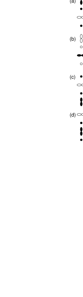
Now consider the spin correlations = . The spin patterns of the states found by combining Fig. 2(a)-(d) have the characteristic zigzag FM chains in the - plane, leading to peaks at and , where depends on the stacking arrangement. For pCE- and CE-types, is given by 0 and , respectively, due to the FM- and AFM-spin stacking along the -axis (Fig. 2(f)). For rCE-type, the peaks appear at and , since half the -axis bonds are FM and half AF. For sCE-type, four peaks exist at and with =0 and . In neutron experiments for PCMO with and 0.4,[15] a peak was found at =, suggesting that the pCE-state is the best candidate for the ground state in 0.3 0.4. The well-defined charge and spin arrangement discussed here considerably improves over previous more vague “=1/2 CE-type plus defects” descriptions of this state. At =1/2, the peak[16] indicates the CE-type as the ground state.
Note that the present results do not always provide the pCE-type as the lowest-energy state in a sizable region of at =1/4 and 3/8. To stabilize the pCE-phase it may be necessary to include the Coulomb interactions, especially the nearest-neighbor repulsion . In fact, if the nearest-neighbor charge correlation = is evaluated, for the pCE phase is found to be smaller than that of the rCE-type, indicating that rCE-type is indeed more energetically penalized by . Thus, it is reasonable to expect that a stability “window” for the pCE-state will appear if it were possible to include accurately the Coulomb interactions. Note, however, that the size of such a “window” will sensitively depend on the parameter choice, cluster size, and approximations, since a small perturbation can easily modify ground state properties in a region where several states are competing.[17] Moreover, at =1/2, the sCE-phase with the NaCl-type CO will be stabilized if is very large, making the situation more complicated since it is known that charge stacking, not present in the sCE-phase, occurs at =1/2. Nevertheless, from our present analysis it can be safely concluded that either the pCE- or rCE-states can be the lowest-energy state and play the role of the experimentally observed CO phase in the interesting region of PCMO.
As for the orbital ordering, the alternation of - and -orbitals appears in the - plane, although the exact orbital shape is slightly dependent on the stacking manner. At the corner sites in the FM zigzag path, except for sCE-phase, our calculation suggests that the orbital is polarized along the -axis and the -orbital is occupied. This result agrees well with the experimental data.[18, 19] To distinguish between pCE- and rCE-phases, the stacking of orbitals along the -axis is important. Namely, for the pCE and rCE phases, the - and -orbitals stacks in ferro and antiferro patterns, respectively. This difference can be detected for PCMO at 3/8 by using the resonant X-ray scattering technique.
Finally, the possibility of spin canting is here briefly discussed. For pCE-type at =3/8, the spins canting between two adjacent - planes along the -axis was studied as a possible way to convert continuously from pCE-type to CE-type. However, when the ground state energy is plotted against the canting angle, local minima were found only at angles corresponding to the extreme cases pCE- and CE-types, and the spin canting phase was not stabilized in the present work. However, the existence of the spin canting state cannot be totally excluded if a finite value of is considered (here = was used).
Summarizing, spin-charge-orbital ordering in manganites has been investigated at =1/4, 3/8, and 1/2 using analytical and numerical techniques. For fixed values of and , it has been found that the energy difference between the FM and CO phases is remarkably small for =1/4, 3/8, and 1/2, and a small magnetic field can induce a CO-FM transition. This result is a first step toward a possible explanation of the CMR effect in PCMO which occurs in a robust density range. Contrary to previous descriptions of these states as “=1/2 plus defects”, here it has been shown that specific charge arrangements without defects can be constructed to represent the CO states at 0. Our predictions can be verified using X ray scattering experiments.
The authors thank H. Yoshizawa for useful conversations. T.H. is supported by the Ministry of Education, Science, Sports, and Culture of Japan. E.D. is supported by grant NSF-DMR-9814350.
REFERENCES
- [1] Y. Tokura et al., J. Appl. Phys. 79, 5288 (1996); A. P. Ramirez, J. Phys.: Condens. Matter 9, 8171 (1997).
- [2] T. Hotta et al., Phys. Rev. B60, R15009 (1999).
- [3] Y. Tokura et al., J. Phys. Soc. Jpn. 63, 3931 (1994).
- [4] A. Moreo et al., Science 283, 2034 (1999).
- [5] A. Moreo et al., cond-mat/9911448.
- [6] H. Kuwahara and Y. Tokura, in Colossal Magnetoresistance, Charge Ordering, and Related Properties of Manganese Oxides, eds. C. N. R. Rao and B. Raveau, (World Scientific, Singapore, 1998).
- [7] H. Kuwahara et al., Science 270, 961 (1995).
- [8] S. Yunoki et al., cond-mat/9909254.
- [9] Y. Tomioka et al., Phys. Rev. B53, R1689 (1996).
- [10] S. Yunoki et al., Phys. Rev. Lett. 80, 845 (1998).
- [11] D. S. Dessau and Z.-X. Shen, in Colossal Magnetoresistance Oxides, ed. Y. Tokura, (Gordon & Breach, London, 1999).
- [12] If becomes too small or too large, the results will change qualitatively. For , the FM phase becomes always insulating even at =1/2, contrary to the metallic properties of this state in the CMR phenomenon. When is smaller than unity, the FM insulating phase does not appear even at =1/4, also contrary to experiments for the (Pr,Ca) based manganite. Thus, a moderate value of between 1 and 2 appears reasonable for PCMO.
- [13] Such an inhomogeneous charge ordering has been suggested in low-doping La1-x SrxMnO3. See Y. Yamada et al., Phys. Rev. Lett. 77, 904 (1996).
- [14] For between 0.15 and 0.20, the C- and CE-type AFM states are obtained for =1/4 and 3/8, respectively, but those results are spurious due to the lattice size. This point will be discussed elsewhere.
- [15] H. Yoshizawa et al., Phys. Rev. B52, R13145 (1995).
- [16] R. Kajimoto et al., Phys. Rev. B58, R11837 (1998).
- [17] In fact, the CE-type AFM state is the true long-range order at =1/2, as suggested in Ref. [16].
- [18] Z. Jirak et al., J. Magn. Magn. Mater. 53, 153 (1985).
- [19] Y. Okimoto et al., Phys. Rev. B57, R9377 (1998).