Annular Long Josephson Junctions in a Magnetic Field
Annular Long Josephson Junctions in a Magnetic Field: Engineering and Probing the Fluxon Interaction Potential
Abstract
The interaction of a Josephson fluxon with an external magnetic field-induced potential in a long Josephson junction is investigated experimentally. The thermal activation of the fluxon from a potential well is observed and experiments probing its predicted quantum properties are discussed. A method for engineering a magnetic double-well potential for a fluxon is proposed and the use of the coupled fluxon states for quantum computation is suggested.
PACS numbers: 74.50.+r, 05.45.Yv, 85.25.Cp, 03.67.Lx.
1 INTRODUCTION
Long Josephson junctions are known as the most clean systems to experimentally study basic properties of Josephson vortices, often also called fluxons.[1] The interaction of a Josephson vortex with a potential induced by an externally applied magnetic field has been discussed in literature in various contexts.[2, 3] Recently, first measurements reporting the thermally activated escape of the vortex from a magnetic field-induced potential well at have been reported.[4] Experiments probing the quantum properties of a Josephson vortex trapped in a field-engineered potential are currently in progress.
Our interest in this subject is related to a possibility of using macroscopic quantum states of Josephson vortices for quantum computation[5, 6]. We suggest that two distinct states of a fluxon trapped in a field-controlled double-well potential inside a narrow long junction can be used for designing a qubit, the basic unit of information in a quantum computer. We propose that by varying the external magnetic field and junction shape one is able to form an arbitrary-shaped potential for a fluxon in a junction; the amplitude of this potential can be varied in experiment by tuning the magnetic field.
In this paper we present our experimental results on the thermal escape of a fluxon from a potential well measured at different temperatures. We also discuss the quantum tunneling of a fluxon and some preliminary ideas on the engineering of a double-well potential for a fluxon.
1.1 A Fluxon in an External Potential
We consider a long Josephson junction of arbitrary shape and constant width . If is smaller than the Josephson penetration depth the junction can be considered as quasi-one dimensional. Its electrodynamics is described by a wave equation for the superconducting phase difference across the junction
| (1) |
In this representation the time and the space coordinates are normalized with respect to the inverse plasma frequency and the Josephson length , respectively.[1] In these units, the characteristic phase velocity of electromagnetic waves in the junction is unity and is usually called the Swihart velocity.[1] The left hand side of Eq. (1) is the sine–Gordon equation (SGE). The right hand side of Eq. (1) contains the perturbation terms. The term is the bias current normalized to the critical current, the damping term due to the quasiparticle resistance is proportional to . The term describes the interaction of the Josephson vortex with a spatial inhomogeneity region in the junction. In absence of perturbations the Josephson vortex is described by the exact soliton solution of the left hand side of Eq. (1)
| (2) |
where is the coordinate of the vortex and is its velocity.
Using perturbation theory to solve the perturbed SGE[7] (1) one can write down an equation of motion for the center-of-mass coordinate of the vortex in the non-relativistic limit
| (3) |
Because of the magnetic flux quantization, the trapped vortex behaves as a topologically stable, particle-like object of mass moving under the action of external forces. The force acting on the vortex can be expressed in terms of the potential . The bias current through the junction acts as a driving force (of the Lorentz type) on the vortex. The pinning force may have different physical origins. A pinning center for a Josephson vortex in a long junction can be realized by introducing a micro-short[8] or a micro-resistor[9] in the junction barrier. Pinning may also occur due to the interaction of the vortex with the junction leads[10] or interaction with parasitic magnetic flux trapped in the superconducting films. Alternatively, a vortex can be pinned by its magnetic dipole interaction with an external magnetic field.[2, 3] In the following, we consider the latter pinning induced by an external magnetic field, because this method allows to control the pinning potential for the vortex during the experiment.
1.2 Magnetic Field Interaction
The interaction of a Josephson vortex with an external magnetic field applied in the plane of an annular junction can be taken into account by the perturbation term[2, 11]
| (4) |
in Eq. (1), where is the normalized circumference of the Josephson junction, is the magnetic field normalized to , where is the magnetic thickness of the junction, and is a geometry dependent magnetic field coupling coefficient.[11]
Equivalently, in Eq. (3) the fluxon potential depends on the bias current and the magnetic field as given by
| (5) |
where is the vector normal to the junction and lying in the junction plane, and is the normalized field vector. In the limit of local interaction (), the magnetic field part of the potential can be expressed as , where is the magnetic moment of the vortex normal to the boundary of the junction.
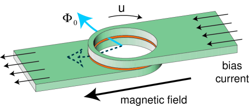
In the annular Josephson junction shown in Fig. 1, the fluxon has the lowest energy in the location where is directed along and the highest energy in the diametrically opposite location where is opposite to . The pinning potential for the vortex becomes . Subject to a driving force mediated by the bias current , the potential is tilted proportionally to , effectively lowering the potential barrier for the fluxon. Thus, the fluxon dynamics in an annular junction placed in a magnetic field is analogous to the motion of a particle in a tilted wash-board potential and can be mapped to the dynamics of the phase in a small Josephson junction.[12]
2 THERMAL ACTIVATION
At high enough temperatures, a Josephson vortex trapped in a potential well can escape from the well by a thermally activated process. The thermal activation rate can be expressed as[13, 14]
| (6) |
where is the normalized characteristic small amplitude oscillation frequency of the vortex at the bottom of the potential well. The potential barrier height in normalized units and the attempt frequency are calculated from Eq. (5). is the rest energy of the vortex, governing the energy scale of the problem.
The activation of a vortex from a potential well can be determined experimentally by measuring the switching current distribution of the Josephson junction.[12, 15] In this type of measurement, the probability of the vortex escape from a pinned state (no dc voltage drop across the junction) to a propagating state (dc voltage drop proportional to the average vortex velocity) is determined in dependence on the bias current. The experimentally observed critical current distribution is to be compared with a theoretical prediction
| (7) |
which is calculated from the bias current sweep rate and the dependence of the activation rate on the bias current . If the escape of the vortex is due to a thermally activated process, i.e. when , the critical current distribution is determined by Eq. (6).
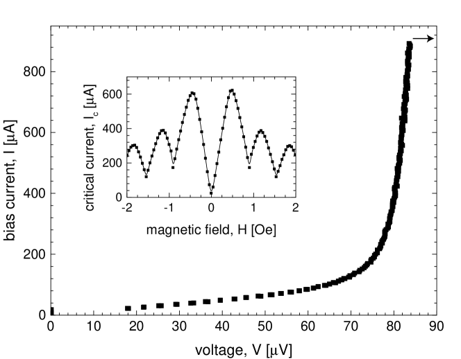
The thermally activated fluxon escape has been experimentally investigated in a number of samples. Here, we present data on an annular Josephson junction of radius and width ; its geometry is depicted in Fig. 1. The junction has a critical current density of and, consequently, a Josephson length of . A single Josephson vortex could be trapped in the junction by applying a small bias current through the junction during the transition from the normal to the superconducting state. The single-vortex state is identified by the lowest quantized resonant voltage step (saturating at a about for this particular sample) observed on the current-voltage characteristics of the junction, see Fig. 2. Also, a characteristic critical current modulation with magnetic field, accompanied by a suppression of the critical current by a factor of more than 100 at zero field, as shown in Fig. 2 and reported earlier in Ref. \onlineciteVernik97, is observed when a single vortex is trapped in the junction.
A typical measured switching current distribution at and is shown in Fig. 3. The distribution is normalized such that . By inverting Eq. (7) the activation rate can be determined from the experimental data. Using a cubic approximation of the potential Eq. (5), the expression is expected to be linear in the bias current as indeed observed in experiment, see data (open squares) in Fig. 3.
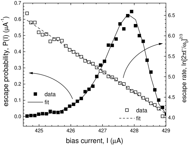
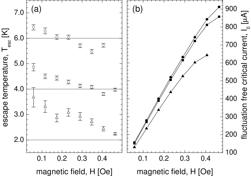
From a linear fit to , both the effective temperature of the thermal escape and the critical current in the absence of fluctuations can be determined self-consistently. The results of this analysis are shown in Figs. 4a and b for the bath temperatures and magnetic fields in the range of . The error bars in Fig. 4a indicate the uncertainty in the value of calculated using the fitting procedure explained above.
At high temperatures, the experimentally determined values of are within of the thermal bath temperatures for all values of the magnetic field. For the lowest temperature, the fitted escape temperature is notably higher than the bath temperature, which is due to the limited current resolution of approximately in the range of the measurement setup used for data acquisition in this particular experiment. Moreover, a small but systematic increase of the escape temperature for small magnetic fields is observed. This effect may be explained by considering a localized and magnetic field independent contribution to the pinning potential[4], which leads to an enhanced activation rate at low fields. In Fig. 4b, the magnetic field dependence of the fluctuation-free critical currents is plotted. The currents are observed to be larger than the critical currents measured in the patterns, as expected.
3 QUANTUM TUNNELING
In the limit of , the thermal activation of the vortex from the potential well is exponentially suppressed and eventually the temperature independent contribution due to quantum tunneling of the vortex through the potential barrier will be the dominating escape process. By measuring the switching current distribution we expect to observe a crossover from thermal activation to quantum escape at low temperatures. Experiments aiming to observe this effect are currently in preparation.
The theory of macroscopic quantum tunneling for a single Josephson vortex has been recently developed and discussed in detail in Refs. \onlineciteKato96,Shnirman97b. Essentially, the quantum tunneling of the vortex can be described in the Caldeira- Leggett approach[20], where the escape rate is given by
| (8) |
with
| (9) | |||||
| (10) |
This analysis is valid for an expansion of the potential up to third order in the vortex coordinate . Our numerical and analytical calculations of the expected switching current distributions (7) using Eqs. (6,8) show that a cross-over from thermal activation to quantum tunneling can be expected at temperatures for junctions which are several micron wide. In these calculations we took into account the effects of dissipation which can be modeled using the effective damping parameter in Eq. (10). We considered both the quasiparticle tunneling across the junction barrier and the quasiparticle impedance of the electrodes as possible origins of dissipation (also see Ref. \onlineciteKato96). At the damping parameter is typically and decreases exponentially with temperature. Therefore, this damping mechanism does not substantially decrease the cross-over temperature. In Ref. \onlineciteShnirman97b, the dissipation induced by the interaction of the vortex with plasma waves is studied, and the resulting decrease of the tunneling rate is found to be small. So far no other interaction mechanisms of the system with the environment have been taken into account.
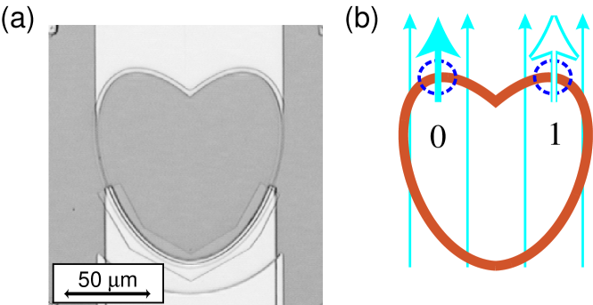
Our calculations show that the cross-over temperature can be increased close to , by reducing the junction width down to sub-micron size and optimizing the junction electrical properties. Most experiments on fluxon dynamics conducted so far have been done using long Josephson junctions of width . This limit is imposed by the standard photolithographic preparation procedure. Recently, we succeeded to fabricate high quality ultra-narrow long Josephson junctions based on niobium-aluminum-oxide trilayer technology of width down to less than .[21] In this procedure, we are using electron-beam lithography for junction definition and cross-linked PMMA for junction insulation.[21] We have successfully prepared and characterized narrow long junctions of different geometries. A photograph of a wide heart-shaped long Josephson junction is shown in Fig. 5a. First experiments on the activation of fluxons from magnetic field-induced potentials in wide annular junctions have been recently performed and will be presented elsewhere.
4 POTENTIAL ENGINEERING
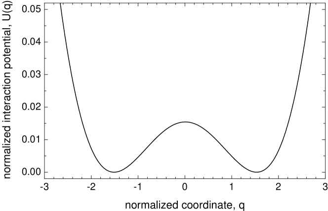
Since the interaction energy of the vortex with the external magnetic field is determined by the shape of the junction according to (5), it is possible to design an experiment with, in principle, arbitrarily shaped fluxon potential by simply varying the junction geometry. Since the major goal in our experiments with quantum fluxons will be a demonstration of macroscopic quantum coherence, one needs to realize a double-well potential for a vortex in the junction. We suggest to use a heart-shaped Josephson junction, as shown in Fig. 5a. The magnetic field applied along the symmetry axis in the junction plane forms two equal potential wells for the fluxon at locations ”0” and ”1”. At these two positions the fluxon magnetic moment is directed along , see Fig 5b. The barrier height between the wells can be conveniently controlled by the field amplitude and its angle with the symmetry axis of the junction. The corresponding potential profile at , calculated from Eq. (5) with the normalized junction length , is plotted in Fig. 6 in units of . We note that there are constraints on the potentials that can be generated by changing the junction shape, because the shape dependent part of the potential is effectively averaged over the vortex size (), as can be seen from Eq. (5). In the limit of all features of the potential disappear.
In the quantum limit, the two distinct fluxon states in the double well potential may be employed as a degenerate two-state system. Under sufficient decoupling from the environment and provided that the temperature and dissipation in the junction are low enough, the superposition of the macroscopically distinct quantum states ”0” and ”1” is expected to be observed. The preparation of the initial state for a quantum coherence measurement may be achieved by turning the magnetic field in the plane of the junction, and the final state of the vortex can be read out by performing an escape measurement from one of the potential wells.
5 CONCLUSIONS
We have considered a vortex in a long Josephson junction interacting with an externally applied magnetic field. Experiments indicating the thermal activation of the vortex from the field-induced potential have been successfully performed. Moreover, the prospects of observing quantum tunneling of a single vortex from such a potential are discussed as well as possibilities of potential engineering in order to form a double-well potential for use in a qubit.
ACKNOWLEDGEMENTS
This work was supported by the Deutsche Forschungsgemeinschaft (DFG). We would like to thank M. G. Castellano, M. Cirillo, M. Feldman, A. Kemp, Yu. Makhlin, B. A. Malomed, J. E. Mooij, P. Müller, G. Schön, K. Urlichs, and C. H. van der Wal for useful discussions.
References
- [1] A. V. Ustinov, Physica D 123, 315 (1998).
- [2] N. Grønbech-Jensen, P. Lomdahl, and M. Samuelsen, Phys. Lett. A 154, 14 (1991).
- [3] A. V. Ustinov, B. A. Malomed, and N. Thyssen, Phys. Lett. A 233, 239 (1997).
- [4] M. V. Fistul, M. G. Castellano, M. Cirillo, G. Torrioli, A. Wallraff, and A. V. Ustinov, Physica B (in print).
- [5] S. Lloyd, Science 261, 1569 (1993)
- [6] D. P. DiVincenzo, Science 270, 255 (1995)
- [7] D. W. McLaughlin and A. C. Scott, Phys. Rev. A 18, 1652 (1978).
- [8] Y. S. Galpern and A. T. Filippov, Zh. Eksp. Teor. Fiz. 86, 1527 (1984).
- [9] B. A. Malomed and A. V. Ustinov, J. Appl. Phys. 67, 3791 (1990).
- [10] D. Münter et al., Phys. Rev B 58, 14518 (1998).
- [11] N. Martucciello and R. Monaco, Phys. Rev. B 53, 3471 (1996).
- [12] J. M. Martinis, M. H. Devoret, and J. Clarke, Phys. Rev. B 35, 4682, (1987).
- [13] H. Kramers, Physica 7, 284 (1940).
- [14] P. Hänggi, P. Talkner, and M. Borkovec, Rev. Mod. Phys. 62, 251 (1990).
- [15] M. G. Castellano et al., Phys. Rev B 54, 15417 (1996).
- [16] A. Davidson et al., Phys. Rev. Lett. 55, 2059 (1985).
- [17] I. V. Vernik et al., J. Appl. Phys. 81, 1335 (1997).
- [18] T. Kato and M. Imada, J. Phys. Soc. Jpn. 65, 2963 (1996).
- [19] A. Shnirman, E. Ben-Jacob, and B. A. Malomed, Phys. Rev. B 56, 14677 (1997).
- [20] A. Caldeira and A. Leggett, Phys. Rev. Lett. 46, 211 (1981).
- [21] Yu. Koval, A. Wallraff, M. V. Fistul, N. Thyssen, H. Kohlstedt, and A. V. Ustinov, IEEE Trans. Appl. Supercond. 9, 3957 (1999).