[
Orbital Ordering in the Manganites :- Resonant X-ray Scattering Predictions at the Manganese and Edges.
Abstract
It is proposed that the observation of orbital ordering in manganite materials should be possible at the and edges of manganese using X-ray resonant scattering. If performed, dipole selection rules would make the measurements much more direct than the disputed observations at the manganese edge. They would yield specific information about the type and mechanism of the ordering not available at the edge, as well as permitting the effects of orbital ordering and Jahn-Teller ordering to be detected and distinguished from one another. Predictions are presented based on atomic multiplet calculations, indicating distinctive dependence on energy, as well as on polarization and on the azimuthal angle around the scattering vector.
pacs:
PACS numbers: 75.30.Vn, 61.10.Dp, 71.70.Ej, 71.70.ch]
I Introduction.
The manganite materials, such as La1-xSrxMnO3 and La1-xSr1+xMnO4, have received much attention recently, due to the complex interplay of electronic, spin and orbital degrees of freedom which they exhibit. This includes observation of colossal magneto-resistance and a large variety of phase transitions as a function of temperature, magnetic field and doping. Among the most interesting of late have been the charge and orbitally ordered states observed in a variety of materials such as La0.5Sr1.5MnO4[1, 2], LaMnO3[3], La0.5Ca0.5MnO3[4], (see also[5, 6]), La0.33Ca0.67MnO3[7], and La0.25Ca0.75MnO3[8]. As the temperature is lowered all of the materials (except for the undoped LaMnO3) show a charge ordering transition in which separate sublattices develop for Mn3+ and Mn4+ ions. An orbital ordering transition on the Mn3+ sublattice (all Mn sites in the case of LaMnO3) is then believed to occur, followed at (generally) lower temperatures by a magnetic ordering transition. The structure of all of these orbitally ordered states is believed to be very similar, and our results will be relevant to all. The exception will be LaMnO3, for which the period of the orbital order is too small, (see later). For simplicity we will refer mostly to the layered material, La0.5Sr1.5MnO4, returning to the others at the end.
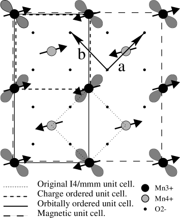
In the case of La0.5Sr1.5MnO4 the charge ordering transition is at about , with a unit variation of valence observed between the sublattices[1, 2]. This results in a doubling of the unit cell and the appearance of forbidden reflections at, for example, . At about , as seen by neutron scattering [1], a complex antiferromagnetic ordering occurs, involving both manganese sublattices. (See figure 1.) However, the antiferromagnetic transition observed in the magnetic susceptibility[9] is higher, concurrent with the charge ordering. It seems likely, therefore, that in-plane antiferromagnetic order develops at a temperature and becomes fully three dimensional at . (Rod-like neutron scattering has been reported between and [1].)
At the Mn3+ sites the Hund’s rule coupling is strong, and the crystal field has a large cubic () component. Described at one electron level, the Mn3+ configuration thus becomes a two fold degenerate configuration. (See figure 2.) This degeneracy can be lifted, with (in principle) an associated a Jahn-Teller (JT) distortion of the oxygen octahedron, reducing the symmetry to . Hence we shall denote the two components of the level as and . Goodenough[10] showed that the spin ordering is actually dependant upon the ordering of this orbital degree of freedom. Above all Mn sites have (part) filled, oriented along the crystal axis with a macroscopic tetragonal distortion. Below , however, a distinctive “herring-bone” pattern is required in order to explain the observed spin structure, as shown in figure 1. This orbital pattern again doubles the unit cell, having the wavevector . This is claimed to have been observed recently using resonant X-ray scattering at the Mn edge[2]. These results indicate that orbital order develops at the same temperature as the charge ordering:- . The fact that the spins do not order out of plane until a lower temperature is not in disagreement with this, since for La0.5Sr1.5MnO4 Goodenough’s orbitally mediated spin interactions only produce couplings in the plane, not up the axis. This leaves us with at least two possible mechanisms for the orbital ordering - it could be due to the spin ordering it permits, or to the JT distortions, or to a combination of the two. The question of which mechanism is the more important is still disputed. In other materials (such as[11] LaMnO3 and[4] La0.5Ca0.5MnO3) the ordering of the JT distortions around the Mn3+ sites has been observed directly, using high resolution neutron and X-ray diffraction, and crystallographic refinement. The level of distortions appears to vary somewhat, from about 7 to 12, suggesting that the JT mechanism may at least be not the sole mechanism of importance. Indeed, in La0.5Sr1.5MnO4 only a 1 oxygen breathing mode has so far been observed[1], although detailed crystallographic refinement is not reported. It could thus be suggested[2] that here the JT distortions actually remain along the axis even when the orbitals have ordered in the plane, and that the only mechanism of importance for this material is the Goodenough spin ordering mechanism. The complete absence of accompanying JT distortion ordering in the plane seems very unlikely, however. More detailed crystallographic refinement might be able to clarify this, as was the case[4, 12] for La0.5Ca0.5MnO3.
What is clear is that the interaction and interdependence of the spin, orbital and JT ordering is complex, and not yet fully understood. In order to approach a better understanding it would be very helpful to be able to observe the JT and orbital ordering independently of one another. The edge experiments so far performed fail to do this. They are indirect, in the sense that they probe primarily the shell, rather than the shell in which the supposedly ordered orbitals lie. The sensitivity was thought to have arisen from a mixture of the Coulomb interaction with the ordered electrons and the JT distortion of the site[15]. It has since been shown[13, 14] that the experiment is about 100 times more sensitive to the accompanying JT ordering than to the orbital ordering. Although an interference term between the two[14] does leave the possibility of distinguishing them by looking at the energy dependence of the peak, it seems rather doubtful that a direct observation of orbital ordering, as distinct from JT ordering, is possible at the Mn edge. Since the orbital believed to order is the Mn3+ , it seems logical to try resonant scattering at the Mn and edges, probing the shell itself. Unfortunately these edges lie in the soft X-ray region, so, although the Bragg angle for the reflection is real ( at the edge), the penetration depth will be very short. This will make the experiment surface sensitive and rather difficult, but not necessarily impossible. It is certainly the correct way to proceed if one wishes to directly probe the orbital order in these materials.
In the next section we will discuss the origin of the scattering and its azimuthal and polarization dependence. In section III we perform crystal field multiplet calculations to examine the energy dependence of the scattering and we discuss the distinct effects of orbital and JT ordering. Conclusions are presented in section IV.
II Polarization and Azimuthal Angle Dependence.
In contrast to the edge experiment, interpretation of the edge experiment, where a electron is promoted directly into the shell, is very clear. At one electron level, if the orbital is filled, (see figure 2,) the edge itself consists of the transition . This will clearly have a very different amplitude if the incoming photon is polarized parallel rather than perpendicular to the local “” direction () of the ion. This local direction alternates along the direction between the and axes of the crystal, with periodicity (relative to the original unit cell). For light polarized in the plane one therefore anticipates seeing the forbidden reflection, the amplitude being proportional to the difference between the scattering amplitude for a Mn3+ ion with its local direction parallel to the crystal axis and the scattering amplitude for one with its local parallel to . This is, of course, the same as the difference between the amplitudes for light polarized parallel and perpendicular to the direction of an individual ion. Light polarized parallel to the crystal axis, however, is perpendicular to the local directions of all the Mn3+ ions, so the scattering factor is the same at each site, and the scattering must be zero. This leads to a complex dependence on polarization and on the azimuthal angle around the scattering vector.
More rigorously, the scattering can be viewed as originating in the 3rd term of the single ion E1 resonant scattering amplitude given by Hannon et al.[16]
| (1) |
where are the spherical components of the transition amplitude and () the polarization vector for the incoming (outgoing) beam. The scattering amplitude at the reflection is given by the difference between for two Mn3+ ions with equal to and . (Unit vectors along and respectively.) Hence
| (4) |
The polarization dependence, being purely geometric, is the same as that previously observed at the edge[2, 3]. Resolving into and components, and performing two rotations (firstly through the azimuthal angle , secondly through around , since the wavevector is along but the orbitals alternate between and ) we can express the polarization in terms of the crystal coordinates. It is then straightforward to show that and scattering is forbidden. For the and channels the scattering intensity turns out to be
| (5) |
where is the scattering angle, and the azimuthal angle around the scattering vector.
More interesting is the energy dependence. From the naïve description above it is intuitively clear that there must be at least one energy range where , since is filled and is empty. Indeed, one expects there to be scattering in a second, higher energy, as the presence of an electron in the orbital will split the and orbitals by the Coulomb interaction. This will happen even in the absence of any JT distortion. This is because the Coulomb interaction between two electrons occupying orbitals with the same spatial distribution should be much larger than that between electrons in orbitals with different spatial distributions. If the latter Coulomb interactions are neglected, then, at one electron level, we should not expect any splitting in the level, unless it comes from Jahn-Teller effects. We therefore also anticipate some differences between the case of orbital ordering alone, and that of combined orbital and JT ordering. As discussed above, the latter case is the most likely, so we would here anticipate three main peaks at both the and edges.
These arguments tell us nothing about the relative size or spacing between the peaks, or of the possibility of smaller peaks being obscured by larger ones. So, to be more concrete, and to have a more detailed idea of the energy dependence that can be expected for , we have performed an atomic multiplet calculation for Mn3+ in a crystal field, using the Cowan multiplet codes and the “Racah” crystal field programme of B. Searle. There being no clear set of crystal field parameters in the literature we first performed a fit to the soft-XAS spectrum for LaMnO3[17]. The atomic environment of the Mn3+ ions in LaMnO3 is similar in coordination and symmetry to that in our case.
III Crystal Field Multiplet Calculations and Energy Dependence.
A Fit to the XAS Spectrum of LaMnO3.
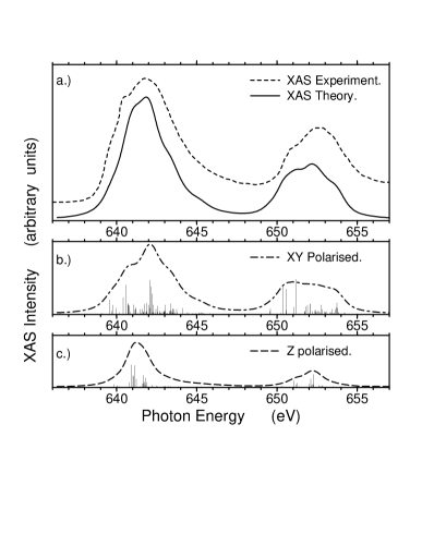
Our fit to the soft-XAS spectrum is shown in figure 3a. Hartree-Fock values for the Slater integrals are scaled to 65, and crystal fields parameters are = 3.42, = -4.05 and = -2.34, where etc are the relevant branchings for the crystal field group chain , in Racah notation. (This corresponds to , in standard notation.) The scaling of the Hartree-Fock parameters is strong, but this is in keeping with the findings of previous related studies [18, 17]. Note also that the line of parameters , , , with scaling, produces very similar results.
Using symmetry we find good agreement with the experiment, in contrast to Abbate et al.[17] who got only a rough fit using symmetry. There remain, however, a few features of the spectra that do not quite match. These should be due partly to the presence of ligand holes, (absent in our calculation) and partly to the neglect of the inequivalence between the and directions. (Each Mn3+ has one of these in the crystal’s plane, the other along the axis.) This would reduce to , with an additional splitting between and , and alterations to others.
It is also the case that there is an anisotropy at the Mn4+ sites, since each Mn4+ has two filled Mn3+ orbitals pointing towards it, set apart, and two empty. (See figure 1.) This breaks the inversion symmetry and is modulated with the same wavevector as the orbital ordering itself. However, the Mn3+ lie the other side of the intervening oxygen sites, so the effect should be tiny compared to that on the Mn3+ sites. It should also occur at a slightly different energy. We are therefore confident that any effect seen in this experiment would be arising from the orderings on the Mn3+ sublattice itself.
In figures 3b and c we include the XAS contributions from X-rays polarized in the plane and along the -axis. Although the one-electron picture is blurred out by the multiplet interactions it is still possible to discern about 4 broad levels, most clearly at the edge. The 1st and 4th are polarized mostly in the plane, the 2nd largely parallel to the -axis, but with significant contributions also. The 3rd is again mixed, but predominantly . The first band can be reasonably identified as the level, albeit rather broadened and with other contributions mixed in. The others can probably be labelled, at one electron level, according to the scheme in figure 2, provided the and are sufficiently broadened and shifted that they overlap completely. Hence, the 2nd level comprises mostly the and of the split level, and the 3rd the component, overlapping with the from the . Finally, the 4th level would be from transitions to the orbital.
B Resonant X-Ray Scattering.
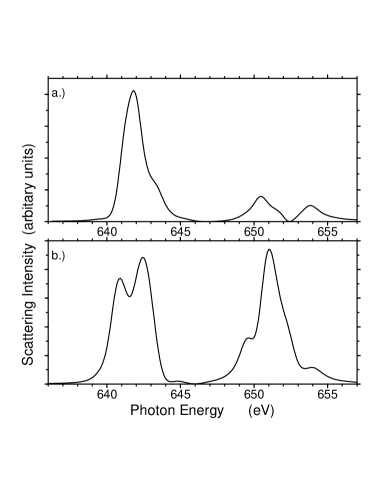
Turning to the resonant scattering, we plot in figure 4a the maximum scattering intensity, . We see that there is a distinct structure as a function of energy. Comparing the energy scale with that of figure 3 we note also that the greatest intensity does not come from transitions to the empty orbital itself, but, from transitions to the split levels, just above. This strong scattering peak occurs only at the edge. On its high energy side we see a shoulder, but any shoulder to the low energy side is too small to be noticeable. At the edge we see two main peaks, with a shoulder on the high energy side of the lower one. The nature of these other peaks and shoulders will be discussed later.
The energy dependence of carries specific information about the environment of the Mn3+ sites, helping us answer questions to do with the type and origin of the ordering, as discussed previously. For example, in the edge experiments it was not possible[2] to differentiate between the / orbital ordering actually believed to occur and the alternative / ordering. However, at the edges the two should have very different energy dependences. To illustrate this point, we have recalculated the edge scattering, keeping the same crystal field magnitudes as before, but reversing the sign of the terms and . This makes the occupied orbital, mimicking the alternative / ordering. The result is shown in figure 4b, and is clearly distinguishable from 4a. We emphasize, however, that this curve is not intended as a specific prediction, since it is not derived from any experimental spectra for a Mn3+ ion with the orbital filled. It is intended just as an illustration that much more information should be available at the edges than at the edge. Extraction of such information would require detailed fits to actual experimental data, when such exist.
C Distinguishing Orbital Order and Jahn-Teller Order.
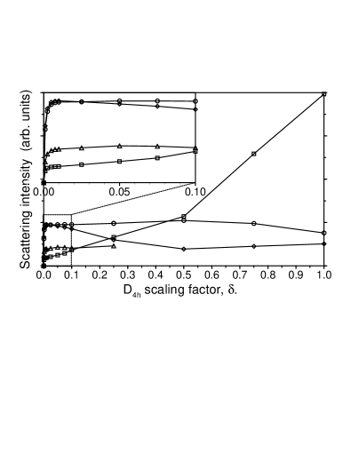
It should also be possible to differentiate between the scattering due to orbital ordering alone and that due to combined orbital and JT distortion ordering, helping us tackle the question of which mechanism is the more important. Within the confines of the multiplet codes we need to keep and non-zero in order to make the occupied orbital. This means that so far we have actually included the JT effects as well, implicitly assuming the involvement of that mechanism. We would now like to identify which parts of the predicted spectrum, if any, come from the JT ordering, and which come from orbital ordering alone. To do this, we note first that whilst and must remain non-zero, in order to split and and observe orbital ordering at all, the actual size of the splitting required is not important, down to some limit set by truncation within the code. Thus we can choose a very small tetragonal distortion in order to select the orbital in the initial state, and then use scaling arguments to differentiate between the orbital ordering effects and the residual JT effects. Hence we can scale and by some , progressively removing the effects of the JT distortions, whilst keeping the scattering from the ordered orbitals. (Note that is not intended as an experimental fitting parameter, it is simply a tool to “switch off” the JT distortion, leaving pure orbital ordering, so that we can separate out the two contributions.)
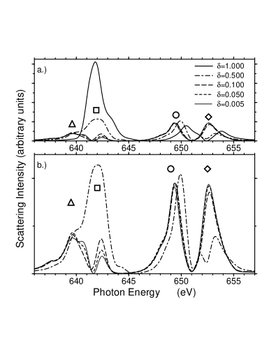
In figure 5 we show the scattering for a few values of . (The ratio is kept constant.) For the JT effects are small and we are essentially left with the effect of the orbital ordering alone. In figure 6 we plot the heights of the four main peaks against . It is clear that there is only one significant peak due directly to the JT distortion. It is labelled with a square symbol on figure 5, and lies in the edge. This is the peak corresponding earlier to transitions into the split levels. In figure 6 the peak height scales to a very small value as , indicating an OO contribution of only about 4%. A better estimate might have come from scaling the weight under the peak, but this is complicated by the presence of the shoulder. Comparing the weight under this peak in the and curves, an OO contribution of around 1.3-1.7% is obtained, depending on where one cuts the shoulder. That this peak should be due essentially to the JT distortions rather than the presence of the ordered electron is in complete agreement with our previous one electron level arguments. The equivalent peak at the edge is the shoulder on the lower main peak. The dependence of its energy is different from that of the two main peaks at this edge, however, so it is visible as a separate peak in the curve. At smaller it is too small to be distinguishable. The difference between this peak and the equivalent peak at the edges is due to the core hole potential; this we have verified by repeating the calculation with the core hole potential absent.
The three other peaks are due principally to the ordered orbital occupancy, as their heights do not diminish with diminishing . Indeed, the heights are stable over about two orders of magnitude, and scale to non-zero values as the JT distortions go to zero. (Their collapse to zero for very small is an artifact of numerical truncation in the calculation.) The most interesting of these is the peak labelled with a circle at the edge. Comparison with the peak identifications in figure 3 (see previous section) shows that this is due to resonant transitions into the unoccupied , so we would expect to see it even in the complete absence of JT distortions. Estimating the size of the JT contribution from the scaling of the peak height is difficult, but suggests a negative contribution of around 8-20%. It is equally difficult to use scaling of the weight under the curve, as there is again a shoulder. Depending on where we cut the shoulder we get estimates in the 10-30% range. It can also be seen clearly that the location of the peak shifts downwards in energy by 1.06eV. The equivalent peak at the edge moves even further, being invisible for , hidden under the square labelled peak. At first glance this movement might suggest that the contributions from JT ordering are much larger, but this is not the case. At one electron level (see figure 2) we see that, even in the absence of any JT distortion, this peak should exist as soon as the orbital is occupied and ordered. Any JT distortion on top of this will not add or take anything at all from the scattering intensity, but it will move the level upwards in energy, and hence also the scattering. This is indeed what we see in figure 5. The changes in peak height and weight come only when multiplet contributions beyond one electron level are included. Hence, the location of this peak in energy is controlled partly by OO and partly by JT ordering, but its existence and weight are still essentially due to the OO itself.
The other two peaks arise from the splitting of the levels. At the edge this peak (labelled with a diamond) moves downwards as the JT distortions are switched off, and actually grows. The equivalent peak at the edge is not labelled, as it is weaker, and moves from being a shoulder on the square labelled peak at to being a shoulder on the triangle labelled peak at and below. The diamond labelled peak actually grows by almost a factor of two as the JT distortions are removed. This is again understandable at one electron level. As we noted earlier, in the absence of any distortion, we would expect the orbital to lie above the orbital due Coulomb interaction with the occupied . However, in the absence of the Coulomb interaction, but with the JT distortion elongating the ion along the axis, we would expect to lie below . Hence for the diamond labelled peak the two contributions are in competition. Apparently the JT dominates at , since figure 3 indicates that lies below . In figure 6 we see a minimum in the peak height around , where the two contributions balance, (multiplet broadening prevents the peak disappearing completely.) Below this OO dominates, and the peak intensity grows.
The prediction from the scaling is that the scattering shown in figure 4a is dominated at the edge by JT ordering, although orbital order leads to a clear shoulder to the high energy side of the main JT peak. At the edge, on the other hand, whilst the scattering is predicted to be rather weaker, it is dominated heavily at the lower end by the orbital ordering. Observation of scattering intensity here would thus be a reasonably good measurement of orbital order, independent of the presence or absence of JT order. Confirmation of this could again be sought by more detailed fitting to experimental data, were the measurement to be actually performed. (We anticipate some difference between experimental data and that shown in figure 4a since our calculation in based upon a fit to the XAS spectrum for Mn3+ in a slightly different setting.)
D Orbital Ordering in Other Materials.
Returning now to the other manganite materials, we note that, for example, La0.5Ca0.5MnO3 shows exactly the same charge and orbital ordering in the plane[4], leading to the same energy, polarization and azimuthal dependence as for the layered material. The unit cell is normally indexed differently, so that the fundamental wavevector is , but this again gives a period of about 10.9Å, or an angle of 62.9∘ at the Mn edge. Similarly for La0.33Ca0.67MnO3, orbital order has been reported [7] with a wavevector of , giving a period around 16.2Å. The structure is slightly different, but the Mn3+ local directions alternate between and , still giving the same energy, polarization and azimuthal dependence. In practise, we expect that this technique, if realised, could measure and differentiate between both JT and orbital ordering in a wide variety of manganite materials. The exception, unfortunately, is LaMnO3 itself. Here, in the absence of Mn4+ ions, the period of the orbital order is only about 5.4Å, too short for the Mn edges. The minimum orbital order period for which a reflection could exist at the Mn edge is about 9.7Å.
IV Conclusion.
We have demonstrated that, in principle, it should be possible to make direct observations of orbital ordering as well as Jahn-Teller ordering in many of the manganite materials, using resonant X-ray scattering at the Mn edges. This is likely to be true also of resonant edge scattering in other materials which combine orbital ordering with charge ordering. For the current case of the manganites, we have shown that sensitivity at the edge should be primarily to the accompanying Jahn-Teller ordering, whilst that at the edge should be due to the orbital ordering itself. The intensity would have specific energy and polarization dependences, and a dependence on the azimuthal angle around the scattering vector. The measurement would be theoretically much more direct than the disputed resonant X-ray scattering measurements so far performed at the Mn edge, because dipole selection rules allow scattering directly from the ordered orbitals themselves, rather than from some other unoccupied orbitals, strongly hybridised with surrounding oxygen orbitals, higher up in energy. With the aid of suitable fitting of the energy dependence, the measurement would provide much more detailed information, particularly about the type of ordering present, the orbitals actually involved and the relative importance of the possible ordering mechanisms.
Acknowledgements.
CWMC would like to thank P. Carra for helpful discussions and assistance in learning to use the Cowan and Racah codes. He also thanks E. Pellegrin, T. Forgan, F. de Bergevin and P. Abbamonte for helpful discussions.REFERENCES
- [1] B.J. Sternleib, J.P. Hill, U.C. Wildgruber, G.M. Luke, B. Nachumi, Y. Moritomo, Y. Tokura, Phys.Rev.Lett. 76, 2169 (1996)
- [2] Y. Murakami, H. Kawada, H. Kawata, M. Tanaka, T. Arima, Y. Moritomo, Y. Tokura, Phys.Rev.Lett. 80, 1932 (1998).
- [3] Y. Murakami, J.P. Hill, D. Gibbs, M. Blume, I. Koyama, M. Tanaka, H. Kawata, T. Arima, Y. Tokura, K. Hirota, Y. Endoh, Phys.Rev.Lett. 81, 582 (1998)
- [4] P.G. Radaelli, D.E. Cox, M. Marezio, S-W. Cheong, Phys.Rev.B. 55, 3015 (1997)
- [5] T. Vogt, A.K. Cheetham, R. Mahendiran, A.K. Raychaudhuri, R. Mahesh, C.N.R. Rao, Phys.Rev.B. 54, 15303 (1996) .
- [6] M. von Zimmermann, J.P. Hill, M. Blume, D. Casa, B.Keimer, Y. Murakami, Y. Tomioka, Y. Tokura, cond-mat/9905285.
- [7] C.H. Chen, S-W. Cheong, H.Y. Hwang, J.Appl.Phys. 81, 4326 (1997).
- [8] S.W. Cheong, H. Y. Hwang, in Colossal Magnetoresistance Oxides, ed. Y. Tokura, (Gordon & Breach 1999).
- [9] F. Damay, C. Martin, A. Maignan, B. Raveau, J.Mag.Mag.Mat. 183, 143 (1998).
- [10] J.B. Goodenough, Phys.Rev. 100, 564 (1955).
- [11] J. Rodríguez-Carvajal, M. Hennion, F. Moussa, A.H. Moudden, L. Pinsard, A. Revcolevschi Phys.Rev.B. 57, R3189 (1998)
- [12] P.G. Radaelli, D.E. Cox, M. Marezio, S-W. Cheong, P.E. Schiffer, A.P. Ramirez Phys.Rev.Lett. 75, 4488 (1995)
- [13] I.S. Elfimov, V.I. Anisimov, G.A. Sawatzky, Phys.Rev.Lett. 82, 4264 (1999).
- [14] M. Benfatto, Y. Joly, C.R. Natoli, Phys.Rev.Lett. 83, 636 (1999).
- [15] S. Ishihara, S. Maekawa, Phys.Rev.Let. 80, 3799 (1998).
- [16] J.P. Hannon, G.T. Trammel, M. Blume, D. Gibbs, Phys.Rev.Lett. 61,1245 (1988).
- [17] M. Abbate, F.M.F. de Groot, J.C. Fuggle, A. Fujimori, O. Strebel, F. Lopez, M. Domke, G. Kaindl, G.A. Sawatsky, M. Takano, Y. Takeda, H. Eisaki, S. Uchida, Phys.Rev.B. 46, 4511 (1992)
- [18] E. Pellegrin, et al. 60 reduction of Slater integrals quoted in a private communication. (1998)