Mesoscopic Analysis of Structure and Strength of Dislocation Junctions in FCC Metals
Abstract
We develop a finite element based dislocation dynamics model to simulate the structure and strength of dislocation junctions in FCC crystals. The model is based on anisotropic elasticity theory supplemented by the explicit inclusion of the separation of perfect dislocations into partial dislocations bounding a stacking fault. We demonstrate that the model reproduces in precise detail the structure of the Lomer-Cottrell lock already obtained from atomistic simulations. In light of this success, we also examine the strength of junctions culminating in a stress-strength diagram which is the locus of points in stress space corresponding to dissolution of the junction.
pacs:
61.72.Lk, 62.20.FeIn FCC metals, a key mechanism limiting the movement of the dislocations is the “forest intersection” mechanism, where segments of dislocations on a glide plane are rendered immobile as a result of intersection with dislocations on other glide planes. Such intersections can lead to complex dislocation junction structures since the cores of the dislocations in these metals are dissociated into partial dislocations separated by a stacking fault[1]. Furthermore, the structure of the junction also depends strongly on the geometric disposition (such as the line directions and Burgers vector) of the participating dislocations. A core level analysis of all the possible junction configurations is therefore important from a number of perspectives. Such core level calculations in conjunction with statistical averaging procedures can provide key parameters that are used in models that predict the mechanical behavior of metallic crystals on a macro-scale. These models include single crystal plasticity models[2] and the computational models that simulate the dynamics of a large collection of dislocations[3]. In this letter we develop a mesoscopic dislocation dynamics model that can be used to simulate the structures and strength of dislocation junctions in FCC metals and may obviate the need for direct atomistic simulations of these junctions.
For simple dislocation intersection geometries, the structure of dislocation junctions has been studied extensively in a series of classic papers by Hirth and coworkers[4] using the theory of linear elasticity. Analytical insights into more complicated intersection geometries have been gained by using the line tension approximation for the dislocation lines[5]. While this approach provides a great deal of physical insight into the junction structure and strength, it ignores the extended core structure of the dislocations as well as the long range interaction between the dislocation segments. With rapid advances in computational power in recent years, it has become possible to perform atomistic simulations of dislocation intersections[6, 7, 8]. Typically these simulations[7, 8], performed using cells of the dimensions of 300-400 containing over a million atoms, are computationally very demanding and raise serious questions concerning the role that boundary conditions play in dictating the results.
In the present study, we develop a mesoscopic method to study the structure and strength of dislocation junctions that includes the dissociation of the dislocation core into partial dislocations. The interaction between the dislocations are treated using the theory of anisotropic elasticity[9]. We find that the our method reproduces, in precise detail, all the features of the dislocation junction structure obtained from a full atomistic treatment of the dislocation core. Our results demonstrate that the junction structure is almost entirely determined by elastic interaction between the partial dislocations and the stacking fault energy. Furthermore, the adaptive procedures that we use allow us to simulate dislocation junctions that have lengths of the order of microns. An atomistic simulation of these large junctions would require simulations involving an excess of a billion atoms. In order to clearly demonstrate the role of the stacking fault in determining the junction structure, we will consider dislocation junctions in two metals, namely, Al, with a high stacking fault energy (0.104 ) and Ag, with a low stacking fault energy(0.016 )[10]. We limit our discussions to the Lomer-Cottrell lock[1]; a complete investigation of other junctions will be reported elsewhere.
The simulations are carried out through an adaptive finite element based dislocation dynamics algorithm that is described in detail in Ref.[11]. We start our simulations with straight dislocation lines that are pinned at their end points. Simulations are carried out until the dislocations glide to their equilibrium configuration. Each dislocation line is allowed to split into partial dislocations by accounting for the energy cost of the stacking fault created in the process. In the starting configuration, the partial dislocations are discretised into straight segments of equal length. A time step of the dynamics process consists of moving the node connecting the segments with a velocity that is proportional to the nodal driving force. The computation of the nodal force requires the knowledge of the force per unit length at certain quadrature points on the dislocation segments that are attached to the node. The force per unit length at any point on a segment consists of a component arising from the stresses due to all the dislocation segments in the system including the segment itself. The Brown regularization procedure is adopted to guarantee that the self-stress contribution is well behaved[12]. When the interaction between the segments belonging to different dislocations is attractive, they approach each other in the process of forming a junction. The stress acting on one of the segments due to the other one diverges as their separation vanishes. In our calculations, the stresses are constant for distances less than a critical separation distance, , by the value of stress computed at . As a result, the segments are locked once they are closer than this critical distance; a junction has formed. From an elastic perspective, at distances larger than , the stresses produced by the junction segments correspond to those produced by a dislocation whose Burgers vector is the sum of the Burgers vectors of the two segments that make up the junction. Once the junction is formed, it can unzip if the external stresses cause the segments that form the junction to move away from each other. The calculations described here were carried out with , although we have also considered the cases in which the cutoff was and , without noticeable change to the resulting junction structures. In addition to the stress from the dislocation segments, the force per unit length consists of a component arising from the stacking fault. This component is normal to the dislocation segment and has a magnitude that equals the stacking fault energy and acts in a direction tending to shrink the stacking fault. In the simulations that we describe, we have ignored the frictional stress since we have found that its inclusion is unimportant. A key feature of our simulations is the adaptive positioning of the nodes. As the simulation progress, the nodes are redistributed, so that the regions with large curvature have more nodes per unit length.
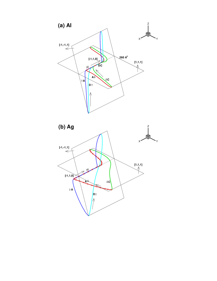
We demonstrate our results by first considering the equilibrium configuration of a Lomer-Cottrell lock as shown in Fig. 1. This configuration has been chosen so as to make a direct comparison of our results with the atomistic simulations for Al reported in Ref.[8]. The pinning points are arranged such that in the starting configuration the dislocation line directions make an angle of with the direction. This direction coincides with the line of intersection of the slip planes of the dislocations that form the junction. The initial separation between the dislocations was chosen to be 6. The line directions of each of the partial dislocations and their slip plane normals are given in the figure. We follow the notation described in Ref.[1] to label the Burgers vectors of the partial dislocations by referring to the Thompson tetrahedron. For example, the dislocation splits into partial dislocations and with Burgers vectors and respectively. As is evident from the figure, the junction segment in the case of Al, has split into separate parts. A stair-rod segment with Burgers vector of the type forms an extended node on the left side of the junction. The remaining part of the junction is a sessile Lomer dislocation segment. The length of the stair-rod segment is 38, while the Lomer is 42, which is in excellent agreement with the atomistic results[8]. The dislocation dynamics model also agrees with the atomistic results in predicting the structure of the right hand node, which is point-like and is the meeting point of constricted dislocation segments.
As an extension of earlier results and to highlight the dependence of the junction structure on the stacking fault energy, we have also computed the geometry of the Lomer-Cottrell junction in Ag. The dislocation junction in Ag, for this configuration, has an entirely different structure. The junction segment is entirely composed of a stair-rod dislocation of length Å. The smaller stacking fault energy keeps the segments and from participating in the junction formation process. Before proceeding to discuss the effect on junction structure of the length and the orientation of the participating dislocations, we pause to illustrate the adaptive nodal repositioning process used in the simulations. It can be seen from Fig.1b that the nodes on the red dislocation line have evolved from a case where they are spaced at equal intervals to a case where there are more nodes in the regions with large curvature.
In order to consider the effect of varying the distance between pinning points and the orientation of the dislocations on the junction structure, we consider the highly symmetric geometry shown in Fig. 1, where the participating dislocations have the same orientation and identical distances between the pinning points. In the case of the dislocation junction in Al, we find that the length of the Lomer segment increases with increasing distance between the pinning points, while the length of the stair-rod segment is not altered. By way of contrast for the junction in Ag, the length of the stair-rod keeps increasing on increasing the distance between the pinning points up to about 1000. Beyond this length, the Lomer segment appears and increases in length, while the left hand stair-rod node attains a constant length of about 600. We therefore conclude that the length of the extended node is determined largely by the stacking fault energy of the crystal. This calculation also illustrates the ability of our method to handle large junction lengths which are clearly beyond the reach of the atomistic simulations.
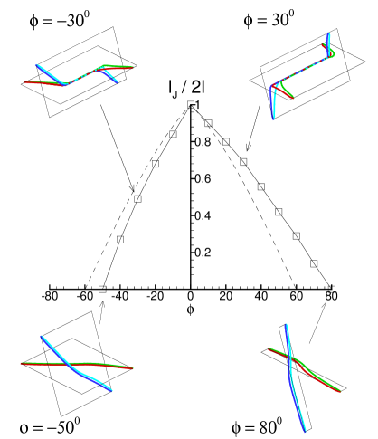
We now consider the effect of altering the junction angle on the structure of the dislocation junction. We use to denote the angle between the dislocation line direction in the starting configuration and the direction, to represent the junction length and for the distance between the pinning points. In Fig. 2, we plot the junction length and structure as the orientation of the pinning points is altered. The dislocation junction ceases to form at angles smaller than -500 or angles greater than 800. For comparison the we also show the results of the line tension model tension model of Saada[5]. Within this model the junction length vanishes for angles that are larger than 600 or smaller than -600. The difference can be understood by noting the difference in the node structures in junctions with negative angles in Fig. 2. The left node for the -300 configuration is made up of a stair-rod of the type , while the right node is made up of a new stair-rod segment , which is a type dislocation. The existence of the in the negative angle junctions is counterintuitive, since a simple line tension estimate[1] shows that this type of stair rod has 4 times higher energy per unit length than the stair-rod. The dislocation interactions that are ignored in this simple line tension argument conspire to make this stair-rod segment stable. The asymmetry in the junction formation angles can be attributed to this difference in junction structures of the positive and negative angle junctions.
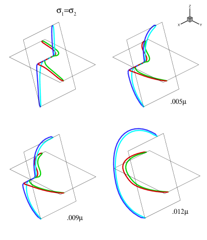
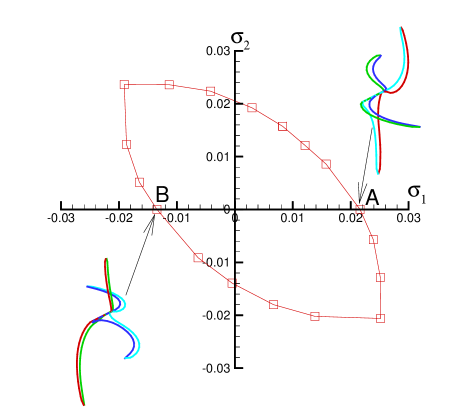
Far more interesting than the structure of junctions is their behavior under stress. Line tension models predict that the arms of the dislocations bow out under the influence of the external stress, while the junction translates along the line of intersection of the slip planes. As the junction translates, its length decreases as a result of the applied stress via an “unzipping” mechanism. Fig. 3 shows the evolution of the dislocation junction in Fig.1a under the influence of an externally applied stress. The resolved shear stress on the dislocations in the and slip planes are labeled and respectively. We have chosen the orientation of the applied stress for this series of pictures such that . On increasing the stress, the length of the Lomer segment initially increases on going from no applied stress to a stress of 0.006 ( is the shear modulus). This is consistent with the atomistic simulations, but is at variance with the line tension models, which always predict a decreasing junction length with increasing stress. On increasing the stress further, the junction translates and undergoes an unzipping mechanism, whereby the length of the Lomer segment decreases. This behavior is evident for the stress level of .009. On increasing the stress further, the junction breaks at a stress level of about 0.012 after which they continue to bow out. The configuration shown at stress of 0.012, is not in equilibrium, but a snap shot after the junction has been destroyed. We have carried out similar calculations for several values of resolved shear stress acting on the two dislocations. A “yield surface” for dislocation destruction is shown in Fig. 4. This surface is symmetric about the line , but depends on the sign of and . This symmetry breaking is readily understood by looking at the configurations of the dislocations under action of positive and negative (denoted in Fig. 4 by points A and B respectively) with . The presence of the stair-rod node makes it more difficult for the horizontal segment to bow out in case (A) compared to case (B) and requires a larger value of shear stress to break the junction.
It is interesting to compare the predictions of the line tension model and the atomistic simulations with the results obtained from our simulations. An important prediction of the line tension model is the scaling of the breaking stress of symmetric junctions with the distance between the pinning points, written as . The line tension model predicts the average critical resolved shear stress to break the symmetric junctions to be . We have simulated the breaking of symmetric junctions with lengths ranging from 300 to 1 by applying the external stress in different orientations. We have found that the critical breaking stress scales as . For the cases and the critical resolved shear stress behaves like and , respectively. For the junction, for the case when , the atomistic simulations gave , which is in good agreement with our results. In the atomistic simulations, performing the scaling analysis is very computationally demanding and perhaps not even realizable. The scaling of the breaking stress in un-symmetric junctions with different arm length of the participating dislocations was found to be more complicated and will not be discussed here.
Before presenting our concluding remarks, we point out the features that are missed in our model and the effect they may have on the results discussed thus far. In our simulations, the dislocations do not acquire a jog as they go past each other. While this does not affect the junction structure, it will alter the breaking stress, since the external stress should supply the energy required to create the jog. However, the jog contribution to the breaking stress is only a small fraction of the stress required to unzip the junctions[5]. In order to examine the effect of the stress cut-off distance, , we have also carried out all the above simulations by choosing to equal and . The junction structure showed very little difference in the two calculations. Also, the breaking stress in all the cases was within 10 of the values reported here.
In conclusion, we have developed an efficient method to study dislocation interactions in FCC metals. We have illustrated that the method can provide “rules” like critical angle for junction formation and breaking stress criteria, which can be used in 3D dislocation dynamics models. The results from our simulations for junctions in different configurations, when appropriately averaged, can provide parameters related to junction strength in models for single crystal plasticity. Fits to these parameters from tension tests on single crystals have revealed a hierarchy of junction strengths in FCC crystals[13]. Work is in progress to verify the observed hierarchy on the basis of our simulations. In the future we also hope to study other problems like the strength of dislocation junctions in alloys and interactions of extended dislocations with defects.
We are grateful to M. Fivel, A. Needleman, M. Ortiz and D. Rodney for illuminating discussions. We also appreciate the support of the Caltech ASCI program and the Brown University MRSEC.
REFERENCES
- [1] see, for example, J. P. Hirth and J. Lothe, Theory of Dislocations (Kreiger, Malabar, Florida, 1992).
- [2] J. L. Bassani, Adv. Appl. Mech. 30, 191(1994) and references therein.
- [3] M. Verdier, M. Fivel and I. Groma, Mod. Sim. Mat. Sc. Eng 6 755(1998) and references therein.
- [4] J. P. Hirth, J. Appl. Phys. 32, 700(1961); J. P. Hirth,ibid. 33 2286(1962); T. Jossang, J. P. Hirth and C. S. Hartley, ibid. 36 2400(1965).
- [5] G. Saada, Acta. Metall. 8, 841(1960).
- [6] V. Bulatov, F. Abraham, L. Kubin, B. Devincre and S. Yip, Nature 391, 669 (1998).
- [7] S. J. Zhou, D. L. .Preston, P. S. Lomdahl and D. M. Beazley, Science 279, 1525(1998).
- [8] D. Rodney and R. Phillips, Phys. Rev. Lett. 82, 1704(1999).
- [9] The stresses due to dislocation segments are computed using the formalism for dislocations in anisotropic solids described in Sec. 4.2 of D. J. Bacon, D. M .Barnett and R. O. Scattergood, Prog. Mat. Sc. 23, 51(1979).
- [10] The stacking fault energy of Al is obtained from the many-body potentials used in Ref.[8], while for Ag it is taken from Appendix 2 of Ref.[1].
- [11] R. V. Kukta, PhD Thesis (Brown University, 1998).
- [12] K. W. Schwarz, J. Appl. Phys. 85, 108(1999).
- [13] See, for example, P. Franciosi and A. Zaoui, Acta. Metall. 30, 1627(1982).