Electron Standing Wave Formation in Atomic Wires
Abstract
Using the Landauer formulation of transport theory and tight binding models of the electronic structure, we study electron transport through atomic wires that form 1D constrictions between pairs of metallic nano-contacts. Our results are interpreted in terms of electron standing waves formed in the atomic wires due to interference of electron waves reflected at the ends of the atomic constrictions. We explore the influence of the chemistry of the atomic wire-metal contact interfaces on these standing waves and the associated transport resonances by considering two types of atomic wires: gold wires attached to gold contacts and carbon wires attached to gold contacts. We find that the conductance of the gold wires is roughly for the wire lengths studied, in agreement with experiments. By contrast, for the carbon wires the conductance is found to oscillate strongly as the number of atoms in the wire varies, the odd numbered chains being more conductive than the even numbered ones, in agreement with previous theoretical work that was based on a different model of the carbon wire and metal contacts.
pacs:
PACS: 73.40.-c, 73.61.Ph, 73.23.-bI Introduction
The ability to manipulate matter on the atomic scale has improved greatly over the past decade. The STM has facilitated much of this progress with its ability to positionally control atoms on surfaces.[1, 2, 3, 4, 5] Experiments are now able now to move beyond the manipulation stage and measure the electronic properties of these atomic scale systems. One system of particular interest is an atomic chain. When an atomic chain is used to bridge two contacts an atomic wire is formed. Recent STM experiments have managed to measure the tunneling current through atomic wires, which have been made by positioning several atoms to form a chain between the STM tip and the substrate.[6, 7] More recently, mechanically controlled break junctions have been used to form a gold chain between two gold contacts. The conductance of these gold atomic wires was measured for different chain lengths.[8] It may also be possible to form carbon atomic wires by stretching a single walled nanotube.[9] Current work is focusing on connecting carbon wires between two metalized AFM tips.[10] Early theoretical work on atomic wires studied the electron transmission through molecular chains with a single orbital per site with nearest neighbour hopping.[11] Recent theoretical studies of these atomic wire systems based on a density functional approach have also revealed interesting phenomena, one of them being the oscillation of conductance versus the length of a carbon wire.[12]
The atomic wire is interesting from a transport point of view because it confines electrons to propagate only in one dimension. It is also on a length scale that is of the order of the wavelength of the electrons which are incident from the contacts. This means that the quantum mechanical wave nature of the electrons will be important. When waves are confined to propagate in a 1D constriction standing waves are formed. These arise because of back reflections at the boundaries between the contacts and the constriction. Electrons propagating in semiconductor waveguides have been predicted to form standing waves along the conduction channel.[13, 15] Experimentally observing standing wave formation in these systems has been difficult because these structures are formed electro-statically, which results in 1D channels that are smoothly tapered at their ends minimizing reflections there.[14, 15] We show that electron standing waves should form in atomic wires and investigate the role of the chemistry of the wire-contact interface (which has no analog in the semiconductor devices) on their behavior. Although these standing waves have not been studied experimentally at the present time, atomic wire systems may prove to be better candidates for their observation since the interfaces between a 1D wire and the contacts cannot be smooth on the atomic scale so that reflections at these interfaces should be significant.
We study electron transport through an atomic wire by calculating the wavefunction for an electron propagating along the wire. This is done using a tight binding formalism that treats both the chain and metallic leads atomistically.[16] The present work is complementary to other theoretical treatments that have been based on tight binding models of the atomic wire[11, 17, 18] or have considered jellium contacts with the wire modelled using pseudo-potentials.[12] We apply our technique to two different atomic wire systems. The first system is a homogeneous atomic wire which is made using a gold chain that bridges two gold contacts. We find that our results are consistent with the interpretation that standing waves are formed along the gold wire. The standing wave patterns that are formed are confined within the 1D channel that has the length of the gold chain. The number of standing wave resonances that occurs increases with the length of the chain. However, the conductance of gold chains consisting of different numbers of atoms is found to vary only slightly as the number of atoms changes and remains near unity as has been reported experimentally.[8]
The second system we consider is a heterogeneous atomic wire. It is a carbon atom chain attached to two gold contacts. Again our results are consistent with a description involving the formation of standing waves along the carbon chain. However, in this case the standing wave patterns formed extend significantly beyond the ends of the chain into the gold contacts. Thus in this heterogeneous system the chain is effectively lengthened due to the chemistry between the chain and the contacts. This gives rise to a greater number of standing wave resonances. The conductance is also found to oscillate with the length of the chain which is in agreement with what was found in other work.[12] The standing wave model that we describe provides an intuitive physical explanation of this predicted oscillation.
In Sec. I we present the theoretical approach used to calculate the conductance together with a description of standing wave formation in an atomic wire. We then present our calculations for gold atomic wires, a homogeneous system, in Sec. II. In Sec. III we present calculations for carbon atomic wires.
II Electron Transport in Atomic Wires: Normal Modes
An atomic wire is composed of a chain of atoms that forms a 1D constriction between two metallic contacts which act as the source and the drain. Electrons incident as Bloch waves from the source contact scatter through the 1D constriction and enter the drain. Landauer theory relates the conductance of the atomic wire to the multi-channel transmission probability for an electron at the Fermi level of the source to scatter from source to drain via .[19]
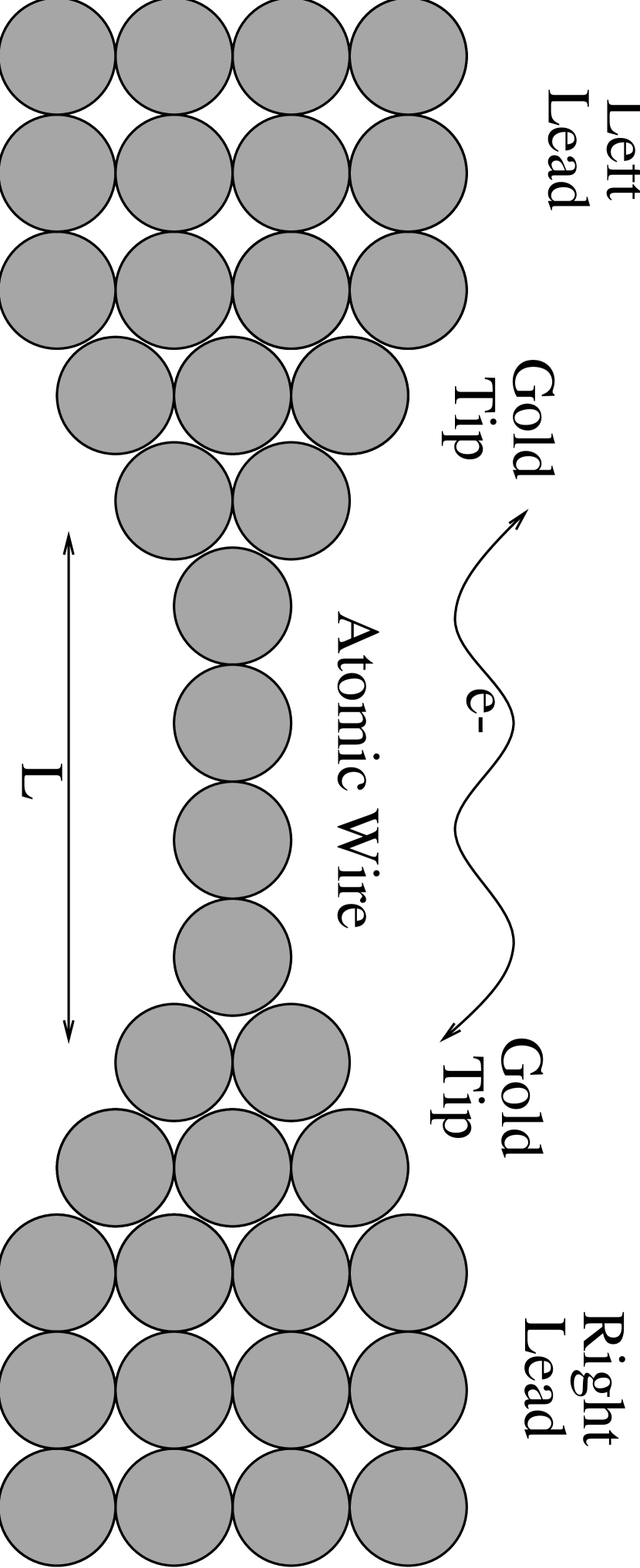
We calculate the multi-channel transmission probability by solving for the matrix of the atomic wire system. For a given energy , an electron can propagate in one of many electronic modes in both the source and the drain. The matrix connects the modes (or channels) in the source to the channels in the drain for a given energy. We use a tight-binding treatment of Schrödinger’s equation to set up a system of linear equations to solve for . The source and drain are treated as 1D leads with multi-atom unit cells. The wire is attached to atomic tips which are then attached to the leads. An schematic diagram of an atomic wire system is shown in Fig. 1.
The first step in the transport calculation is to impose boundary conditions on the wavefunction which describes an electron incident in the channel with energy . In the source (or left lead (L)) consists of the incident rightward propagating (+) Bloch mode along with a sum over reflected leftward propagating (-) and evanescent modes . On the atomic wire (A), the wavefunction is a sum over the atomic orbitals that exist on the wire. In the drain (or right lead (R)) the wavefunction is a sum over the transmitted rightward propagating and evanescent modes . Thus the wavefunction is given by,
| (1) |
where
| (2) | |||||
| (3) | |||||
| (4) |
Using Schrödinger’s equation , where is the extended Hückel tight binding Hamiltonian[20] of the system, yields a system of equations which we solve to find the ’s, ’s and ’s. With the matrix thus determined, the transmission probability is then found using
| (5) |
where the sum over is over the rightward propagating modes in the left lead and the sum over is over rightward propagating modes in the right lead. The velocity ratio appears since the velocities of modes in the left and right leads may be different. The conductance is then found by using the Landauer formula given above for the transmission probability evaluated at the Fermi energy of the source. This method and the procedure used for handling the non-orthogonality between the different tight-binding orbitals is described in more detail elsewhere.[16, 21]
The above tight-binding model is completely general and is applicable to many types of systems, not just atomic wires. We now proceed to examine the physical behaviour the above model should exhibit when applied to a 1D constriction such as an atomic wire. The physical interpretation that we will use to describe the results of our transport calculations that follow is in terms of electronic standing waves formed within the constriction.
When waves (be they light, sound or electron) are confined to propagate within a finite one dimensional channel, standing waves are formed. They are formed due to the interference of waves back reflected from the ends of the pipe where there is a large impedance mismatch. These standing waves (also known as normal modes) have an associated wave vector given by where labels the normal mode and is the effective length of the channel. Within the tight binding framework, for a 1D channel composed of a finite chain of discrete atoms equally spaced by a distance , the number of normal modes becomes finite. The reduced wavevector of the wave is and has the range . Thus must be less than or equal to which restricts the values that can take. Thus a finite chain supports only a finite number of standing waves.
In regards to electron transport, when an electron is incident from the source with an energy that corresponds to the energy of one of the normal modes, it will form a standing wave along the chain. This will correspond to maximal transmission through the atomic wire. Because the chain supports a finite number of normal modes the transmission probability will have a discrete number of resonances, each one corresponding to one of the normal modes.
The effective length of the atomic wire determines the number of resonances in the transmission probability. Intuitively this length should approximate the contact-to-contact distance. However, an effective length which may be shorter or longer than the contact-to-contact spacing will occur in practice. This depends on the chemical and geometrical nature of the interface between the atomic chain and the metallic contacts. The chemistry may serve to effectively sharpen or broaden the constriction which will affect the effective length. For a homogeneous atomic wire system where the contacts and the chain are made of the same atoms, the length of the wire should be approximately equal to the contact-to-contact distance. In this situation the confining potential is that created by the geometry of the constriction and hence the backscattering should occur at the interface between the contacts and the chain where the impedance mismatch is high. For heterogeneous systems, the length may be different from the contact-to-contact length. This is because the chemistry between the chain and the contact is significantly different than that within the bulk of the contact. Thus the confining potential due to the geometry is now altered. An interface region is created which modifies the confining potential and this changes the effective length of the chain. So in heterogeneous wires one may expect there to be more or fewer resonances than in the homogeneous case.
III Homogeneous Wire: Gold Wire with Gold Contacts
The first system we consider is a homogeneous atomic wire of gold. An atomistic diagram of one of the wires is shown in Fig. 1. The atomic chain is made up of gold atoms with a spacing of 2.4 Å. The chain is bonded over two gold tips, each consisting of 13 gold atoms and both oriented in the (100) direction. The perpendicular bonding distance between the chain and a tip is taken to be 2.0 Å. Each tip is then bonded to a layer of 16 gold atoms which forms the unit cell for the contact. The gold atoms along the chain and the four gold atoms in each tip to which the chain is attached are modeled using the 6 s6 p5 d orbitals of gold. The remaining gold atoms in the tips and those in the leads are modeled using a 6 s orbital. We consider chains ranging in length from 3 to 7 gold atoms.
The transmission probabilities for the five different chain lengths are shown in Fig. 2. As expected there is a different number of resonances for each chain length. For the energies shown, only a 6 s mode is supported by the chain and hence the maximum value that the transmission probability can take is 1 (ignoring spin). If there were more modes which could propagate along the chain the multi-channel Landauer transmission probability could be greater than 1. Since the gold atomic wires are a homogeneous system the length corresponds approximately to the contact-to-contact spacing which is roughly where is the number of atoms forming the chain and Å. So an atom chain should display resonances and this is seen. (One might argue that there should be resonances, but the wavefunction that corresponds to this value has a node on each atomic site and hence is unphysical). The or last resonance of each chain (which is not shown) has an energy that lies between -6.5 eV and -5.5 eV and this overlaps some 6 p modes which also contribute to the transmission and obscure this resonance.
At each resonance the electron wavefunction is a standing wave along the 6 s orbital backbone of the chain. The squared modulus should behave as where is the position coordinate along the wire ( marks the first chain atom), is the leftmost position where the wavefunction is zero (this may extend beyond the chain into the tips) and labels the mode. The wavefunction (calculated using our tight-binding model) for the 5 atom chain is plotted for the and resonance together with the corresponding ideal sinusoidal standing waveform in Fig. 3a. The graphs clearly indicate the formation of standing waves along the chain. The length which best fits the data is around 13Åwhich is just slightly shorter than the 13.6Åcontact-to-contact spacing for this chain. In Fig. 4a the behaviour of the wavefunction in the gold tips for the mode is depicted for the 5 atom chain. The atoms in the tips fall outside the length of the ”pipe” and thus are not part of the standing wave formation within the pipe. The wavefunction is consistently larger within the left tip than on the right as is to be expected for a wave incident on the wire from the left contact. (Note that the squared wavefunction that is depicted is a qualitative result and should not be compared to the transmission results. What is shown is the result of adding together the squared amplitude of the wavefunction for each incident channel. Thus it is the “average” wavefunction along the atomic chain.)
The conductance of these chains is given by the Landauer formula, . The transmission probability that enters the Landauer expression is evaluated at the source Fermi energy. For our gold leads the Fermi energy is approximately -10 eV. Fig. 6a shows the conductance as a function of the number of atoms in the wire at this Fermi energy. In qualitative agreement with experiment[8] the conductance is nearly unity and varies between 0.81 and 0.99 . The fluctuations are relatively small because the peak to valley ratio of the transmission probability near the Fermi energy is near unity for the different gold chains.
IV Heterogeneous Wire: Carbon Wire Results
The second structure that we consider is a heterogeneous system consisting of a carbon atomic wire and gold contacts. The atomic system is similar to that depicted in Fig. 1. The carbon chain spacing is taken to be 1.32Å. Again it is bonded over 13-atom gold tips oriented in the (100) direction. The perpendicular bond distance between the chain and a tip was chosen to be 1Å. The four gold atoms that bond to the carbon wire on each tip were simulated using their 6 s6 p5 d orbitals while the other gold atoms were simulated using just their 6 s orbital. (We remark that the results obtained modelling all of the gold atoms in this system with only 6s orbitals were qualitatively similar.) The carbon atoms were simulated using their 2 s and 2 p orbitals. Chains consisting of 4 to 10 carbon atoms were simulated.
The transmission probabilities for chains numbering 4 through 8 are shown in Fig. 5. The magnitude is greater than that found in the gold chains with a maximum value of near 2.0. This is because for these energies the electrons are propagating along the backbone of the carbon wire. If the wire is oriented along the direction there are two independent modes ( and ) along which the electrons can propagate. Thus the transmission can be a maximum of 2.0 (ignoring spin). In those regions where it exceeds 2.0, an extra mode is present. The number of resonances for a given numbered carbon chain is also greater than that of the corresponding gold chain. For heterogeneous systems the chemistry at the interface between the atomic wire and the metallic contacts effectively alters the length of the 1D conducting channel. For example the 4 atom carbon chain displays 6 resonances which shows that the interaction is such that it is effectively lengthened and behaves like a 6 atom chain.
To determine what the effective length for one of these carbon chains is we examine the electron’s wavefunction. The wavefunctions for two different resonances of the 5 atom carbon chain are plotted in Fig. 3b. The corresponding normal modes are also plotted where was chosen so as to give a best fit to all the curves. The value of was determined to be around 10.0Åwhich is significantly longer than the contact-to-contact distance of 7.28Å. From this we can estimate that the interface region extends about 1.36Åinto the gold tip. So in this system the standing waves are forming from within the gold tips rather than at their surfaces as was the case for the gold atom wires. The behaviour of the wavefunction in the tips is depicted in Fig. 4b. It is seen that the standing wave continues onto the first layer of each tip. However, the wavefunction on the second atomic layer of each tip lies outside the length and resembles the behavior of the wavefunction within the tips of the gold atomic wire. It is seen that the wavefunction on the left tip is greater than that on the right. Again, we emphasize that we are using the “average” wavefunction to perform this analysis.
The conductance of these carbon chains was found using the same source Fermi energy of -10 eV. Conductance oscillations are found for this choice as the number of carbon atoms in the chain is varied, with odd numbered chains possessing a higher conductance than even ones (shown in Fig. 6b). This is consistent with other theoretical work which has also found conductance oscillations as a function of carbon wire length although the carbon wire and contacts were modelled in a different way in that work.[12] The oscillation has quite a strong signature with the conductance varying between 0.9 and 1.8 . For the odd numbered chains the conductance is large because the Fermi energy corresponds to a standing wave resonance, whereas the even numbered chains are off resonance. The standing wave interpretation seems to be a reasonable physical interpretation for the oscillating conductance found here and in a previous report.[12]
V Conclusions
We have shown that electron transport through an atomic wire is consistent with the interpretation that electron standing waves are formed in the atomic wire which bridges metallic contacts. They arise because of the interference of reflected electron waves at the interface between the atomic chain and the metallic tips. For the gold tips the effective length of the constriction was roughly the contact-to-contact distance. The conductance of the gold wires was also found to be near unity for atomic wires ranging from 3 to 7 gold atoms, consistent with experiment. The behavior in the carbon wires was different. The effective length of the constriction was significantly larger signalling that the formation of standing waves is sensitive to the chemistry of the atomic wire-contact interface. The conductance was also found to oscillate as a function of chain length and this can be understood in terms of the different standing wave modes that are created in chains of differing length. The observation of electron standing waves may be facilitated by using atomic wires (as opposed to semiconductor systems) since the constriction can not be smooth, which will enhance the reflections.
This work was supported by NSERC.
REFERENCES
- [1] B. C. Stipe, M. A. Resaei, W. Ho, Science 280, 1732 (1998).
- [2] P. S. Weiss, H. Yokota, D. L. Allara, J. Phys. Cond. Matt. 10, 7703 (1998).
- [3] J. Gimzewski, Phys. World 11, 29 (1998).
- [4] R. P. Andres, J. D. Bielefeld, J. I. Henderson, D. B. Janes, V. R. Kolagunta, C. P. Kubiak, W. J. Mahoney, and R. G. Osifchin, Science 273, 1690 (1996).
- [5] L. A. Bumm, J. J. Arnold, M. T. Cygan, T. D. Dunbar, T. P. Burgin, L. Jones II, D. L. Allara, J. M. Tour, P. S. Weiss, Science 271, 1705 (1996).
- [6] Y. Kawahito, H. Kasai, A. Okiji, Surf. Sci. 409, L709 (1998).
- [7] A. Yazdani, D. M. Eigler, N. D. Lang, Science 272, 1921 (1996).
- [8] A. I. Yanson, G. R. Bollinger, J. M. van Ruitenbeek, Nature 395, 783 (1998).
- [9] D. Pierson, C. Richardson, B. Yakobson, unpublished (1998).
- [10] M. Yu, M. J. Dyerb, H. Rohrsa, X. Lua, K. Ausmana, J. Von Ehr, R. S. Ruoff, unpublished (1998)
- [11] V. Mujica, M. Kemp, M. A. Ratner, J. Chem. Phys. 101, 6856 (1994).
- [12] N. D. Lang, Ph. Avouris, Phys. Rev. Lett. 81, 3515 (1998).
- [13] G. Kirczenow, Solid State Commun. 68, 715 (1988), J. Phys. Cond. Matt. 1, 305 (1989), Phys. Rev. B 39, 10452 (1989); A. Szafer and A. D. Stone, Phys. Rev. Lett. 62, 300 (1989); E. Haanappel and D. van der Marel, Phys. Rev. B 39, 5484 (1989); L. Escapa and N. García, J. Phys. Cond. Matt. 1, 2125 (1989); E. Tekman and S. Ciraçi, Phys. Rev. B39, 8772(1989); Y. Avishai and Y. B. Band, Phys Rev B40, 12535(1989);
- [14] L. I. Glazman et al., JETP Lett. 48, 238 (1988); A. Szafer and A. D. Stone, Phys. Rev. Lett. 62, 300 (1989); E. Tekman and S. Ciraçi, Phys. Rev. B39, 8772(1989); E. Castaño and G. Kirczenow, Phys. Rev. B45, 1514 (1992).
- [15] For a review see S. E. Ulloa, A. Mackinnon, E. Castano, G. Kirczenow, Basic Properties of Semiconductors, v. 1, sec. 4.1.2, Elsevier Science Publishers, 1992.
- [16] E. Emberly and G. Kirczenow, Phys. Rev. B 58, 10911 (1998).
- [17] M. P. Samanta, W. Tian, S. Datta, J. I. Henderson, and C. P. Kubiak, Phys. Rev. B 53, R7626 (1996).
- [18] C. Joachim, and J. F. Vinuesa, Europhys. Lett. 33, 635 (1996).
- [19] R. Landauer, IBM J. Res. Dev. 1, 223 (1957); R. Landauer, Phys. Lett. 85A, 91 (1981).
- [20] R. J. Hoffmann, J. Chem. Phys. 39, 1397 (1963).
- [21] E. Emberly and G. Kirczenow, Phys. Rev. Lett. 81, 5205 (1998). E. Emberly and G. Kirczenow, unpublished (1999).