Central peak position in magnetization loops of high- superconductors
Abstract
Exact analytical results are obtained for the magnetization of a superconducting thin strip with a general behavior of the critical current density. We show that within the critical-state model the magnetization as function of applied field, , has an extremum located exactly at . This result is in excellent agreement with presented experimental data for a YBa2Cu3O7-δ thin film. After introducing granularity by patterning the film, the central peak becomes shifted to positive fields, , on the descending field branch of the loop. Our results show that a positive is a definite signature of granularity in superconductors.
pacs:
PACS numbers: 74.25.Ha, 74.76.Bz, 74.80.BjThe investigation of magnetic hysteresis loops (MHLs) is a widely used tool to characterize superconducting samples, and in particular, to estimate the critical current density and its dependence on magnetic field. An ever-present feature of the MHLs is a peak in the magnetization located at an applied field near zero. The central peak is formed due to a field dependence of the critical current density, , monotonously decreasing at small fields. When the sample is a long cylindrical body placed in a parallel applied field, the peak position can be calculated analytically within the critical-state model for several dependences [2]. One always finds on the descending field branch that , and similarly on the ascending branch of large-field loops. In simple terms the shift is a consequence of the local flux density, , lagging behind the applied field.
Also experimentally there are abundant observations of negative on the descending field branch. However, in some cases one finds very close to zero or even shifted to the positive side so that the peak occurs before the remanent state is reached [3, 4, 5, 6, 7]. The explanations for this behavior are controversial. On one hand, a decreasing sample thickness is known from experiment to shift the peak toward [8, 9]. This is also in agreement with recent numerical results obtained for the critical-state model with -dependent [9, 10]. However, the numerical calculations have not predicted sufficiently large shifts to bring the peak to the anomalous side of the loop.
A different explanation of the shift in was suggested for granular materials, [11] where a demagnetization effect of the grains can be important. The magnetization of a granular superconductor is determined by both intra- and inter-grain currents. The latter represent large-size current loops, and can give a major contribution to the magnetic moment. These inter-grain currents are essentially determined by the magnetic field just at the grain boundaries. Those local fields are, in turn, strongly influenced by the intra-grain currents, and can vary ahead of the local expected without granularity. As a result, the central peak is encountered earlier in the MHL. Models allowing quantitative MHL calculations with account of the grain-induced demagnetization effect [5, 12] successfully reproduced the peak at .
Although the significant influence of both sample shape and sample granularity on the MHL is generally recognized, the interplay between them has never been addressed. In particular, it is not known if a positive is accessible for thin enough samples, or if on the descending field branch is a definite signature of sample granularity. The present work aims to answer this question. We show first analytically that for any the central peak is located exactly at for a thin uniform strip, a result we also confirm by experiment. The key role of granularity is then demonstrated by measurements on an artificially granular thin film, where we find .

Consider a long thin superconducting strip with edges located at , the -axis pointing along the strip, and the -axis normal to the strip plane, see Fig. 1. The magnetic field, , is applied along the -axis, so screening currents flow in the -direction. Throughout the paper is the -component of magnetic induction in the strip plane. The sheet current is defined as , where is the current density and the integration is performed over the strip thickness, .
From the Biot-Savart law for the strip geometry, the flux density is given by [13]
| (1) |
Assume that the strip is in a fully penetrated state, i.e., the current density is everywhere equal to the critical one, . This state can be reached after applying a very large field, and then reducing it to some much smaller value. The field distribution then satisfies the following integral equation,
| (2) |
In the remanent state, , the flux density profile has an interesting symmetry. This is seen by changing the integration variable in Eq. (2) from to . We then obtain
| (3) |
Substituting into Eq. (2) one obtains a similar equation for ,
| (4) |
By comparing equations (3) and (4) at we conclude that
| (5) |
is generally valid if depends only on the absolute value of the magnetic induction, . This symmetry is immediately evident for the case const., i.e., the Bean model, when Eq. (2) reduces to
| (6) |
In a similar way one can prove also another symmetry relation valid at , namely
| (7) |
where .
Consider now the magnetic moment per unit length of the strip, . Differentiating with respect to and taking into account that changes sign at one has after splitting the integral into two parts
| (8) |
Then, replacing in the second integral by and using Eq. (5), we come to
| (9) |
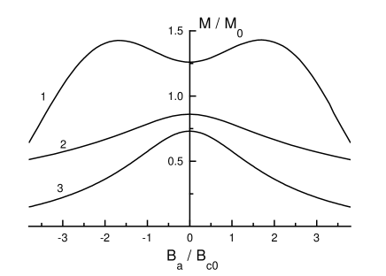
Consequently, on a major MHL the magnetic moment has an extremum in the remanent state for any -dependence. This is illustrated in Fig. 2 showing the central part of MHLs obtained by an iterative numerical solution of Eq. (2) for three dependences. The extremum depends on the type of dependence. It is a maximum for a decreasing , and a minimum if has a pronounced second peak, the so-called fishtail behavior.
Two YBa2Cu3O7-δ epitaxial thin films were chosen for a comparative study; (A) a uniform film of regular shape, and (B) a film with artificial granularity. Sample (A) was prepared by laser ablation on an MgO substrate [14]. The thickness was 200 nm, and the sample was patterned by chemical etching into a rectangular shape of dimensions 0.66 1.4 mm2. The homogeneity of the sample was tested by magneto-optical imaging, where it showed complete absence of any visible defects [15].
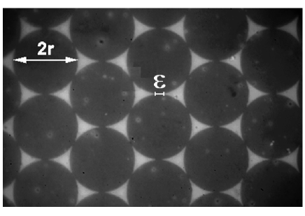
Sample (B) was laser ablated to a 150 nm thickness on a LaAlO3 substrate. The film was patterned by means of electron beam lithography into a hexagonal close-packed lattice of disks with m diameter. The disks are touching each other at the circumferences in order to enable the flow of inter-disk currents. The width of the contact region is m, see Fig. 3. The superconducting disks can be considered as grains and the connections between them as inter-grain junctions. The overall size of the sample was 44 mm2, comprising disks. The transition temperature after the patterning process is 83 K.
The magnetization measurements were performed using a vibrating sample magnetometer (VSM) PAR Model 155 with computerized control and data processing. The magnetic field is generated by a conventional magnet with 2 T. The field was applied parallel to the axis, which is perpendicular to the film plane. The magnetization loops were always measured after zero-field cooling of the sample. The maximum applied field for all measurements was significantly higher than the field giving a fully penetrated state, as verified by the magneto-optical method. To focus on our main issue, only the data measured on the descending field branch of the MHLs near are presented.
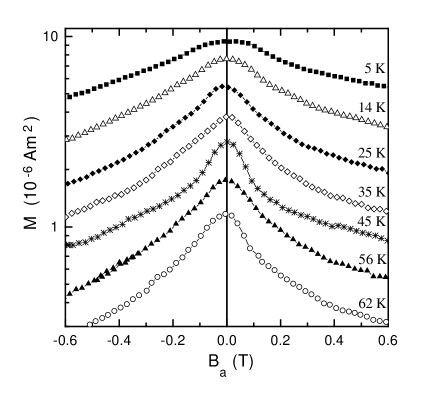
Figure 4 shows the central part of the MHLs for the uniform film (A). The measurements were carried out over a wide range of temperatures in order to probe different dependences. There is evidently here a pronounced central peak at all temperatures. Within the experimental resolution the position of the peak is located at zero applied field. The observation that the peak remains at over the entire temperature range is in full agreement with our general analytical result.
Note that the result was derived for an infinite strip fully penetrated by the magnetic field. In a thin sample, in contrast to long cylinders, the flux fronts move in response to a changing applied field at an exponential rate [13]. Therefore, a fully remagnetized state is reached quickly after reversing the direction of a field sweep, and our experimental conditions are consistent with the assumptions made in the theory. The only exception is the finite length of the strip. However, our results show that it is not a crucial factor for the peak position.
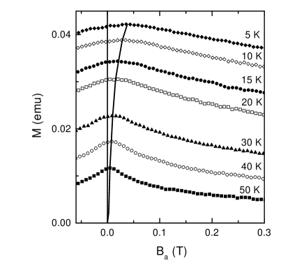
The MHLs for the sample (B) with artificial granularity are shown in Fig. 5. The central peak displays here different behaviour as compared to the uniform film (A). For all temperatures on the descending field branch. The shift of the central peak becomes more and more pronounced with decreasing temperature reaching mT at K.
In this sample, the “grains” and their interconnections are of the same material, and hence have equal critical current density. Due to the patterning, the spatially averaged inter-grain current density is less than the current density, , of the superconducting material itself. For the hexagonal pattern, see Fig. 3, one has , where depends on the direction of , within the limits . Futhermore, the magnetic moment due to intra-grain currents and moment due to inter-grain currents are related as
where is the overall size of the sample. In the present case this ratio is 1/6, showing that the inter-grain contribution to the total magnetic moment is dominant. A considerable grain-induced demagnetization effect is therefore expected for this sample. Its granularity, being the only essential difference from the uniform film, is the only possible origin of the observed shift to .
The superconducting Bi-2223 tapes are known to have a granular microstructure and the two contributions to the magnetic moment are of comparable magnitude [5]. The grain demagnetization effect has been suggested as an explanation for the observed shift of the peak to on the descending MHL branch in these materials [4, 5, 6, 7]. Our present results give strong support to this physical picture.
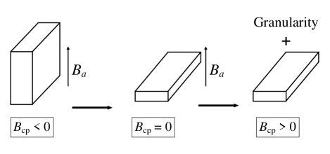
In conclusion, we arrive at a following general scenario concerning the central peak position, see Fig. 6. Long samples in parallel magnetic field show in their MHLs a central peak at a negative applied field, i.e. after passing through the remanent state on the descending field branch. As the sample thickness decreases the peak position is shifted towards zero. It is located exactly at , in the limiting case of a uniform strip of infinitessimal thickness. Granularity always leads to a shift of in the positive direction on the descending field branch. Thus, for a granular thin strip the peak is located at a positive field, i.e., before the remanent state is reached. The origin of this effect is that granularity induces demagnetization fields which strongly modify the inter-granular currents via their -dependence.
We thank Y. Shen (NKT Research Centre, Brøndby, Denmark) for the excellent uniform YBCO thin film as well as B. Nilsson and T. Claeson (Chalmers, Gøteborg, Sweden) for the film with artificial granularity. We acknowledge valuable discussions with Prof. M. Murakami (SRL/ISTEC, Div. 3, Tokyo, Japan) and L. Pust (Wayne State University, Detroit, USA). The financial support from the Research Council of Norway, from the Russian National Program for Superconductivity, and from the grant No. A1010512 of GA ASCR is gratefully acknowledged.
REFERENCES
- [1] Present address: Superconducting Research Laboratory, ISTEC, Division 3, 1-16-25, Shibaura, Minato-ku, Tokyo 105, Japan
- [2] D.-X. Chen and R. B. Goldfarb, J. Appl. Phys. 66, 2489 (1989); P. O. Hetland, T. H. Johansen and H. Bratsberg, Appl. Supercond. 3, 585 (1995); T. H. Johansen and H. Bratsberg, J. Appl. Phys. 77, 3945 (1995).
- [3] M. E. McHenry, M. P. Maley, and J. O. Willis, Phys. Rev. B 40, 2666 (1989).
- [4] M. R. Cimberle, C. Ferdeghini, R. Flükiger, E. Giannini, G. Grasso, D. Marrè, M. Putti, and A. S. Siri, Physica C 251, 61 (1995).
- [5] K.-H. Müller, C. Andrikidis, Y. C. Guo, Phys. Rev. B 55, 630 (1997); K.-H. Müller, C. Andrikidis, H. K. Liu, and S. X. Dou, Phys. Rev. B 50, 10218 (1994).
- [6] M. R. Koblischka, L. Pust, A. Galkin and P. Nalevka, Appl. Phys. Lett. 70, 514 (1997).
- [7] M. R. Koblischka, T. H. Johansen, and H. Bratsberg, L. Pust, A. Galkin, P. Nalevka, M. Marysko, M. Jirsa, M. Bentzon, P.Bodin, P. Vase, and T. Freltoft, J. Appl. Phys. 83, 6798 (1998).
- [8] M. Däumling, E. Walker, and R. Flükiger, Phys. Rev. B 50, 13024 (1994); S. B. Roy, A. K. Pradhan, and P. Chaddah, Physica C 250, 191 (1995).
- [9] M. Däumling, and W. Goldacker, Z. Phys. B 102, 331 (1997).
- [10] J. McDonald and J. R. Clem, Phys. Rev. B 53, 8643 (1996); K. V. Bhagwat and P. Chaddah, Physica C 224, 155 (1994).
- [11] J. E. Evetts and B. A. Glowacki, Cryogenics 28, 641 (1988).
- [12] A. I. D’yachenko and J. Stankowski, Fiz. Nizk. Temper. 22, 635 (1996); A. I. D’yachenko, Physica C 213, 167 (1993).
- [13] E. H. Brandt, and M. Indenbom, Phys. Rev. B 48, 12893 (1993); E. Zeldov, J. R. Clem, M. McElfresh, and M. Darwin, Phys. Rev. B 49, 9802 (1994).
- [14] P. Vase, Y. Shen, and T. Freltoft, Physica C 180, 90 (1991).
- [15] M. R. Koblischka, T. H. Johansen, H. Bratsberg, L. Pust, Y. Shen, and P. Vase, J. Phys.: Condens. Matter 9, 10909 (1997).