[
Properties of SAS Josephson junctions in SO(5) theory.
Abstract
We derive the qualitative behavior of superconductor-antiferromagnet-superconductor (SAS) Josephson junctions described by Zhang’s SO(5) theory. The main differences between these junctions and conventional SIS junctions arise from the non-sinusoidal current-phase relation derived by Demler et al. for thin SAS junctions. Using a simple approximation to this non-sinusoidal function, the current voltage relation, Shapiro steps, thermal fluctuation effects and the diffraction pattern in a magnetic field are obtained.
]
Recently there has been considerable attention focused on the theory of Zhang [1], which attempts to unify the d-wave superconductivity in doped Mott insulators with the antiferromagnetism of undoped “parent” compounds. In this theory, the antiferromagnetic Néel vector and the complex superconducting order parameter form the components of a 5-dimensional “superspin” vector. The SO(5) rotational symmetry of the superspin is explicitly broken by anisotropy which favors antiferromagnetism for undoped or lightly-doped compounds and superconductivity for more heavily doped materials. The transition from antiferromagnetism (A) to d-wave superconductivity (S) is analogous to the spin-flop transition of a uniaxial Heisenberg antiferromagnet in a parallel magnetic field.
From a phenomenological perspective, the most striking manifestations of this theory arise in situations where the SO(5) order parameter can be rotated from S to A or vice-versa by some kind of external field. One way of imposing such a field is by proximity to a material in which the superspin direction is strongly anchored, such as in the superconductor-antiferromagnet-superconductor (SAS) heterostructure proposed by Demler et al. [2]. Here we study the properties of such a heterostructure in the presence of an external circuit and magnetic field. Our analysis, based upon the SAS Josephson current-phase relation obtained within SO(5) theory[2], has the potential to provide a series of qualitative tests for the applicability of this theory to doped Mott insulators.
The device proposed by Demler et al. consists of a thin antiferromagnetic layer sandwiched between two strongly superconducting regions (see inset in Fig. 1). If the anisotropy stabilizing the antiferromagnetism in the A region is weak, the proximity effect of the S regions will align the order parameter uniformly in the S direction. For the A region, there is a critical thickness , below which it remains purely superconducting. For thicknesses , the order parameter in the A region tips toward the A direction, with maximum tipping angle at the cen-
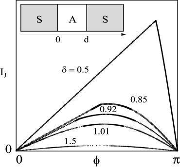
ter of the region, and the current-phase relation of junctions is similar to that of conventional SIS junctions. For , a tipping transition occurs at a critical value of the supercurrent or, equivalently, of the superconducting phase difference across the junction. As the phase difference is varied through the critical value , the slope of the current-phase relation changes discontinuously, from linear in the superconducting regime for to roughly sinusoidal for where the order parameter in the A layer tips toward the A direction.
The current-phase relation calculated in Ref. [2] and shown in Fig. 1, can be approximated by
| (1) |
where defines the discontinuity in the derivative of the current-phase relation and , while and , the antiferromagnetic coherence length. It should be emphasized that although is a useful parameter for identifying a variety of physical effects in the SAS junction, it can be related to more physical quantities. Indeed one can show that
| (2) |
A useful way of comparing theoretical predictions of junction behavior to existing or future experimental data, is to analyze the behavior of the junction within a circuit, the classic system being the Resistively and Capacitatively Shunted Josephson (RCSJ) Junction[3]. Here the junction is placed in parallel with a capacitor and resistance and a constant current is passed through the circuit. Such a model takes into account the capacitive effects of the junction and also single particle tunneling which produces a normal state resistance. In the following, we explore the properties of the SAS junction, using the current-phase relation of Eq. (1) in an overdamped circuit where capacitive effects are assumed to be negligible, and we contrast these properties to those of conventional SIS junctions which obey a sinusoidal current phase relationship (SCPR), given by Eq. (1) with .
The dynamics of the overdamped SAS junction (ignoring thermal effects) are governed by the equation
| (3) |
where is the resistance produced by single quasiparticle tunneling and is an externally applied dc current. From Eq. (3) it is straightforward to derive the dc I-V characteristic of the SAS junction from the Josephson equation where is the induced time dependent voltage:
| (4) |
A dc voltage is not induced in the system unless the driving current is greater than , the maximum of the Josephson current [4]. However, unlike a junction with a SCPR, the SAS system exhibits two distinct conditions for this to occur, depending on the junction thickness. For a thin junction with , the minimum current required to induce a dc voltage is , while for a thick junction with , a dc voltage appears only for .
For an SAS system with , in the region , the dc voltage is given by
| (5) | |||||
| (6) | |||||
| (7) |

where , while in an SAS system with , irrespective of the analogous result is
| (8) | |||||
| (9) | |||||
| (10) |
There are several comments to be made on the two expressions above. For a junction with a SCPR, the I-V relation has the form [5], which is finite for , and shows ohmic behavior as the driving current becomes large. For , Eq. (8) reduces to this form, since in this limit the SAS current-phase relation is well approximated by the normal Josephson expression. On the other hand, there is a clear qualitative difference between Eqs. (5) and (8) as becomes larger. For , as , tends to zero logarithmically. This implies that as the driving current is increased from zero, there should be a very rapid increase in the induced dc voltage as soon as rises above .
By plotting against , and relating to through Eq. (2), we can compare I-V curves for SAS systems of various barrier widths. This comparison is shown in the inset of Fig. 2. Note that as , the I-V curve becomes identical to that of a regular junction with a SCPR. On the other hand, as the barrier width becomes narrower, the dc voltage develops a sharp (logarithmic) leading edge and clearly deviates from nor-
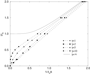
mal junction behavior. These differences will show up most clearly in the differential resistivity. In the body of Fig. 2 we plot the difference between I-V curves of the SAS junction and the normal junction, defined as . The maximum deviation from normal junction behavior occurs when the driving current is just above the threshold current .
Thermal effects lower the threshold current to zero, interpolating between the behavior and a linear I-V relation as was shown by Ambegaokar and Halperin [6]. The analogous results are shown in Fig. 3 for a thin SAS junction [7]. Comparison to Ref. [6] shows that the largest differences between SAS and conventional junctions occur at low temperatures and small voltages.
The addition of an ac component to the dc driving current produces Shapiro steps[8] in the I-V characteristics of RCSJ systems at certain values of the dc voltage [9]. These steps of constant dc voltage for a range of values of the dc driving current can be understood as arising from phase-locking between the fundamental Josephson frequency of the junction or one of its harmonics and a harmonic of the applied ac current. This leads us to consider the addition of an ac driving current to the SAS system described above, since the unusual form of the current-phase relation may lead to features within the step structure of the dc I-V characteristic. In particular, the time dependent current induced in the SAS junction from the purely dc driving current, should have a rich harmonic structure which can respond to the harmonics of the additional ac current.
In order to explore this point, we add to the right hand side of Eq. (3) an applied current of the form . By making a change of variables and defining where the subscript , the dynamics of our circuit can be described by
| (11) |
which can be solved numerically to obtain as a function of , for fixed values of and . Steps are expected to occur when () [9], where is a non-negative integer. This corresponds to the previously mentioned phase-locking between the fundamental Josephson frequency and a harmonic of the applied ac current. In addition, sub-steps should appear when , due to phase-locking between harmonics of the Josephson frequency and the applied ac current frequency.
From our numerical analysis of Eq. (11), we show in the inset of Fig. 4 a typical stepped I-V characteristic for a narrow () SAS junction with parameters and . The body of Fig. 4 shows the change in step-heights as the ac driving current amplitude is varied (dashed lines). The zeroth step-height is defined as the value of at which becomes non-zero, while the first step-height is simply the length of the vertical step at , and so on (see inset). When , the zeroth step-height is simply given by , where is the threshold current required to induce a dc voltage as defined earlier. In this figure we also compare the zeroth and first step-heights of the SAS junction to a normal junction with a SCPR and the same value of (solid lines).
There are several distinct features which distinguish the SAS Shapiro step behavior from that of a regular Josephson system. As can be seen in the figure, there is a clear linear behavior in the zeroth step-height for small values of for the SAS junction. For a junction with a SCPR, the step-height dependence on has a quasi-Bessel function behavior where the Bessel function is of the same order as the step-height [9, 10]. For the SAS junction, it would appear that the higher harmonic con-

tent of (Eq. 1), allows phase-locking to occur for all values of , in contrast to a regular junction with a SCPR, where there are zeroes in the step-heights for certain values of . Furthermore, the maxima of the step-heights are suppressed for the case, and there appears to be a slight shift in the periodicity of the step-height behavior. It is worth noting too, that from the higher harmonic content of the SAS current phase relation, there are large step-heights (sub-steps) at non-integer values of . These are enhanced over what would be expected in the Shapiro steps produced by a regular junction with a SCPR.
As a last illustration of the properties of SAS junctions, we consider the isolated junction in the presence of a magnetic field. A magnetic field will produce Fraunhofer diffraction peaks for the maximum current through an SAS junction as a function of the magnetic flux threading through it. For the SAS junction in a magnetic field, we consider the system to be lying flat along the -axis with thickness , a height along the -axis and a depth parallel to the -axis. Applying a magnetic field along the positive direction implies that the gauge-invariant superconducting phase difference across the junction is given by , where is the phase difference at one end of the junction and is the flux quantum [11]. In general, the current, through the junction will be given by where the integrand is the current density . For a junction with , one can show that the current is given by
| (12) |
where is the magnetic flux threading the junction. The maximal current is obtained by maximizing with respect to . This leads to the following equation for ,
| (13) |
On the other hand, for a junction with , is given by the regular Fraunhofer expression for , and then is determined by Eqs. (12) and (13) for .
We have determined the maximal current through the SAS junction as a function of magnetic flux by systematically solving Eqs. (12) and (13) for increasing values of the magnetic flux ratio . In Fig. 5 we show the variation of with the magnetic flux ratio for a variety of SAS barrier thicknesses. Fig. 5 shows a general suppression of the diffraction peaks and a strong linear dependence before the first diffraction minimum, reminiscent of the Shapiro step-height behavior.
In summary, we propose that the existence of an SO(5) superspin vector can be inferred from distinctive features

of an overdamped SAS junction, particularly the rapid increase of the voltage in the low T I-V curve, the linear dependence of Shapiro step heights as a function of ac driving current, and the linear dependence of the critical current at low magnetic fields.
The authors would like to thank E. Demler for useful discussions. This work was supported in part by the Natural Sciences and Engineering Research Council of Canada, by the Ontario Center for Materials Research and by Materials and Manufacturing Ontario. BCdH would like to thank the BIMR, McMaster University for their hospitality during the period of this work.
REFERENCES
- [1] S. C. Zhang, Science 275, 1089 (1997).
- [2] E. Demler, A.J. Berlinsky, C. Kallin, G.B. Arnold and M.R. Beasley, Phys. Rev. Lett. 80, 2917 (1998).
- [3] See A. Barone and G. Paterno, Physics and Applications of the Josephson Effect (Wiley & Sons, New York 1982).
- [4] This is simply the analogy of a massless particle moving along the axis in a potential defined by . For , there will be a local minimum where the particle will come to rest.
- [5] L. G. Aslamazov, A.I. Larkin and Yu. N. Ovchinnikov JETP 28, 171 (1969). D. E. McCumber, J. Appl. Phys. 39, 3113 (1968).
- [6] V. Ambegaokar and B. J. Halperin, Phys. Rev. Lett. 22, 1364 (1969).
- [7] The related problem of a thin superconducting wire in SO(5) theory has been studied by D. E. Sheehy and P. M. Goldbart, Phys. Rev. B 57, R8131 (1998).
- [8] S. Shapiro, Phys. Rev. Lett. 11, 80 (1963).
- [9] J. R. Waldram, A. B. Pippard and J. Clarke, Philos. Trans. R. Soc. Lond. A 269, 265 (1970).
- [10] P. Russer, J. Appl. Phys. 43, 2008 (1972).
- [11] M. Tinkham, Introduction to Superconductivity, (McGraw Hill, New York, 1996).