Spin- Flip Torsion Balance
Abstract
The spin flip of the conduction electrons at the interface of a ferromagnetic and a nonmagnetic part of a metallic wire, suspended between two electrodes, is shown to tort the wire when a current is driven through it. In order to enhance the effect it is suggested to use an alternating current in resonance with the torsional oscillations. Thereby the magnetic polarization of the conduction electrons in the ferromagnet can be measured directly, and compared to the total magnetization. This may yield new information on the transport properties of the narrow band electrons in itinerant ferromagnets.
Pacs- numbers: 75.10.Lp,75.50.Bb,75.80.+q
Torsion angle measurements have achieved a high sensitivity and resulted in the early measurement of the gyromagnetic ratio of electrons [1, 2], the experimental proof of the quantization of the angular momentum of circularly polarized photons[3], and the experimental proof of the flux quantization through a superconducting loop[4].
Here we propose to measure the torsion angle resulting from the spin flip of conduction electrons at the interface of a ferromagnetic and a paramagnetic metallic wire. This may shed new light on the transport properties of the d- electrons in ferromagnetic transition metals like Fe, Co or Ni[5].
I Spin Flip Induced Torsion
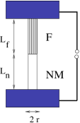
Let us consider a wire whose one end is made of a ferromagnet, the rest being a nonmagnetic metal, see Fig. 1, which is fixed rigidly to the electrodes. Ideally, the ferromagnet is uniformally spin polarized in a direction parallell to the wire. If a current is driven through it, the spin polarized electrons in the ferromagnet loose on average each an angular momentum at the interface between the two parts of the wire. Here, is the ratio of conduction electrons which flip their spin when they enter or leave the ferromagnet. We assume that the spin flip of the conduction electrons occurs in a region of length small compared to the length of the wire. Thus, a current gives rise to a rate of spin flip , and may thus produce a maximal torque along the wire of magnitude
| (1) |
where is the charge of an electron.
II Torsion Balance
The torque caused by the finite spin flip rate, Eq. ( 1 ), is in balance with the torque due to the elastic torsion of the wire, as well as a torque due to the finite inertia of the wire, and a friction torque when the torsion angle changes in time.
A torsion of the ferromagnetic wire by an angle causes a torque of magnitude [2, 6]
| (2) |
where is the shear modulus, the length of the ferromagnetic wire and its radius. We assume that the torque on the nonmagnetic wire when it is torted by the angle , is smaller than the torque in the ferromagnetic wire , so that the torsion angle is determined by , only. Note that we consider here the situation when the wires are under no tension. If there is a force on the wires, producing the tension , it has to be substituted for the shear modulus .
When the angle changes in time, there is an additional torque due to the inertia of the wire,
| (3) |
The inertia of the two wires, each fixed at one end, is
| (4) |
where the subscript denotes the values for the nonmagnetic wire, and is the mass density of the respective wire. Note that the inertia may be changed independently of the wire geometry by attaching a weight. Therefore we have included another finite contribution to the inertia.
There is also a small friction torque, which can be taken of Stokes form:
| (5) |
where is the friction constant.
Thus, in total there is a balance of torques,
| (6) |
yielding a second order differential equation for the torsion angle .
If the current is constant in time, the torsion will reach equilibrium at a finite angle
| (7) |
In order to enhance the torsion angle one can send an alternating current through the wire and bring it in resonance with the eigen frequency of torsion oscillations of the wire system. For a sinusoidal current, , there is resonance at the frequency,
| (8) |
In resonance the maximal torsion angle is limited by the friction, and there is a torsional oscillation where the amplitude is obtained from Eq. (6) as,
| (9) |
The friction constant is related to the decay rate with which a torsion oscillation decays, when there is no driving force, : .
Substitution in Eq. ( 6 ) gives . In order that resonance can be observed, the decay rate must be much smaller than the resonance frequency, .
Using Eq. ( 8 ) for the resonance frequency and Eq. ( 4 ) for the inertia, we obtain the maximal torsion angle as
| (10) |
where
| (11) |
Note, that the factor g depends on the dimensions of the wires and the additional inertia , and is on the order of .
Thus, when is obtained from a relaxation measurement, the maximum amplitude of the torsion angle in resonance, Eq. (10), is a direct measure of the polarization of the conduction electrons .
III Thermal Fluctuations
The torsion due to the spin flip rate has to be compared to thermal fluctuations of the torsion angle, , at the temperature of the wire. Using Boltzmann’s equipartition theorem, setting the elastic energy equal to , where [6]
| (12) |
we find that the torsion angle may maximally fluctuate by
| (13) |
IV Example
As an example we consider at room temperature a ferromagnetic wire made of with a Curie temperature of , a torsion modulus , and density [7]. The geometric parameter is chosen as . In the following we write the physical parameters in experimentally relevant units: the current , the radius, , the length , and the decay rate where the letters in bold face denote the dimensionless parameters. Thus, we obtain for the torsion angle Eq. ( 7 ) as a function of only dimensionless parameters:
| (14) |
In resonance the maximum torsion angle is from Eq. ( 10 )
| (15) |
with the resonance frequency
| (16) |
As an example, when a constant current of is driven through an iron wire of thickness and length , it becomes torted by the angle while a maximum torsion angle can be achieved in resonance with an oscillating current of amplitude , with a frequency of , if the system has an independently measured relaxation rate .
For the thermal torsion angle fluctuations we obtain at a temperature :
| (17) |
which gives at room temperature for the above example a fluctuation of .
To estimate the heating of the wire with respect to the environment with constant temperature , we assume that the heat current is radially emitted out of the wire. With the values for for the resistivity and the thermal conductivity , we obtain that the radial temperature gradient is
| (18) |
For the example follows a heating of , which can be neglected at room temperature.
V Conclusions
The spin flip rate at the interface between a ferromagnetic and a nonmagnetic wire results in a torsion of the wire. The magnitude of the torsion angle seems, at least in resonance, in an experimentally accessible range, and can even at room temperature exceed the thermal torsion fluctuations. The effect can be strongly enhanced and its ratio to thermal fluctuations be increased, by decreasing the wire thickness, while its dependence on temperature is relatively weak.
The torsion angle can therefore serve as a direct measure of the degree of magnetic polarization of the conduction electrons . is known to be close to in doped , since the spin- up and spin- down bands are well separated in energy in these compounds[8]. In ferromagnetic transition metals like , it is not yet known to which degree the contribute to the electric transport [9], and therefore the measurement of the degree of magnetic polarization of the conduction electrons may lead to a better understanding of that point.
S. K. thanks Mukul Laad and Mark Leadbeater for usefull discussions.
REFERENCES
- [1] O. W. Richardson, Phys. Rev. 66,248(1908).
- [2] A. Einstein, W. J. de Haas, Verhandl. Dt. Physik. Gesell. 17, 152(1915).
- [3] R. A. Beth, Phys. Rev. 50, 115(1936).
- [4] R. Doll, M. Näbauer, Phys. Rev. Lett. 7, 51(1961).
- [5] M. B. Stearns, Phys. Today 34 9, (April 1978); A. Aharoni Introduction to the Theory of Ferromagnetism ( Clarendon Press, Oxford) (1996).
- [6] R. Feynman, Lectures on Physics II, (Addison-Wesley, Reading) (1964); L. D. Landau, E. M. Lifschitz, Theory of elasticity ,( Moskau) (1953).
- [7] C. Gerthsen, H. Vogel, Physik ( Springer , Berlin ) (1997)
- [8] A. P. Ramirez, J. Phys. Cond. Matt. 9,8171 (1997).
- [9] P. Fulde, Electron Correlations in Molecules and Solids (Springer, Berlin) , 3rd edition (1995).