[
Geometrically Induced Multiple Coulomb Blockade Gaps
Abstract
We have theoretically investigated the transport properties of a ring-shaped array of small tunnel junctions, which is weakly coupled to the drain electrode. We have found that the long range interaction together with the semi-isolation of the array bring about the formation of stable standing configurations of electrons. The stable configurations break up during each transition from odd to even number of trapped electrons, leading to multiple Coulomb blockade gaps in the the characteristics of the system.
pacs:
73.23.Hk, 73.23.-b]
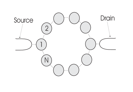
Transport properties of arrays of small tunnel junctions, such as the Coulomb blockade effect and correlated single electron tunneling, have been studied extensively.[2, 3, 4, 5, 6, 7] Most of the studies, however, were carried out for one-dimensional (1D) arrays and were based on the nearest neighbor interaction approximation.[2, 3, 4, 5] The soliton potential in that case is known to decay exponentially with the screening length where and are the junction capacitance between neighboring dots and the self-capacitance of a dot, respectively. According to recent studies, however, the soliton potential in one- or two-dimensional arrays should decay as , where is the distance, if the full interaction between dots in the array is taken into account.[6, 7] In this work, we have applied the full interaction result to a ring-shaped array as shown in Fig. 1, which has two branches or paths for electrons between the source and the drain electrodes. Due to the long range interaction between dots, the charge distribution of one branch of the array is expected to substantially affect that of the other branch, which should considerably influence the transport property of the array.
Furthermore, we have isolated the array from the drain to some degree in order to trap the electrons more easily within the array. These two ingredients, i.e., the long range interaction and the semi-isolation of the array, will be shown to lead to multiple Coulomb blockade gaps in characteristics under some conditions, which will the main topic in this paper.
In the semiclassical approach that we have adopted here,[2, 3, 4, 5] the charge of the -th dot of the system of Fig. 1, where nearest neighboring dots are coupled by a tunneling junction, is given by
| (1) |
where is the potential of the -th dot and where
| (2) | |||||
| (3) |
where is the capacitance between the -th and -th dots. We have modeled the as follows:
| (4) |
where is the distance between the neighboring dots (assumed to be the same for all neighbors) and is the real, two-dimensional distance between the -th and -th dots. The soliton potential in this full-interaction model decays as , where is the distance between dots, so as to be consistent with the recent full interaction studies.[6, 7] The parameter determines the degree of screening ability of nearby dots. The range seems to be reasonable for semiconductor arrays with poor screening.[6]
To isolate the array from the drain to some degree, the capacitance between the drain electrode and each dot in the array is further multiplied by a uniform factor . We have set in this work, at which value the array is still conducting but coupled to the drain sufficiently weakly.
The current is calculated for constant bias voltage between the source and the drain, via standard Monte Carlo simulation.[3, 5] The transition rates are determined by using the Golden-rule formula, with the electrostatic energy of the form
| (5) |
In this paper, the unit of the current, the voltage, and the temperature are , and , respectively, where is the inverse of the transmittance across the junction between neighboring dots.
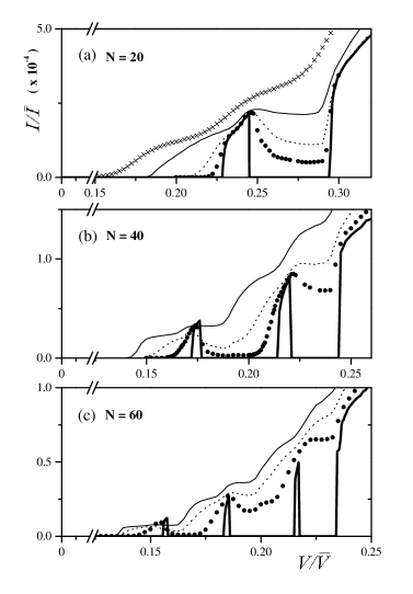
We show in Fig. 2 the characteristics of the ring-shaped array with = 20 (a), 40 (b), and 60 (c), at various temperatures. In contrast to the simply-connected 1D array case where there is only one Coulomb blockade gap in a low-bias voltage range, the zero-temperature characteristics in Fig. 2 exhibit sharp multiple gaps: there are two gaps for the array with 20-dots, three for 40-dots, and four for 60-dots. These gaps at zero temperature are transformed into negative differential conductance (NDC) regions at finite temperatures, ultimately showing monotonically increasing behavior at higher temperatures.
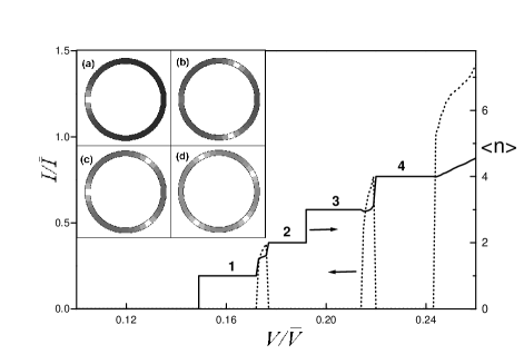
In Fig. 3, we have shown and the average number of electrons within the 40-dot array at zero temperature. shows clear steps with integer multiples up to , beyond which it increases monotonically without showing further steps, as does the current. The potential profiles at the plateaus of = 1, 2, 3, and 4 for the 40-dot array are shown in Fig. 3-(a), (b), (c), and (d), respectively. From the figure, it is clear that the current peaks arise during the transient phase in which changes from odd to even ( and for the first and second peaks) and the multiple Coulomb gaps are separated by those peaks. Likewise, the peak for the 20-dot array arises during the transition, and the peaks for the 60-dot show up during , , and transitions, respectively. The corresponding potential profiles at the plateaus are similar to the ones in Fig. 3.
The charge configurations shown in Fig. 3 for the 40-dot array are stable insulating configurations with integer number of trapped electrons within the array. As the bias voltage increases from zero, the system undergoes successive transitions from one stable configuration to another. If a transition occurs from even to odd , for instance, from to , the transition is smooth and immediate: a new electron which just tunneled into the array to make merely pushes the already built-up standing charge configuration of two electrons a bit toward the drain and the newly tunneled electron stays on dot 1, making another stable configuration of three electrons (see Fig. 3-(b) and (c)). However, when a transition occurs from odd to even , for instance from to , the transition takes place via intermediate unstable states. As the bias voltage increases such that tunneling of the second electron into dot 1 from the source is inevitable, the electron which has been on dot 1 is pushed and moves toward the drain. Then possible charge configurations are: either one electron solely travels toward the drain before another tunnels into the array, or one electron in one branch travels ahead of the other electron in the other branch. While these unbalanced charge configurations persist, the system becomes conducting, until the stable configuration of two electrons as shown in Fig. 3-(b) is eventually established at a higher bias voltage. That is why the current peaks show up during the transient phase from odd to even number of , whereas no current peaks arise during the transition from even to odd .
We may draw an analogy for the behavior of the ring-type array to melting of a solid. The state when the standing configuration is built up may be compared to a rigid solid state with symmetry. When the externally-driven distortion of the lattice exceeds some threshold, the symmetry is broken and the solid starts to melt. Likewise, the bias voltage in our array drives the system toward broken-symmetry state (the transient state during which changes from odd to even) and the array becomes conducting. In this case, the symmetry is imposed by the special geometry which has two branches. One difference in this analogy is that the array system becomes insulating again when the symmetry of the system is restored with higher integer value of .
The instability of the transient region (from odd to even ) is increased by the thermal fluctuations, so its width broadens as the temperature is raised. Therefore, the current peaks, whose widths depend on that of corresponding transient regions, also broaden at higher temperatures, as can be seen in Fig. 2. The thermal fluctuations also destabilize the standing configurations themselves established at zero temperature. The thermal fluctuation gives the trapped electrons making up the stable configurations a small but finite probability to tunnel through nearby junctions. Once such tunneling event takes place, the balanced configuration is temporarily broken and a trapped electron exits through the drain, and the non-zero current flows in the additional Coulomb blockade region, resulting in NDC behavior in the curve.
We can estimate the degree of stability of a charge configuration by calculating the free energy changes for its transitions to adjacent configurations. For each of the stable configurations discussed above, for all possible transitions to adjacent configurations: that is, they are local minima of the free energy in the configuration space. To illustrate this point, let us consider the simplest possible case of the 4-dot array with identical junctions, where the stable configuration responsible for the second Coulomb gap is (i.e., when electrons are at the second and the fourth dots - see Fig. 1 for the dot indices). If we calculate the free energy change for transitions to adjacent configurations and , we have (for the case of strong screening, for simplicity)
| (6) | |||||
| (7) |
where the first term represents the electrostatic energy change, the second the work done by the voltage source, and . Eq. (6) shows that if and if , . Thus, the configuration with electrons at dots 2 and 4 is locally stable, unless thermal fluctuations which overcome the free energy difference are introduced, that is, if . Further analysis with free energy changes can also give the widths of the multiple Coulomb gaps and peaks. For the 4-dot case, the second Coulomb gap appears in the interval of (), where and are the threshold voltages for entrance of the second and the third electron into the array, respectively, which are given by and , where . Further details will be published elsewhere.
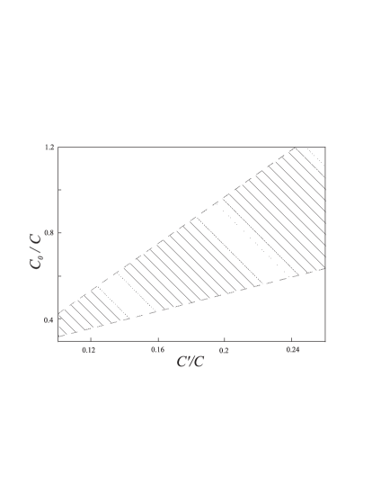
As can be seen in the above analysis, is an important factor for existence of the multiple Coulomb gaps in the characteristics. To observe the multiple Coulomb gaps separated by peaks, should not be too weak nor too strong: in the intermediate range of the multiple Coulomb gaps are seen in general. The range is, however, dependent on another factor which reflects the degree of screening by nearby dots. In Fig. 4, we have schematically drawn the region, in the plane of and , where the multiple Coulomb gaps appear for the 20-dot array at zero temperature. As one may anticipate, the figure shows that with less screening, which implies stronger interaction among dots, the shaded region becomes wider as it shifts toward weaker coupling between dots. At finite temperatures, the shaded region expands considerably because the thermal fluctuations can give rise to appearance of peaks which were too narrow to be seen at zero temperature.
The heights of the current peaks are multiples of the first peak height. In Fig. 2-(b), the ratio of the first and the second peak heights for the 40-dot array is very close to 1:2. That is because the current peaks at zero temperature reach their maxima just before the standing configurations composed of even number of electrons are built up, as Fig. 3 clearly shows. Likewise, for the 60-dot array, the ratio of the current peak heights are close to 1:2:3.
The multiple Coulomb gaps are observed only when the standing configurations through interaction between equal number of electrons in upper and lower branches of the array are built up. For arrays of large size (), the standing configurations as shown in Fig. 3 are possible due to the long-range nature of the interaction (Coulomb repulsion). For arrays of smaller size (), even nearest neighbor interaction with exponentially decaying soliton potential is sufficient to bring about the standing configurations. However, due to the small array size, only one additional gap is seen in this case and, in contrast to the case of the 20-dot array of Fig. 2-(a) where the second gap appears when , the second gap in arrays with the nearest neighbor approximation appears with higher , which means that, due to the short-range interaction, more electrons are needed to build up the standing configuration. Likewise, if the condition of weak coupling of the ring-type array to the drain is lifted (i.e., = 1), it becomes harder for the electrons to be trapped inside the array such that, as in the case of nearest neighbor interaction only, the standing configurations appear with higher than in arrays with weak coupling to the drain.
The multiple Coulomb gaps are quite robust against possible imperfection of the array. In real experiments, one can hardly expect the dots in the array to be identical nor the array itself to be perfectly symmetrical. The effect of those imperfections may be reflected in our simulation simply by allowing the mutual capacitances given by Eq. (4) to have ‘random’ contributions to some degree. That is, , where is a constant adjusting the magnitude of the randomness and ’s are random numbers between -1/2 and 1/2. Note that we have specifically put the subscripts for to note that the random numbers are differently assigned for different dots and different pairs of dots. We have observed that for up to for the 20-dot array, the multiple Coulomb gaps are still seen (with peak positions a bit shifted) or, at least, NDC regions are seen in place of the multiple Coulomb gaps. If the source and the drain electrodes are asymmetrically attached to the array, the multiple Coulomb gaps or the NDC regions are seen as well. The stable charge configurations when those disorders are introduced are similar to the ones in Fig. 3 but with trapped electrons residing on geometrically asymmetrical points as a consequence of their adjustment to changes in electrostatic forces due to imperfections in the array. That the multiple Coulomb gaps are robust against such perturbations implies that details in modeling of the mutual capacitance matrix are not important as long as the long range Coulomb forces between dots are included.
We have also investigated the possibility of observing the multiple-gap behavior in arrays with two branches whose geometrical shape departs from the circular one that we have considered here. Our tentative conclusion is that the multiple Coulomb blockade gaps and NDC behaviors seem to be generic features of arrays with two branches, although the systematic behavior of with change of is better seen in the system that we have considered in this paper. In the discussion of the multiple gaps and the current peaks between them, the essential point was that it is possible that, between two stable insulating states, there is an unstable conducting state that the system has to go through, and the unstable state is brought upon by the topology of the configuration (two branches). Whether the geometry of the array is circular or elliptical should not matter, as long as stable configurations with different number of trapped electrons are found in the array. One may also note that the multiple Coulomb gap phenomena is not possible in one-dimensional arrays with simply-connected geometry. In real experiments, where the size of the dots in the array should have some distribution about the average value and the temperature is low yet finite, we predict that it is mostly likely that the negative differential conductance regions can be seen in the curve in place of the additional Coulomb gaps.
This work has been supported by the Ministry of Information and Communications of Korea.
REFERENCES
- [1] E-Mail: mcshin@etri.re.kr
- [2] Among others, K. K. Likharev, IBM J. Res. Dev. 32, 144 (1988); G. L. Ingold and Yu. V. Nazarov, in Single Electron Tunneling, edited by H. Grabert and M. H. Devoret (Plenum, New York, 1991), p. 21; P. Delsing, ibid, p. 249.
- [3] M. Amman, E. Ben-Jacob and K. Mullen, Phys. Lett. A 142, 431 (1989).
- [4] G. Y. Hu and R. F. O’Connell, Phys. Rev. B 49, 16773 (1994).
- [5] N. S. Bakhvalov, G. S. Kazacha, K. K. Likharev and S. I. Serdyukova, Zh. Eksp. Teor. Fiz. 95, 1010 (1989) [Sov. Phys. JETP 68, 581 (1989)].
- [6] C. B. Whan, J. White and T. P. Orlando, Appl. Phys. Lett. 68, 2996, (1996).
- [7] K. K. Likharev and K. A. Matsuoka, Appl. Phys. Lett. 67, 3037 (1995 ).