Simulations of energetic beam deposition: from picoseconds to seconds
Abstract
We present a new method for simulating crystal growth by energetic beam deposition. The method combines a Kinetic Monte–Carlo simulation for the thermal surface diffusion with a small scale molecular dynamics simulation of every single deposition event. We have implemented the method using the effective medium theory as a model potential for the atomic interactions, and present simulations for Ag/Ag(111) and Pt/Pt(111) for incoming energies up to 35 eV. The method is capable of following the growth of several monolayers at realistic growth rates of 1 monolayer per second, correctly accounting for both energy–induced atomic mobility and thermal surface diffusion. We find that the energy influences island and step densities and can induce layer–by–layer growth. We find an optimal energy for layer–by–layer growth (25 eV for Ag), which correlates with where the net impact-induced downward interlayer transport is at a maximum. A high step density is needed for energy induced layer–by–layer growth, hence the effect dies away at increased temperatures, where thermal surface diffusion reduces the step density. As part of the development of the method, we present molecular dynamics simulations of single atom–surface collisions on flat parts of the surface and near straight steps, we identify microscopic mechanisms by which the energy influences the growth, and we discuss the nature of the energy–induced atomic mobility.
pacs:
PACS numbers: 81.15.Jj, 68.55.-a, 61.72.CcI Introduction
The overall goal of being able to manufacture nanoscale devices while controlling chemical composition and crystal structure has been the driving force behind a tremendous effort in numerous research groups over the past decades, and the ability to grow crystal surfaces in a layer-by-layer fashion has been a key issue [1]. The use of energetic particles has offered a promising possibility of gaining control of the growth process [2, 3].
There are numerous examples where energetic beams have been used to control and improve the properties of the grown materials. Ion Beam Assisted Deposition [4], Ion Beam Sputter Deposition [5] and Ion Beam Direct Deposition [6, 7], have been used to lower the epitaxial growth temperature and improve smoothness. Increased control of interfacial roughness has been achieved through sputter deposition [8], and Giant Magnetoresistance has been improved both using both sputter deposition [9, 10] and using direct ion beam deposition [11].
Not surprisingly, there can be an optimal window for the energy per incoming particle: a certain energy is needed to increase atomic mobility at the surface, but too high an energy can cause a drastic increase in defect formation. There is a growing literature on experiments which map out parameter space to find optimal values for various systems, and the optimal energy window is often found at relatively low energies. For example, Rabalais et al. found that for silicon ion–beam epitaxy very smooth growth was obtained using 20 eV particles [7].
There is an obvious need for improving our understanding of how the energy influences the growth. What are the microscopic mechanisms by which the energy changes the growth morphology? Recent experiments have illustrated how the energetic ion–surface collisions can influence submonolayer island densities during growth of a Pt(111) surface by sputter deposition [12, 13] or Ion Beam assisted deposition [14]. Several experimental groups are operating [6, 7] or building equipment for Ion Beam Direct Deposition with high control of beam energy and angle of incidence [15], and we can expect much more detailed experimental information on the effect of the energy in the near future.
Molecular dynamics (MD) simulations using model potentials, from which very detailed information on microscopic mechanisms can be obtained, have proven to be a very useful tool in studying energetic ion–surface [16, 17, 18, 19, 20, 21] and cluster–surface [22] collisions. There are several questions that can be directly addressed using MD. What kind of atomic rearrangements occur in the ion–surface collisions as a function of energy? Is ballistic motion or local heating the right picture of the energy–induced mobility? What are the time and length scales of the induced mobility? For example, Villarba and Jonsson [16] studied low energy (10 and 20 eV) impact of Pt atoms on a Pt(111) surface, and identified push–out events where atoms impinging close to descending steps are incorporated into the growing layer. The net effect is that the step edge grows horizontally favoring a layer-by-layer growth mode. They found that the non-thermal effect of the collision was over in a few picoseconds, and the ranges of the collision–induced atomic rearrangements were a few lattice sites.
One issue, which MD fails to address, and which is crucial in understanding most experiments using energetic particles, is what is the relative importance of collision–induced atomic mobility on the one hand, and the thermal surface diffusion on the other? MD simulations attempting to simulate the entire growth process must use deposition rates on the order of monolayers per sec (ML/s) [18, 19, 20], and neglect the effect thermal surface diffusion on longer time–scales. Furthermore, subsequent collision events might affect each other directly in ways they would not at the much lower experimental deposition rates (typically 0.01 - 1 ML/s). If we want to address this question of the relative importance of collision–induced mobility and the thermal surface diffusion, we are faced with a tremendous problem of time–scales. Each atom–surface collision is a pico–second event, to resolve which you need femto–second numerical time steps. At the other extreme, in the typical experimental situation there is one such collision per lattice site per 1 to 100 seconds.
In this paper we present results of a new simulation method capable of overcoming this 15 orders of magnitude gap in time–scales. We have combined two well known simulation techniques in a new way. We do a traditional Kinetic Monte–Carlo (KMC) simulation of the thermal surface diffusion in between the rare collisions, and for each of these collisions we do a small length–scale, short time–scale molecular dynamics simulation. We call this a hybrid Kinetic Monte–Carlo Molecular Dynamics (KMC–MD) simulation. We will show the results of depositing several monolayers at 1ML/sec, while treating every collision explicitly in MD simulations. As model systems, we have chosen Ag(111) and Pt(111) homoepitaxy, and we use Effective Medium Theory (EMT) [23] as a model potential. An idea similar to KMC–MD has been used to simulate damage production in ion implantation of silicon [24].
We use effective medium theory, which is known to give a good qualitative and to some extent quantitative description of these metals [23, 27]. We do not expect these simulations to accurately predict all features of the growth by energetic beam deposition of Ag(111) and Pt(111) [27]. However, we do hope to gain useful insight into how the use of energetic particles can influence growth, microscopic mechanisms, energy–induced atomic mobility, and the interplay between the energy–induced mobility and thermal surface diffusion.
The paper is organized as follows: In section II, we describe the KMC–MD method in detail, going through how the KMC part of the simulation is done (section II A), how the MD part is done (section II C), how to go from the discrete KMC to the continuous MD simulation (section II B), and back (section II D). The results section, part III, is divided into two main parts – MD simulations of single energetic atom–surface collisions (section III A) and KMC–MD simulations of the entire growth process (section III B). In section III A we start our discussion of the choice of MD system size (section III A 1), where we show that large MD systems and Langevin damping on the boundaries are essential to avoid unphysical reflections of the supersonic shock-wave induced by the impact. We then go through some important energy induced microscopic mechanisms we find for AgAg(111) and PtPt(111) energetic impacts, focusing on the energy-induced upward and downward interlayer mobility at straight step edges. We round up giving a short summary and discussion of these mechanisms in section III A 8. In section III B, we present our KMC–MD results for the submonolayer structure and for the surface roughness after the deposition of a few atomic layers; first for Ag/Ag(111) and then for Pt/Pt(111). We find the smoothest growth when both the net downward interlayer mobility and the step edge density are large. In section IV we give a concluding discussion of our results for simulations of growth by energetic beam deposition, and in section V we give a general discussion of the KMC–MD method.
II The KMC–MD Method
In the introduction above, we stated that a main difficulty in simulating crystal growth by energetic depositions is the tremendous gap in time scales between the picosecond collisions and the deposition, typically slower than one impact per lattice site per second. The idea behind the KMC–MD method is precisely that the depositions are rare events. For most of the time during the crystal growth, there is no non–thermal atomic mobility on the surface. Only the thermal diffusion of atoms is active. Kinetic Monte–Carlo is a very efficient way of evolving the surface for this time in between the energetic collisions, given a model of the thermal diffusion.
Once in a great while (on the time scale of diffusion) an energetic collision occurs. These collisions may displace the incoming atom from the impact site, as well as rearrange the surface atoms. But for homoepitaxial metal systems, the energy transfer is very efficient, and the incoming atom generally slows down very quickly. Also, in the crystalline environment, the excess energy dissipates away very quickly due to phonons. Consequently, non-thermal mobility is limited to a very short time, , after the collision. Furthermore, for not too high incoming energies, the collision–induced mobility is fairly short ranged. This makes MD of the collisions a suitable method.
In the KMC–MD method, we evolve time using a KMC simulation in a standard way [28, 25, 29, 26]. Diffusion processes happen sequentially according to their relative rates and, with a probability proportional to the deposition rate, new atoms are introduced above the surface with a specified kinetic energy and angle and aimed at a random point on the surface. When this happens, we set up an MD simulation to correctly describe the atom–surface collision. We include only the local region in the vicinity of the impact site in the MD simulation, and run for only a short time. We then feed the end result back into the KMC simulation, and continue. In sections II A-D below, we describe the details of the different parts of the KMC–MD method.
We model the atomic interactions using effective medium theory [23] — in the MD simulations of the energetic collisions we use the EMT forces, and in the KMC–simulations we use a comprehensive set of EMT energy barriers for various atomic diffusion processes.
A The KMC lattice simulation
Kinetic Monte–Carlo has become a standard method for doing lattice simulations of crystal growth [28, 25, 29, 26]. In short, we make a complete table of the active atomic diffusion processes at the given temperature. For each type of diffusion process we evaluate its rate as , where we assume a common prefactor of for simplicity. Table I lists the processes we include together with their EMT energy barriers for the two systems (Ag/Ag(111) and Pt/Pt(111)). The surface atomic configuration is specified by the occupancy by atoms of the fcc(111) lattice sites. For every atom on the surface we examine if it can potentially make a lattice jump in any of the processes from table I, and if so we add these specific atomic jumps, and their rate to a list of all the possible potential diffusion processes the given surface configuration can evolve by. Also included in the list is the deposition of a new atom — with a rate given by the deposition flux times the surface area. Now, in every loop of the program, with a probability proportional to its rate, one particular atomic jump is chosen from the list of potential processes. The surface configuration and the list of potential processes is then updated accordingly, taking advantage of the fact that there will be only local changes. Because there is a lattice jump or a new deposition in every loop of the program, KMC is a very efficient method, and can bridge one gap of time–scales: the gap between fast thermal diffusion processes ( to per sec.) and the deposition rate. We depart from the standard way of doing crystal growth with KMC in the way we handle deposition events. Usually in KMC simulations when a deposition event is chosen to happen, a new atom is introduced at a random surface lattice site. Instead we do something new — a complete MD simulation of the atom–surface collision with the specified energy and angle and an impact parameter for the incoming atom chosen at random.
In simulations of thermal crystal growth and relaxation the KMC method has been used in two ways: the energy barriers giving the rates can be obtained from a model potential energy, or they can be used as adjustable parameters to fit growth experiments or to study the effect of a particular process on the resulting surface morphology. In our case, to make the two parts of the simulation consistent with one another, the KMC energy barriers must be obtained from the potential energy used in the MD simulations.
B From discrete KMC to continuous MD
When the KMC algorithm chooses a deposition event, a random point in a plane above the surface is picked. From this point, a straight line at the ion beam angle is then followed until it crosses a horizontal (111)–plane near (within a surface unit cell of) a lattice site occupied by an atom, which we will call the impact atom. With respect to this expected impact atom, the cluster is set up based on the occupancy of sites in the KMC–simulation, as discussed below.
| Metal | Ag | Pt | |||
|---|---|---|---|---|---|
| Terrace diffusion | |||||
| Diffusion of monomers | 67 | 158 | |||
| Diffusion away from descending steps | — | 208 | |||
| Diffusion of dimers | 132 | 220 | |||
| Diffusion of vacancies | 540 | 690 | |||
| Detachment | |||||
| Dissociation from 1 neighbor | 315 | 500 | |||
| Edge diffusion | |||||
| Corner diffusion | 1 | A | 1 | 77 | 220 |
| Corner diffusion | 1 | B | 1 | 132 | 130 |
| Step to corner | 2 | A | 1 | 257 | 510 |
| Step to corner | 2 | B | 1 | 317 | 410 |
| Step Diffusion | 2 | A | 1 | 221 | 450 |
| Step Diffusion | 2 | B | 1 | 296 | 390 |
| Kink to corner | 3 | A | 1 | 423 | 740 |
| Kink to corner | 3 | B | 1 | 478 | 650 |
| Kink to step | 3 | A | 1 | 387 | 680 |
| Kink to step | 3 | B | 1 | 457 | 630 |
| Inter–layer diffusion | |||||
| Descent at straight step | 240 | 400 | |||
| Descent next to kink at B-step | — | 270 |
Before introducing the energetic atom, the system is equilibrated at the specified temperature. We find that an efficient way to do this is to give every atom a velocity picked from a Maxwell–Boltzmann distribution corresponding to twice the temperature. Since the atoms start out on perfect lattice sites, this gets the total energy per atom roughly right. We then need only to run for 0.27 ps to get a reasonably equilibrated system. Finally, the atom is placed three horizontal (111) planes upward along the straight line introduced above, and is started with the specified kinetic energy.
C The MD continuous simulations
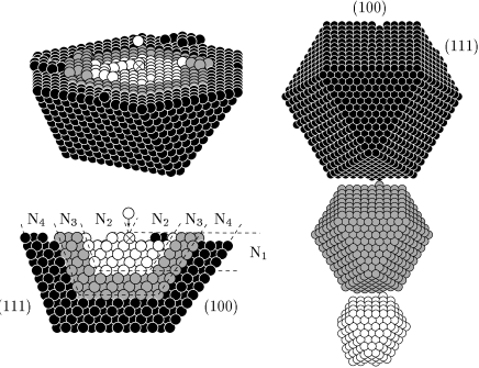
Following DePristo and Metiu [31] we set up a cluster consisting of three types of atoms. The atoms in the immediate vicinity of the impact site evolve classically according to the EMT forces only (we call these MD–atoms). Surrounding the MD–atoms we have a shell of Langevin atoms, which are subject to the EMT forces, and in addition to a friction force and a randomly fluctuating force. To fix the geometry a shell of static atoms surrounds the shell of Langevin atoms (Figure 1). The equations of motion for the dynamic atoms are:
| (1) |
where and are the three Cartesian coordinates and the mass of atom , is the EMT potential energy as a function of all atomic coordinates , is the Langevin friction coefficient of the atom (the use of the index will be modified below), is time and is the fluctuating force obeying the fluctuation–dissipation theorem:
| (2) |
The central MD–atoms have zero friction coefficient, . We integrate equation 1 in time using the algorithm proposed by Allen and Tildesley [32], which reduces to the Verlet algorithm for .
Having a shell of Langevin atoms which surrounds the MD–atoms serves several purposes. It allows us to equilibrate the system at a specified temperature before shooting in the energetic atom; it mimics the contact of the MD–atoms with an infinite heat bath (the crystal), ensuring that the deposited energy doesn’t permanently heat up the system; and furthermore, as we shall see later, it allows us to use a smaller system size without unphysical reflections of energy from the boundaries affecting the atomic motion near the impact site. We will return to a discussion of this latter point in section III A. We always use and , except for a test calculation with no Langevin atoms (). Having 3 atomic planes of Langevin atoms, we use the possibility of having different Langevin coefficients for each plane. We label these coefficients , where is for the plane neighboring the MD–atoms, and is for the plane neighboring the static atoms (fig. 1).
Apart from how the cluster boundaries affect the energy dissipation away from the impact site, another criterion for choosing the size of a cluster simulation is the range of the transient mobility induced by the collisions. In the energetic collisions, atoms are usually displaced a few lattice sites from the point of impact, and it is important that these atoms stay in contact with the region of MD–atoms. Occasionally, incoming atoms do not stick to the surface, but are reflected back. For rare impact parameters on step edges, incoming atoms may travel rather long distances along the surface before sticking and thermalizing. In long simulations with thousands of depositions such events will be encountered. However, at the end of an MD simulation where the lattice sites of the atoms have to be identified, we check if any dynamic atoms left the physical region of the cluster calculation. Our KMC–MD system sizes were sufficiently large that this happened in fewer than 2% of the deposition events.
Every MD simulation is followed for 5 ps. After this time, the average kinetic energy per atom in the local impact region is once again , and all further atomic mobility will be thermally activated and well–described by the KMC lattice simulation.
We find it important to use a variable time step in the MD simulations of the collisions. However, based on Figures 2 and 3, we choose to do this in the simplest possible way. The very high kinetic energies are all found within the first 0.5 ps of the collisions, and after this time the atoms have much more moderate velocities. We use the Verlet algorithm, with a time step of fs for the first 0.5 ps, and subsequently we use fs for the remaining 4.5 ps. By comparing to much shorter time steps, we have checked that this scheme, for energies up to 30 eV, is sufficient to correctly identify the lattice sites of all atoms after 5 ps, whereas using for the entire collision would give inaccurate results.
D From continuous MD to discrete KMC
After having the done the MD simulation for the local vicinity of the impact, when all atomic mobility is once again thermal, we need to map the end result of the continuous simulation back to the lattice description of the KMC part of the simulation. In the thermal surface configuration every atom is oscillating around a local minimum of the EMT potential energy surface. To identify the binding site of each atom, we simply minimize the energy with respect to the atomic coordinates. This uniquely identifies an fcc lattice site for almost all the atoms.
However, there is one exception to this. The presence of hcp binding sites on the fcc(111) surface give rise to off–lattice local energy minima which can trap atoms. In EMT, an isolated adatom at the surface has essentially the same energy when at an fcc and an hcp site, and has roughly equal probabilities of occupying the two types of sites. As a result, during growth islands can nucleate on hcp sites as well as fcc sites, which would possibly make the coalescence of each new layer a very complicated process involving surface dislocations separating regions of hcp and fcc stacking sequences. However, low temperature growth experiments for Ag/Ag(111) and Pt/Pt(111) do not show the complicated behavior expected if islands of substantial size had significant probabilities of being on hcp sites — for Ag/Ag(111) the growth is known to proceed on the fcc sites [33]. More accurate total energy calculations for Pt/Pt(111) [34] finds a significantly increased energy for the adatom at the hcp site, suggesting that the strong binding at hcp sites is an artifact of the effective medium theory, due to the lack of dependence of the energy on relative bond angles. For these reasons, and because it would make the KMC simulation infeasible, we do not allow atoms to occupy hcp sites.
Since the hcp sites are unfavorable, and thermal diffusion will rapidly shift atoms from hcp metastable sites to neighboring fcc sites, we need a procedure which takes the atoms on hcp sites in the energy minimized configuration, and puts them on one of the three neighboring fcc sites. When doing this the important thing is not to break any bonds if, for example, a dimer on hcp sites has to be displaced. For each atom that ended up on an hcp site after the energy minimization, we move it to the neighboring vacant fcc site of highest in–layer coordination, or a random choice among these sites if there are several equivalent ones.
With all atoms occupying fcc sites, we can continue the KMC simulation of the thermal surface diffusion.
III Results
We present the results of our simulations in two subsections. Before showing the results for the growth simulations with the KMC–MD method in section III B, we present and discuss MD simulations of single atom–surface collisions in section III A below. We start out discussing the choice of system size in the MD simulations, and how for small systems this affects the outcomes of the collisions. We then move on to classify and quantify the collision–induced processes influencing atomic mobility found at relatively low energies () for AgAg(111) and PtPt(111). Unless otherwise specified, the collisions occur at normal incidence and with random impact parameters.
A MD of single atom–surface collisions
1 Choice of MD system size: avoiding reflected energy from the boundaries
In atom–surface collisions, the deposited energy is dissipated away from the local impact region by shock–waves and phonons. Clearly, how much energy stays around for how long a time is crucial for how much atomic mobility the collision causes. When doing a cluster simulation of the collision, it is possible that the finite system size will affect the energy density in the impact region after the collision — outgoing energy waves will be reflected at the boundaries and come back to the local impact region. This is illustrated in figure 2, which shows results for 25 eV AgAg(111) impacts for a system setup given by and Langevin coefficients . The lower panel in the figure shows the kinetic energy averaged over many impacts for individual atoms near the impact site as a function of time. For the first 0.4 ps, this graph is indistinguishable from the corresponding graph for a much bigger system. At 0.4 ps, we see that the second–layer atoms (#3) suddenly accelerate, and immediately after that the impact atom in the first layer (#2) gets a boost of kinetic energy. This sudden acceleration after 0.4 ps is absent in a calculation for a sufficiently big system, and is due to energy reflected by the static atoms at the boundaries of the cluster. The upper panel in the same figure shows the height of the impact atom above the first surface–layer as a function of time, for thirteen individual impacts. We see that this atom sometimes stays in the same layer, sometimes pops out of the surface layer and equilibrates as an adatom, and once ends up one atomic layer down. The fact that the impact atom can pop out is an energy–induced effect. It does not happen for thermal impacts. However, the figure illustrates that for system sizes this small, the impact atom gets a sizeable boost of energy reflected from the boundaries right at the critical time: just where some trajectories take the atom out of the surface layer and some don’t. And, as we shall see shortly, the probability of surface atoms popping out in the energetic impacts depends on the system size for small clusters.


Figure 3 shows the kinetic energy of the 11 atoms neighboring the impact site (average of the 11 curves in the lower panel of figure 2), again averaged over many impacts, and now for four different system sizes and Langevin coefficients. This plot shows a bump in the local kinetic energy around 0.5 ps after the impact, and that the size of this bump depends on the system size and on the Langevin coefficients of the boundary atoms. The small system setup is the same as in figure 2 and has a total of 757 dynamic atoms (MD–atoms + Langevin atoms), and both have 1093 dynamic atoms (for some of these are Langevin atoms), and has 2741 dynamic atoms. As noted above, curves for smaller systems can deviate from those for bigger system sizes because of reflections from the boundary. That the curve for deviates significantly from after 0.36 ps, whereas and deviate from only after 0.45 ps, reflects the fact that that the bigger the system the later the traveling reflected energy wave will affect the local impact region. We believe that the bump in the curve for will not disappear as the system size is increased further; extrapolating from the times at which the curves for , , and deviate from , we estimate that the reflected energy for does not return until after roughly 0.5 ps, at which time this bump has already reached its peak. The size of the bump is reduced from to by increasing the system size. It is then reduced further from to merely by tuning the Langevin coefficients on the boundary atoms. We have done an extensive numerical exploration to find the optimal choice of Langevin coefficients, and found , , and to be a good choice. A Langevin coefficient too high and too close to the impact region will cause energy reflection at early times directly from these Langevin atoms. The value seems to be the optimum for the outer most layer of Langevin atoms. We have also tried random Langevin coefficients within each layer, to avoid focusing of the reflected energy, but without finding improvements. It is evident that the curve for is not completely converged: the local kinetic energy is affected by the boundaries for the system . However, we shall argue below that it is sufficiently converged that it does not significantly affect the atomic rearrangements in which we are interested.
We note that the time at which the reflected energy comes back tells us that the energy wave travels at a supersonic speed. This is due to anharmonicities in the potential energy at the relatively large atomic displacements: the atomic collisions at the earliest times are presumably exploring the hard core of the potential and hence can propagate faster than harmonic sound waves. Potential energy anharmonicities (e.g., backscattering from hard collisions) can also cause reflection of outgoing energy even from the MD–atoms following the true dynamics. We believe these anharmonicities cause the bump in local kinetic energy found around 0.5 ps in figure 3 for the largest system (curve ).
2 Adatom/vacancy formation
Figure 4 shows possible atomic rearrangements that result from 35 eV Ag Ag(111) impacts on an initially flat surface. In one case (first column from left), there is an exchange process, in which the incoming atom gets incorporated into the surface layer, and a surface atom pops out. The impact has no net effect on the substrate. The only net effect of the incoming energy is that the resulting adatom ends up a couple of atomic spacings away from the impact site. It is an example of energy–induced short ranged horizontal mobility, which is very common for these low energy impacts. In the second column from the left, something more happens. The incoming atom gets incorporated into the surface, but two surface atoms pop out. Compared to a thermal deposition, which would result in one adatom on the surface, the energetic impact causes the formation of an additional adatom/vacancy pair. This can potentially have a significant influence on the subsequent growth. Since these two adatoms are created very close to each other, they have a large likelihood of meeting and forming a dimer. We shall return to this point in section III B. Figure 4 also shows an example in which two surface vacancies are formed, and a total of three atoms end up outside the surface layer. Two of these atoms have met to form a dimer during the collision process.
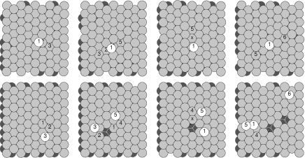
Before we turn to a discussion of the probability of making these adatom/vacancy pairs as a function of the incoming energy, let us look into the mechanism by which they are formed. Figure 5 shows the atomic trajectories for the impact shown in figure 4 column 2, in a vertical cut. This process is the most frequent way of forming adatom/vacancy pairs at 25 and 35 eV. We see atom 1 coming in, squeezing atoms 2 and 4 down and apart. After bouncing off the atoms in the second surface layer, the atoms 2 and 4 push atoms 3 and 5 out of the surface. Atom 1 takes the place initially occupied by atom 4. The picture that emerges is very ballistic. A collision sequence and ballistic reflection from the deeper lying atoms cause surface atoms to pop out.


Figure 6 shows the average number of adatom/vacancy pairs formed due to energetic AgAg(111) impacts, as a function of energy, and for the three system setups , and discussed above. The production of adatom/vacancy pairs is too high in the relatively small system with no Langevin atoms , and we have discussed above how this is due to energy reflected from the system boundaries coming back to the local impact region. However, by introducing the shell of Langevin atoms as in system , we find an adatom/vacancy production which agrees within the error bars with that of the significantly bigger system . Based on this, unless otherwise stated, in the following we use systems at least as large as , i.e., , with Langevin coefficients . and can be increased at higher energies.
Figure 6 shows a significant production of adatom/vacancy pairs for AgAg(111) impacts with incoming energies greater than 20 eV. We shall see how this will influence the growth of the surface in section III B. We have tested how this adatom/vacancy production changes when we change the angle of incidence of the energetic beam. For 20 eV and 25 eV Ag/Ag(111) impacts, at an angle 30 degree off normal incidence, we find average adatom–vacancy productions per impact of and , respectively. This calculation was done in a large cell with ,. Thus, at this angle, the adatom/vacancy production is essentially the same as that for normal incidence.
3 Atom insertion
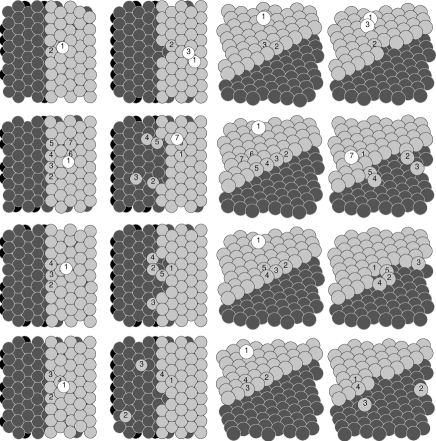
We now proceed to examine the kind of energy–induced atomic rearrangements found for impacts near straight steps on the surface. We find it important to look at possible outcomes of these single impacts in order to identify and categorize the energy–induced atomic processes influencing the growth. On the other hand, it will soon become evident that it is not feasible to quantitatively describe all possible outcomes of impacts on all possible atomic configurations of the surface. To see how energetic impacts may influence the total interlayer mobility during the growth we look at impacts in the vicinity of one of the two possible straight steps on the fcc(111) surface: the so–called B-step exposing a (111) micro facet at the step edge.
Figure 7 shows a selection of possible outcomes of 25 eV AgAg(111) impacts just above a straight B-step. The first row shows the production of an adatom/vacancy pair, equivalent to what can take place on the flat surface, as discussed above. In this particular case the two resulting adatoms on the upper terrace have met to form a dimer in the first few picoseconds after the impact. The second row shows an example of no net interlayer mobility due to the impact. The incoming atom gets incorporated into the upper terrace, but another atom (labeled 7) pops up. However, the impact does change the step structure, which is no longer straight. The collision has produced kinks on the step, and the atom labeled 3 ends up detached from the step. This can influence the growth, because it might change the subsequent thermal diffusion. For example, the thermal interlayer mobility might be different at steps with kinks [25].
Figure 7 rows 3 and 4 show examples of an energy–induced net downward interlayer mobility. Where for thermal impacts the incoming atom would stay on top of the upper terrace, it now gets inserted into the upper terrace due to the energy. This kind of process has previously been seen in molecular dynamics simulations of PtPt(111) impacts at similar energies [16]. Imagine the step is surrounding an island on the surface. The effect of the energy in this case is to change vertical growth of the island to horizontal growth at its periphery, and hence this insertion process will favor smooth growth of the surface. The examples show that the insertion process also causes a change of the step structure, and possibly detachment of atoms from the step to the lower terrace.
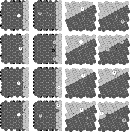
4 Atom pile–up
Figure 8 shows examples of possible outcomes of 25 eV AgAg(111) impacts just below a straight B-step. The first row shows an impact which results in an exchange process involving two surface atoms and no net interlayer mobility. The only net effect of the energy is a short ranged horizontal displacement of the adatom from the impact site, as we have seen also happens for impacts on flat parts of the surface. The second row shows an example of an adatom/vacancy formation on the lower terrace. This process is the same as the one for which the atomic trajectories are shown in figure 5, only here the two adatoms can attach to the ascending step.
Figure 8 rows 3 and 4 show examples of an energy induced net upward interlayer mobility. The atomic trajectories for the process in row 3 are very similar to those for row 1, only now atom 3 pops up in the step edge, and the step atom 4 gets piled up on the upper terrace. If the step is surrounding an island, this pile–up process causes vertical growth of the island, and hence it favors a rougher growth.

5 Dependence on energy and step position
Let us now turn to a quantitative discussion of the probabilities of the various interlayer processes we have seen can happen for impacts near straight steps. Again we look at impacts near the straight B–step, and emphasize that this is merely one example of many surface configurations an incoming energetic atom can encounter. Figure 9 shows the average net number of atoms per impact moved up or down by adatom/vacancy formation, insertion, or pile–up as a function of the distance to the step, and for 4 different incoming energies in the case of AgAg(111). At 11 eV the only significant energy–induced process is the insertion mechanism. For impacts between the first and the second row of atoms in the upper terrace, there is roughly a 50% chance of having an insertion event, hence there is a downward mobility of roughly 0.5 atom per impact. For impacts between the second and the third row of atoms, this probability has decreased to approximately 10% . There is a few percent chance of insertion events for impacts between the third and the fourth atomic row in the upper terrace. Pile–ups are defined to be when an adatom ends up on the upper terrace for impacts outside the crystal atomic position of the step atoms, i.e., for “distance to step” greater than zero. At 11 eV we see that there is a few percent chance of pile–ups for impacts within one atomic row width from the step. We note that with this definition, it is possible that there would be a few pile–ups even thermally for impacts very close to the step edge.
At 18 eV, the picture is more or less as at 11 eV, except that there is an increased probability for the insertion events, in particular for impacts between the second and fourth atomic row in the upper terrace. We also see a few percent chance of adatom/vacancy production. The increase in the insertion events does not continue with increasing incoming energy. At 25 eV it is slightly reduced compared 18 eV, and at 32 eV is further reduced as adatom/vacancy production becomes more dominant.
But the number of pile–up events has increased with incoming energy, and at 32 eV, there are more pile–up events for impacts below the straight step than insertions for impacts above the step. Both pile–ups and insertions happen within the width of three to four atomic rows from the step. In agreement with figure 6 the average number of adatom/vacancy pairs per impact has increased at 25 and 32 eV to approximately 0.3 and 0.5 for impacts not too close to the step. However, there is a clear dip in the probability for these events close to the step, in particular for impacts right below the step.
Based on figure 9, one might conclude that growing a Ag(111) surface using a low energy atom or ion–beam might have an advantageous effect on the surface roughness, since at 18 eV we see a significant energy–induced downward mobility near step edges. However, one would also expect an optimal energy for growing a smooth surface, since at a little higher energy the total pile–up exceeds the total insertion at the straight step. This is indeed what we will see in section III B in a certain growth parameter range. However, it must be kept in mind that the importance of insertions and pile–ups will depend on the step density on the surface, and that when the steps on the surface are rough the probabilities for insertions and pile–ups might be different from those for the straight step.
6 PtPt(111) impacts
Figure 10 shows the results of the same kind of calculation presented in figure 9, but now in the case of 18 eV and 25 eV PtPt(111) impacts. The energy–induced processes in the vicinity of the step are predominantly insertions. Both at 18 eV and 25 eV, there is a significant probability of insertion events up to three to four atomic rows from the step. There are no pile–up events at these energies. At 25 eV there is a few percent chance of producing adatom/vacancy pairs during the impact and, by comparison to AgAg(111), we conclude that this process must have an onset at a higher energy.

7 Insertion of additional atoms and island break–up
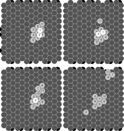
Another mechanism favoring smooth growth was revealed to us watching movies of the full growth from the KMC–MD simulations. In impacts on a small island with an adatom atop, it is possible that the incoming atom and the adatom initially atop the island both end up in the layer of growing island. Thus, not only is the incoming atom inserted into the island, an existing adatom on the island is inserted as well. In these processes the small island is likely to undergo structural changes, perhaps even break up. We tried thirty 18 eV AgAg(111) impacts on a 3 by 3 atom island with an adatom initially on top, with random impact parameters in a surface unit cell neighboring the top adatom (see fig. 11). Of these 30 impacts, both atoms ended up in the growing layer in 19 cases (2 atoms down) , one atom stayed on top of the island in 7 cases (1 atom down), and in 3 cases both atoms stayed on the island (no induced interlayer mobility). In one case 3 atoms ended up on top of the island (1 atom up). Regarding the impact induced break–up of the island, only in 8 cases did the 11 atoms end up as one connected island, while in 22 cases one or more atoms ended up separated from the original island.
8 Summary of MD simulations of single impacts
In summary we can categorize the collision–induced events as follows:
-
Adatom/vacancy formations. The impact causes the digging up of atoms from the surface layer.
-
Insertions. Near descending steps, the incoming atom can be incorporated into the upper terrace. Insertion can also happen for impacts on small islands. Adatoms initially residing above descending steps can also be inserted due to an energetic impact.
-
Pile–ups. Near ascending steps, impacts below the step can result in net growth on the upper terrace.
-
Step edge restructurings. Impacts near steps can change the step edge structure.
-
Island break–ups. Impacts on small islands can cause the island to break up into several pieces. Also, impacts near straight steps can result in adatoms detaching from the step and ending up isolated.
-
Horizontal mobility. Incoming atoms may be displaced horizontally before thermalizing. Also, all the events above involve some induced horizontal mobility.
Some of these events must be characterized as energy–induced defect formations, leaving the surface in a higher energy state when compared to a thermal deposition. Adatom/vacancy formations, pile–ups and island break–ups are such examples. Insertions, on the other hand, can take the surface to a lower energy state, by incorporating the incoming atom or other adatoms initially residing above descending steps. In this respect insertions are examples of energy–induced annealing of defects. However, as we have seen, insertions may be accompanied by an energy increasing restructuring of the step edge, by creating step edge defects like kinks. Also, step edge restructurings are defect formations for impacts on initially straight steps, but for impacts near rough steps, they could be annealing events.
One of the questions one might hope to answer by doing these molecular dynamics simulations of single impacts is what the nature of the energy–induced mobility is. Does the energy, for example, cause a local heating, and can we then understand the increased mobility to be a result of a locally higher temperature? Or is the impact induced mobility more ballistic in nature? Based on the results presented here, we conclude that for these low–energy (eV) metal–on–metal impacts, the local heating and increased temperature is the wrong picture. Plots like the one shown in figure 5 indicate that the more relevant picture is one of a clearly ballistic collision sequence that, depending on impact parameter, may result in defect formation or annihilation or both, as discussed above.
B KMC–MD simulations of growth
After having discussed what can happen in the energetic atom–surface collisions by presenting our molecular dynamics simulations of such impacts, let us now turn to the results of the combined KMC–MD simulation of the growth by energetic deposition. We begin by looking at the effect of the energy on the submonolayer growth of Ag/Ag(111). Subsequently we discuss the growth of several layers, and then we discuss how the picture changes for Pt/Pt(111). All the presented KMC–MD simulations are done at a deposition rate of 1 ML/s and with normal incidence.
1 Ag/Ag(111) submonolayer structure
We have simulated Ag/Ag(111) growth at four different incoming energies, 11, 18, 25 and 32 eV, and for thermal deposition, in which case no MD simulations are done. For all the simulations of energetic deposition, we simulate the atom–surface collisions using molecular dynamics for cluster setups as explained in section II C. All cluster setups have Langevin coefficients . At 11 eV we use , at 18 eV and 25 eV we use , and at 32 eV we use . We first show results where the surface temperature is set to 60 K. This temperature determines the rates of various diffusion processes in the KMC part of the simulation, and is also the Langevin temperature and the temperature to which the MD–atoms are initially equilibrated. We later discuss the effect of increasing the surface temperature.
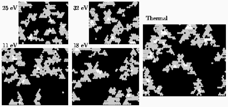
Figure 12 shows the surface morphology at 0.3 ML coverage for Ag/Ag(111) at the different energies, and for the thermal deposition. Focusing on the thermal run, we observe island formation due to surface diffusion. These islands are dendritic with very irregular step edges due to limited diffusion along the step edges at this low temperature. We also observe that the branches of the dendritic islands have preferred growth directions perpendicular to the so-called A-steps. This is because of the asymmetry in the corner diffusion in the EMT barriers, see table I. When a diffusing adatom attaches to the island at the abundant corner–sites, they subsequently preferentially move to the A-step, causing growth in that direction [26].
When comparing the thermal run with the various energetic depositions in figure 12, there is one striking difference. For the energetic depositions, in particular at 25 and 32 eV, we observe a higher density of smaller islands. This is even more clearly shown in figure 13, where we show the island densities as a function of coverage in the lower panel. The figure shows that for not too high coverages the island densities during energetic depositions are higher than that for the thermal deposition — for 25 and 32 eV they are significantly higher. The mechanism giving rise to this increased island density at the higher energies is the formation of adatom/vacancy pairs in the energetic atom–surface collisions, as discussed in section III A. Dimers are either created directly, or they are formed with an increased probability by the two adatoms that result from a collision–induced adatom/vacancy creation. At 32 eV even trimers may be formed directly. The formation of a dimer does not necessarily nucleate a new island, since these dimers are mobile in the KMC–diffusion model, and hence can diffuse on the surface and attach to an existing island. However, the dimers move more slowly than single atoms — they have a shorter diffusion length on the time–scale of the deposition rate, resulting in a higher island density.

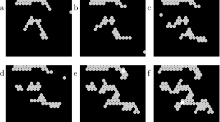
In section III A we found the energy onset of collision induced adatom/vacancy formations to be around 20 eV. The lower panel of figure 13 shows an increased island density even at 11 eV. At this energy the island density is increased around 0.1 ML due to energy–induced breaking up of existing islands into smaller pieces. Figure 14a-d shows the evolution of an island during the 11 eV energetic deposition. From a to b, the island has grown from 17 atoms to a total of 22 atoms, but is also broken into two pieces. The breaking up of the island is not due to thermally activated mobility, but rather is the result of an impact on the very narrow island. From b to c the island grows further, and then from c to d one of the pieces again breaks into two. This break up is also caused by an energetic impact. The island now consists of three pieces. And it is counted as three when the island density plotted in figure 13 is calculated. From d to e two of the pieces have coalesced by further growth, and in f at a total coverage of 0.15 ML, the island has grown and coalesced into one connected piece.
For thermal deposition the island density is a very useful concept, because the average distance between islands actually is a good measure for the typical island separation. The reason for this is that the islands are nucleated by the random diffusion and aggregation of adatoms. In the vicinity of existing islands, adatoms diffuse and attach at the island edge, and this gives rise to a “denuded zone” around the island with a low adatom concentration, and hence with strongly reduced probability of nucleating new islands. As a result islands on the surface tend to be approximately equally spaced, with a spacing determined by the diffusion of the adatoms. As also discussed by Esch et al.[14], this does not necessarily hold for energetic deposition, since islands can be created very close to existing ones. Here it happens by the breaking off of pieces of existing islands. It could also possibly happen by the direct nucleation of new islands by impacts on the surface near existing islands.
In the thermal case, because of the separation of the islands, coalescence sets in at 0.4-0.5 ML coverage, and the island density then drops down. The example in figure 14 of energetic deposition shows coalescence of the pieces of the island as early as 0.1 ML. The little islands created by breaking off pieces of existing islands do not survive for long. In the upper part of the pictures in figure 14a-f is a separate island which has been nucleated independently by the diffusion of adatoms. The two islands in figure 14f are both nucleated by surface diffusion and behave much like islands formed in thermal deposition. They coalesce around 0.5 ML coverage.
Also at 18 eV we see an increased island density setting in around 0.25 ML, and by watching growth movies, we identify the mechanism to be breaking off little pieces of the rather dendritic islands. These little islands usually have short lifetimes before they again coalesce with the bigger island. At 11 and 18 eV the island density plotted in the lower panel of figure 13 can be interpreted as the thermal island density plus short–lived fluctuations above this level due to breaking off pieces of islands.
At 25 and 32 eV adatom/vacancy pairs are formed in the atom–surface collisions. Here the island density is determined first by the fraction of impacts resulting in 1 adatom, 2 adatoms, dimers etc. and then the diffusion of these species. In addition to this, there will be relatively short lived fluctuations due to the breaking up of existing islands into pieces.
In section III A we identified energy–induced processes taking place near steps on the surface which could affect the smoothness of the grown surface because they involve interlayer atomic mobility. The importance of these processes is of course determined by the total step density on the surface during the growth. In the upper panel of figure 13 we plot the step density, defined as the number of lattice sites occupied by atoms with less than 6 neighbors in the same layer divided by the number of sites in one layer (the unit is ML — monolayers). For thermal deposition the step density can be estimated from the island density, the coverage and a fractal dimension of the island. For the energetic depositions, we see something different. The increase in island density below 0.5 ML at 11 and 18 eV, is not reflected in an increase in step density. The islands formed by breaking off pieces from existing islands do not contribute to the step density in the same way as islands nucleated by diffusion.
At 25 and 32 eV, on the other hand, we see a significantly increased step density at not too high coverages. This is due to islands nucleated from the relatively slow diffusion of dimers resulting from collision–induced adatom/vacancy creations. But again, we do not have a simple relation between island density and step density. At 25 eV we observe higher island density than at 32 eV, but we observe higher step density at 32 eV. While the step density is obviously an important quantity in energetic deposition, we conclude that the island density here is a much less useful concept than it has proven to be for thermal deposition.
In summary, we find that energetic deposition increases island densities and step densities. Island densities are increased by breaking existing islands into pieces, and at the higher energies because of collision–induced adatom/vacancy formation. Only islands formed by the latter mechanism give rise to an increased step density.

2 Ag/Ag(111) — growth of the first few layers
We now move on to a discussion of our results for the growth of several atomic layers of Ag on Ag(111). Our primary focus will be on the smoothness of the growth, and how the smoothness is affected by the incoming energy.
Figure 15 shows the normalized anti–phase intensity which would be measured in anti-phase scattering of He[35], RHEED, [36], LEED [37] or X-rays[38], for our thermal and energetic deposition simulations. The intensity is calculated from the simulations as a function of time, using the expression , where is the fractional coverage in the i’th layer.
At 60 K there is no thermally activated interlayer mobility. Hence, for the thermal deposition, adatoms landing on top of existing islands will stay there. Islands are nucleated on top of islands, and multi–layer growth results. The anti–phase intensity drops rapidly to zero. Figure 15 shows that, when the surface is grown by energetic deposition, oscillations in can be induced. The damped oscillations in correspond to a decaying layer–by–layer growth where the surface partly recovers its initial flatness after each atomic layer is deposited.

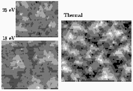
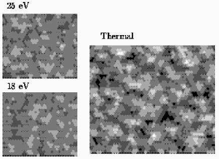
That the surface grown by energetic deposition is more smooth than that grown by thermal deposition can be seen more directly from figure 16, which shows the surface morphology after 3 monolayers deposited, with the gray scale indicating the height above the initial surface, for 18 and 25 eV and for thermal deposition. The same effect is evident in figure 17, which shows the coverage in each atomic layer as a function of the total amount deposited for 25 eV and for the thermal deposition. After thermal deposition of three monolayers, growth of the 6th layer sets in while the second layer is still not completed. At the same total coverage in the 25 eV deposition, the third layer is almost complete, there is some growth in the fourth layer, and only a fraction of a percent of the fifth layer is occupied by atoms.
The fact that using energetic deposition promotes the growth of flat surfaces is consistent with our results for the energy–induced atomic mobilities in the atom–surface collisions presented in section III A. At 60 K thermal interlayer mobility can be neglected. It is the energy–induced insertions for impacts near descending steps which lead to the growth of more smooth surfaces — impact parameters where the incoming atom would stay on top of an existing island in thermal deposition but, due to the energy, now result in lateral growth of the island.
Figure 15 shows that the magnitude of the oscillations of gradually increase when the energy is increased from 0 eV to 25 eV. But by increasing the energy further to 32 eV the oscillations are again reduced. There is an optimal energy around 25 eV for growing smooth surfaces. This is exactly what is predicted from figure 9, which shows the statistics of possible outcomes of impacts near straight steps. Figure 9 shows a maximum of insertion events at 18 eV, pile–ups setting in at 25 eV and dominating over the insertions at 32 eV. Based on figure 9, one might have expected an optimum for growing smooth surfaces at 18 eV, and one might ask why we find this optimum to be closer to 25 eV. Several things play a role: 1) figure 9 shows the result for straight B-steps, but the islands at this temperature are quite small, and have irregular step edges. This might shift the balance of the insertion events to pile–ups to have the optimum at higher energies, and 2) the overall importance of the energy–induced events near the steps will increase with the step density and, as we have discussed above, the step density increases with increasing deposition energy after the onset of energy–induced adatom/vacancy formations. At 25 eV, where the insertion events still dominate over the pile–ups at the straight steps, the total energy–induced downward mobility is increased due to the energy–induced increase in step density.

3 Higher surface temperatures
This takes us to the discussion of the effect of surface temperature during growth by energetic deposition. Figure 18 shows that, for growth at 25 eV, if we increase the surface temperature from 60 K to the 105 K the magnitude of the first oscillation in is reduced approximately by a factor of 3. At 105 K the thermal interlayer mobility is still very low, but the diffusion of the adatoms on the terrace has sped up significantly, reducing the island density, and hence the step density. In addition to this the mobility along the island edges has increased, making islands more compact, and reducing the step density even further. Thus the total energy–induced downward mobility near the step edges is reduced, and the surface grows rough more rapidly. It should be evident that the important parameter here is not the surface temperature itself, but rather the step density, and possibly the step edge structure. Due to the very low barrier for surface diffusion of adatoms on Ag(111) (which is underestimated in the EMT), we have to go to the low temperatures used in our simulations to see an effect of the energy on the smoothness of the surface grown.
As the temperature increases even further, the island and step densities decrease to such an extent that the effect of the incoming energy on the surface height distribution is negligible. However, there can still be a strong effect of the energy on the island density. For example, in (slightly flawed [39]) KMC–MD simulations of 25 eV Ag(111) growth at 200 K the energetic beam no longer changed the surface height distribution, even though the island density changed by a factor of up to 20 compared to thermal growth. However, we have found this to be strongly dependent on details of the implementation of the KMC diffusion model. First of all, the effect depends strongly on the mobility of the small clusters of atoms nucleated in energetic impacts. In the KMC model presented in this paper, these clusters are rather mobile due to periphery diffusion of their atoms, hence reducing the energy effect on island densities. Another subtle but important factor is the efficiency with which diffusing dimers and trimers can fill in the isolated vacancies created in energetic impacts. In EMT this readily happens. However in KMC models, where we do not allow this recombination, the concentration of vacancies may build up to an extent where it hinders the diffusion of the small clusters of atoms, and hence results in a higher island density (a point also made by Esch et al. [14]).
4 Pt/Pt(111) submonolayer structure
We now present the results of KMC simulations of thermal and KMC-MD simulations of 18 eV and 25 eV energetic deposition of Pt/Pt(111) and compare these results to the case of Ag/Ag(111). All the Pt KMC-MD simulation are done with a surface temperature of 80 K and a deposition rate of 1 ML/s. The MD part of the simulations is done using setups with Langevin coefficients and .
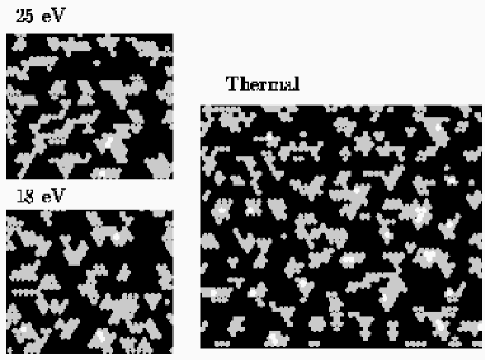
Figure 19 shows the surface morphology after the deposition of 0.3 ML of Pt on Pt(111) for thermal deposition and for the two energies. Compared to the Ag/Ag(111) simulations, there is a much higher thermal island density. This is of course due to the higher energy barriers for surface diffusion on Pt. Because of the higher density of islands, they are smaller and tend to be less branched. Thus in the case of Pt, the submomolayer structure obtained by energetic depositions at 18 and 25 eV is very similar to the thermal submonolayer structure. This is also apparent from figure 20, which shows the island and step densities, as figure 13 did for Ag. At low coverages the island and step densities for the energetic depositions follow the corresponding curves for the thermal deposition quite closely. If there is a difference at all, the energy slightly reduces the island density. This could be explained by short ranged energy–induced horizontal mobility. Around 0.7 ML the energetic step densities level off, indicating smooth growth, whereas the thermal one continues to increase as the surface roughens. We recall from figure 10 that 25 eV is below the onset for energy–induced adatom/vacancy formations for PtPt(111) impacts, consistent with the unchanged island density. Apparently, the breaking up of existing islands is also not pronounced here — probably as a consequence of the less branched island structure, and the stronger Pt–Pt bond energies.

5 Pt/Pt(111) — growth of the first few layers

While the 18 eV and 25 eV energetic deposition has no influence on the surface morphology at low coverages, it has a significant influence as the growth progresses. Figure 21 shows fairly strong and slowly damped oscillations in the simulated anti–phase intensity being induced by the energy. At 25 eV the periodicity in the growth of each layer is evident from figure 22 (i.e., the curves for successive layers look the same). For thermal growth, on the other hand, the completion of each layer spreads out over an increasing period of time.

Two main factors play a role in making the energetic growth so smooth in the case of Pt. First, figure 10 shows a pronounced energy–induced mobility for impacts near steps that favors smooth growth, i.e., for impacts above the step, there is a high probability of energy–induced insertions. We do not see induced pile–ups for impacts below the step at these energies. Second, the step density for Pt/Pt(111) at this temperature is very high. As was the case for Ag we expect the advantageous effect of the energy to die away with increasing surface temperature, as the step density decreases with increased surface diffusion.
IV Discussion of results
Here we summarize and discuss our results from simulating growth by energetic deposition. Our results from our study of the possible outcomes of single impacts on different surface configurations were summarized in section III A 8. We found energy–induced defect formation mechanisms, such as adatom/vacancy formations, pile–ups, step edge restructurings and break–ups of existing islands. We also found energy–induced defect annihilation mechanisms, in particular insertion of atoms into horizontally growing layers. For the energies in this study we in general found the energy–induced mobility to be limited to a range of a few (5) atomic distances.
In doing the KMC-MD simulations of the entire growth process, we have seen that the energy–induced atomic mobility can affect island densities in two ways. First, for energies above a certain threshold (20 eV for Ag), the energy–induced formation of adatom/vacancy pairs and direct formation of dimers and trimers on the surface increases the island density. In our simulation these small clusters of atoms diffuse only slowly on the surface, giving rise to the reduced island separation. It is an important characteristic for islands formed in this manner that they are nucleated by diffusion and aggregation: they tend to repel each other via their diffusional fields, and are well separated as is the case for islands formed in thermal growth. Hence, they coalesce in the late stages of the growth of a monolayer. Second, the energetic impacts increase the island density in a separate way, by breaking off clusters of atoms from existing islands. While this process may give rise to new islands, they are always nucleated very close to existing islands, and are qualitatively different. In the Ag/Ag(111) simulations, we have seen that they do not contribute to the step density, in contrast to islands nucleated by diffusion. They have a very short life time, either because they diffuse to join the original island, or because they grow and coalesce at a much earlier growth stage.
We have seen that at low temperatures using energetic deposition can change rough thermal growth to smooth layer–by–layer growth. As usual, this is expected eventually to decay into rough growth as the number of layers increases [40]. We have done simulations at temperatures where thermal interlayer mobility is frozen out, and have found that energy–induced insertions of atoms into growing layers can be sufficient to give layer–by–layer growth. However, energy–induced pile–ups, which set in at a higher energy, can cause the opposite effect. For this reason we find that there is an optimal energy for layer–by–layer growth — for Ag it is approximately 25 eV. We expect the existence of such an optimum to be general. Pile–ups are likely to dominate over insertions at higher energies; for insertions only the incoming atom or other atoms residing above descending steps can be inserted, while the number of atoms that can pile up is not similarly limited.
Since the energy–induced insertions are limited to impacts within a short range of descending steps, we have seen that a high step density is needed for energy–induced smooth growth. While the use of energetic deposition can itself assist in increasing the step density, we have seen the energy induced layer–by–layer growth dies away with increasing temperature in the case of Ag/Ag(111). The horizontal diffusivity for this system is very high, and the two dimensional islands readily grow very large as the temperature is increased, giving a very low step density. However, how efficient the energetic beam is in increasing the island density depends on many details of the atomic potential energy landscape. In some cases this efficiency can be very high. Therefore, in some systems which have a low step density when thermally grown, it is possible that an energetic beam might increase the step density sufficiently for the energetic-beam insertions to give rise to smooth growth.
V Discussion of method
We now turn to a general discussion of our Kinetic Monte–Carlo Molecular Dynamics method for simulating crystal growth by energetic deposition. We wish to address the validity of the method, its advantages and disadvantages, and how we find it useful in providing information about the energetic growth.
Kinetic Monte–Carlo treats the thermal diffusion as a sequence of uncorrelated atomic hops, and assumes these diffusion hops to be instantaneous. In reality, a diffusion hop in a crystalline environment has a duration time of roughly a picosecond, the typical time an atom spends on top of the barrier while crossing it. The Kinetic Monte–Carlo formalism is correct when the times between various kinds of hops is much larger than . (The time between hops is the inverse rate of the diffusion process, given by the Arrhenius formula with the barriers in Table I.) In the same way, KMC-MD is correct when the time between hops is larger than , the duration of our MD simulation of the non-thermal collision–induced mobility. During we neglect thermal mobility outside and across the boundaries of the region of the MD simulation. This approximation only limits the validity of the simulation to the extent that this mobility would correlate to the atomic rearrangements in the impact region. The collision is treated as instantaneous by the KMC algorithm, so the total mobility outside the impact region is correctly accounted for, whereas inside the region thermal mobility within is doubly accounted for. While this should be kept in mind, we don’t expect it to have any significance for the simulations presented in this paper, because diffusion is so slow compared to .
The KMC–MD method also carries over the other usual limitations of KMC. One of these is that the KMC part of the simulation must be done on a lattice. In the present simulations of growth of fcc(111) surfaces, we neglect the presence of the off–lattice hcp binding sites in the KMC part of the simulation, and hence we have to move atoms trapped in these sites at the end of an MD simulation to neighboring fcc sites. This is severe only if growth in practice would take place on the hcp sites. Growth partly on hcp sites, partly on fcc sites, would give rise to complicated structures and dynamics at the stage of coalescence of these islands, a scenario we are unable to study with the KMC–MD method. As noted earlier, the favorable hcp site is an artifact of the EMT potential we use, and these issues are most likely not relevant experimentally.
The KMC–MD method must be based on a model potential for the atomic interactions, in this case the EMT. While the EMT includes many qualitative and to some extent quantitative features of the interaction of late transition and noble metals, it is not an exact potential. In the case of Pt(111), for example, it is found that a simple scaling of the EMT energy barriers by a factor of 1.6 as input for a KMC simulation of thermal growth gives a good agreement with experimental island densities, transition of fractal to compact islands, and the appearance of reentrant layer–by–layer growth at low temperatures [25, 30, 27]. A common scaling factor of all energy barriers would not be a severe discrepancy — it merely corresponds to a scaling of the temperature.
While the approximations made in effective medium theory prevent us from controlled predictions of exactly how a real material would grow by energetic deposition, the method still includes the right ingredients to be a useful tool for our purposes: to examine how the use of energetic particles may influence the crystal growth; and to identify mechanisms and evaluate their relative importance, as has been done in the previous sections. We have demonstrated that the KMC–MD method can indeed be used to elucidate the important interplay between energy–induced mobility and thermal surface diffusion.
One could imagine an alternative way of doing these simulations of growth by energetic depositions. First make a complete table of all possible outcomes of single atom–surface collisions listed together with their relative statistical significance, and for all relevant local surface configurations. Then perform a KMC simulation, which for each impact would choose the resulting local configuration from such a table. The present simulation study shows what an enormous task that would be. In section III A we considered impacts on the flat surface and near one type of straight step, and found a dependence on the step position up to 5 atomic distances away. Imagine the table of collision events needed to correctly account for the evolution surfaces presented in section III B!
A major advantage of the present method is that it allows one to evolve the surface by depositing energetic atoms without making any assumptions about the effect of the energy. From each simulation we can in principle record exactly the contributions of various types of energy–induced atomic mobilities. The method correctly convolves the distribution of possible outcomes of energetic impacts on a given local configuration with the distribution of different local configurations during the crystal growth. The energy–induced microscopic mechanisms acting are not assumed, but on the contrary revealed by the method. One example of this is the insertion of atoms residing atop islands prior to impacts, as discussed in section III A 7.
The main disadvantage of the method is that it is very time consuming computationally. The MD simulations are expensive, and a new simulation for every deposited atom is needed. Even for the relatively small surface areas considered here, a thousand to a few thousands of MD simulations are needed per monolayer. In order for the method to be feasible, it is essential that the island density not be too low. Big islands require a larger surface area and hence a larger number of MD simulations per monolayer. Our simulations ran for weeks to months on reasonable 1997 workstations.
Our method is not well suited for parallelization. The bulk of the CPU time is running the MD for the atomic impacts. Each MD simulation is small and parallelization by subdivision would give rise to a considerable communication overhead. The current size of the simulation is set by the need to have an impact not be affected by the periodic boundary conditions: the impact and its further diffusive evolution must not feel its periodic images. Distribution of the impacts among different processors would necessarily involve artificial simultaneous depositions in different areas of the surface. For these depositions to be unaffected by one another, it would seem that the same system-size per processor must be needed: parallelization does not allow more monolayers per month.
Our new method, by combining MD for the impact with KMC for the diffusive motion between impacts, allows for realistic simulations of surfaces grown with energetic beams at realistic growth rates of monolayers per second. Good simulations, however, take a week or more per monolayer deposited.
VI Acknowledgements
We thank K.W. Jacobsen, K. Bhattacharya, T. Curcic, and C. Henley for helpful discussions. This research was supported by the Cornell Center for Materials Research under NSF award number DMR-9632275. The simulations were done partially at the Cornell Theory Center, which receives major funding from the National Science Foundation (NSF) and New York State, with additional support from the National Center for Research Resources at the National Institutes of Health (NIH), IBM Corporation, and other members of the center’s Corporate Partnership Program.
REFERENCES
- [1] Fractal Concepts in Surface Growth, A.-L. Barabasi and H. E. Stanley, Cambridge University Press, 1995.
- [2] F. A. Smidt, Int. Mater. Rev. 35, 61 (1990); F. A. Smidt and G. K. Hubler, Nucl. Instrum. Methods Phys. Res. B 80/81, 207 (1993).
- [3] J. E. Greene in Handbook of Crystal Growth, edited by D. T.J. Hurle (Elsevier, New York, 1993), Vol. 1.
- [4] W. Shindo and T. Ohmi, J. Appl. Phys. 79, 2347 (1996).
- [5] N. E. Lee, G. Xue, and J. E. Greene, J. Appl. Phys. 80, 769 (1996).
- [6] B. W. Karr, Y. W. Kim, I. Petrov, D. B. Bergstrom, D. G. Cahill, and J. E. Greene, J. Appl. Phys. 80, 6699 (1996).
- [7] J. W. Rabalais, A. H. Al-Bayati, K. J. Boyd, D. Marton, J. Kulik, Z. Zhang, and W. K. Chu, Phys. Rev. B 53, 10781 (1996).
- [8] E. F. Fullerton, J. Pearson, C. H. Sowers, S. D. Bader, X. Z. Wu, and S. K. Sinha, Phys. Rev. B 48, 17432 (1993).
- [9] E. F. Fullerton, D. M. Kelly, J. Gimpel, I. K. Schuller, and Y. Bruynseraede, Phys. Rev. Lett. 68, 859 (1992).
- [10] H. Ueda, O. Kitakami, Y. Shimada, Y. Goto, and M. Yamamoto, Jpn. J. Appl. Phys. 33, 6173 (1994).
- [11] S. Nagamachi, M. Ueda, H. Sakakima, M. Satomi, and J. Ishikawa, J. Appl. Phys. 80, 4217 (1996).
- [12] M. Kallf, M. Breeman, M. Morgenstern, T. Michely, and G. Comsa, Appl. Phys. Lett. 70, 182 (1997).
- [13] T. Michely and C. Teichert, Phys. Rev. B 50, 11156 (1994).
- [14] S. Esch, M. Breeman, M. Morgenstern, T. Michely, and G. Comsa, Surf. Sci. 365, 187 (1996).
- [15] S. I. Kim, Rev. Sci. Instrum. 67, 908 (1996); S. Nagamachi, Y. Yamakage, M. Ueda, H. Maruno, J. Ishikawa, 67, 2351 (1997); B. H. Cooper, private communication.
- [16] M. Villarba and H. Jónsson, Surf. Sci. 324, 35 (1995).
- [17] M. Kitabatake and J.E. Greene, Thin Solid Films 272, 271 (1996).
- [18] J.A. Spraque and C.M. Gilmore, Thin Solid Films 272, 244 (1996).
- [19] C.M. Gilmore and J.A. Spraque, Phys. Rev. B 44, 8950 (1991).
- [20] C.L. Kelchner and A.E. DePristo, Surf. Sci. 393, 72 (1997).
- [21] T. Ohashi, K. Miyake and K. Ohashi, Nucl. Instr. and Meth. in Phys. Res. B 121, 40 (1997).
- [22] See e.g. G. Betz and W. Husinsky, Nucl. Instr. and Meth. in Phys. Res. B 122, 311 (1997).
- [23] K.W. Jacobsen, J.K. Nørskov and M.J. Puska, Phys. Rev. B, 35 7423 (1987); K.W. Jacobsen Comments Cond. Mat. Phys. 14, 129 (1988); K.W. Jacobsen, P. Stoltze and J.K. Nørskov, Surf. Sci. 366, 394 (1996).
- [24] M. Jaraiz, G. H. Gilmer, J. M. Poate, and T. D. de la Rubia, Appl. Phys. Lett. 68, 409 (1996); M. J. Caturla and T. D. de la Rubia, preprint.
- [25] J. Jacobsen, K.W. Jacobsen, P. Stoltze and J.K. Nørskov, Phys. Rev. Lett. 74, 2295 (1995).
- [26] H. Brune, H. Rö der, K. Bromann, K. Kern, J. Jacobsen, P. Stoltze, K.W. Jacobsen and J.K. Nørskov, Surf. Sci. 349, L115 (1996) .
- [27] The ability of EMT to reproduce Pt and Ag growth experiments has been discussed previously [25, 26, 30]. Early experimental results for Pt/Pt(111) showed compact island shapes which could not be predicted by EMT, however new results from the same experimental group improves the agreement [M. Kalff, Th. Michely, G. Comsa, submitted for publication; Th. Michely, private communication.] We also note that recent ab initio calculations predict a nearly vanishing Ehrlich-Schwoebel barrier on the Pt(111) A–steps [P. J. Feibelman, preprint], whereas EMT predicts a more substantial one.
- [28] A.F. Voter, Phys. Rev. B 34, 6819 (1986); K.A. Fichthorn and W.H. Weinberg, J. Chem. Phys. 95, 1090 (1991).
- [29] G.T. Barkema, O. Biham, M. Breeman, D.O. Boerma and G. Vivaldi, Surf. Sci. 303, 25 (1994); M. Hohage, M. Bott, M. Morgenstern, Z. Zhang, T. Michely and G. Comsa, Phys. Rev. Lett. 76, 1304 (1996).
- [30] J. Jacobsen, K.W. Jacobsen and J.K. Nørskov, Surf. Sci. 359, 37 (1996), J. Jacobsen, K.W. Jacobsen and J.K. Nørskov, Scanning Microscopy, in press.
- [31] A.E. DePristo and H. Metiu, J. Chem. Phys. 90, 1229 (1989).
- [32] M. P. Allen and D. J. Tildesley, Computer Simulations of Liquids, Clarendon Press, Oxford, 1987.
- [33] G. Rangelov, T. Fauster, U. Strüber, and J. Küppers, Surf. Sci. 331–333, 948 (1995) .
- [34] P. J. Feibelman, J. S. Nelson, and G. L. Kellog, Phys. Rev. B. 49, 10548 (1994); for Ag and Pt: J. J. Mortensen, B. Hammer, P. Stoltze, O. H. Nielsen, K. W. Jacobsen, and J. K. Nørskov, The 18th Taniguchi Symposium on “Elementary Processes in Excitations and Reactions on Solid Surfaces”, Ed. A. Okiji, Springer Verlag, 1996;
- [35] G. Rosenfeld, N. N. Lipkin, W. Wulfhekel, J. Kliewer, K. Morgenstern, B. Poelsema, and G. Comsa, Appl. Phys. A 61, 455 (1995).
- [36] T. Sakamoto, T. Kawamura, S. Nago, G. Hashiguchi, K. Sakamoto, K. Kuniyoshi, J. Cryst. Growth, 81, 59 (1987).
- [37] M. Henzler, Surf. Sci. 298, 369 (1993).
- [38] “X-Ray Scattering Study of the Surface Morphology of Au (111) During Ar+ Ion Irradiation”, M. V. Ramana Murty, T. Curcic, A. Judy, B. H. Cooper, A. R. Woll, J. D. Brock, S. Kycia, and R. L. Headrick, Phys. Rev. Lett., 80, 4713 (1998).
- [39] These simulations were done at 25 eV using MD setups with and , which overestimates the adatom/vacancy production somewhat. However, using converged MD system sizes, the same result would likely be obtained at a slightly higher energy, probably approximately 30-35 eV.
- [40] J. Jacobsen and J.P. Sethna, to be published in Surface Science Letters.