[
Supercurrent switching in Three- and Four- Terminal Josephson Junctions
Abstract
Control of the Josephson current by varying a gate current has recently been demonstrated in both 4-terminal and 3-terminal junctions. We show that, when the the gates are weakly coupled to the Josephson junction, the Josephson current versus gate current (or versus gate voltage) relation is the same for both the 4- and 3- terminal geometries. At low temperature, the supercurrent switches abruptly as a function of the gate voltage, but only slowly as a function of the gate current.
pacs:
PACS numbers: 74.80Fp, 74.50+r, 73.20.Dxsubmitted to Journal of Applied Physics
]
I Introduction
Transistors with superconducting sources and drains have been fabricated over the last 10 years, using field effect control of the supercurrent flow. [1] For the field effect to change carrier density typically requires a gate voltage of the order of volts, while superconducting energy gaps () are at best of order millivolts. To overcome this incompatibility in voltage scales, van Houten suggested using quantum confinement [2] in the channel to incorporate a new small energy scale into the transistor. Due to the added confinement energy, a small change in gate voltage can produce a large change in the supercurrent flow.
A small energy scale occurs naturally in the superconducting transistor, even without the added quantum confinement. The two superconductors themselves form a special type of ‘barrier’ for electrons, where the electrons ‘Andreev reflect’ for the superconductor as a hole. [3, 4] Repeated Andreev reflections from the two superconductors form a closed path, leading to energy level quantization inside the device channel. These ‘Andreev energy levels’ form inside the superconducting gap, with more bound levels forming as the channel length increases (just as in the standard type of quantum well). A large fraction of the Josephson current flows through the Andreev levels [5, 6, 7], where a quasi-particle moving once around this closed path corresponds to the transfer of a pair of electrons across the device channel.
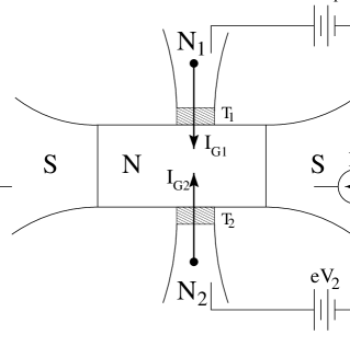
Figure 1 shows a type of gated Josephson junctions used in two different recent experiments [8, 9] to control the Josephson effect. The gate terminal are all normal metals (N1,N2) held at voltages (,). The superconductors (S) are grounded. Electrons can tunnel from the gates into the normal region (N) of the Josephson junction with probabilities (). Setting the tunneling probability decouples one of the gates from the Josephson junction, forming a three terminal junction.
Morpurgo et al. [8] have recently used current flow through the two opposing gates to switch off the Josephson current in a 4-terminal junction. Control of the Josephson current with a gate voltage (or current) in a more conventional 3-terminal geometry has also been shown by Schälpers [9] et al.. Both recent experiments are based on the mechanism of van Wees et al. [6] that, because the superconductor cannot inject electrons into the bound Andreev levels, the electrochemical potential of the bound levels will float to the probe voltage (e.g. in a 3-terminal geometry) rather than to the electrochemical potential of the superconductors (). Refs. [10]-[14] have also used this principle to analyze the the current flow in different types of gated Josephson junctions.
II Four Terminal Junction
Consider next the Andreev level occupation in a 4- terminal Josephson junction. The occupation factor for the Andreev levels (inside the normal region (N) of the Josephson junction where the Andreev levels exist) is now given by
| (1) |
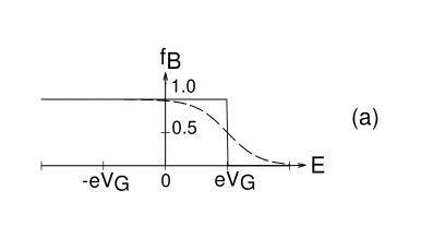
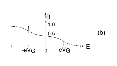
The occupation factors and in Eq. (1) are the Fermi factors of the two gates, namely and . Here and are the gate voltages and is the equilibrium Fermi factor. Equation (1) states that the occupation factor for an electron in the normal region is simply the probability that the electrode originated from probe times the occupation factor of probe . The occupation factor in Eq. (1) is the same as for a small metallic grain, semiconductor quantum dot, etc. connected to two normal metal leads. For the 3-terminal device (), Eq. (1) gives the occupation factor of the bound levels is simply the Fermi factor of the gate . The bound level occupation factors in the 3- and 4- terminal devices are shown in Fig. 2.
The Josephson current flow through the either device in Fig. 1 is divided into two different energy regions [7] as . The ‘continuum’ current flows at energies outside the superconducting gap (), and is essentially not affected by the additional gates (neglecting gate leakage). [11] The current is therefore essentially the same for both 3-terminal and 4-terminal devices. The ‘bound level’ current flows in the energy range within of the Fermi level (), and is given by [11]
| (2) |
Here is the energy of the Andreev level and is the current carried by the level. In the weak coupling limit (, ), where the wavefunctions inside the normal region are essentially unchanged by adding the gates, is the current carried by bound levels in the Josephson junction before adding the gates. Inserting Eq. (1) into Eq. (2) gives
| (3) | |||
| (4) |
Equations (1)-(4) are easily generalized to any number of gates connected to the Josephson junction.
Morpurgo et al. used a symmetrical device (for which we define the gate coupling ), passing a gate current , so that the gate voltages satisfy . One can easily verify [11] that the bound level current does not depend on the sign of the gate voltage in a 3-terminal structure, so in this limit Eq. (4) reduces to
| (5) |
To plot the Josephson current versus gate current (for the symmetrical 4-terminal device in the weak coupling limit), we can therefore use the same formalism previously developed [11, 13] for the 3-terminal junction. Specifically, we use the one-dimensional Josephson junction model of Ref. [13], where the normal region extends over and includes a tunnel barrier having transmission probability at . Ref. [13] uses the simplest type of scattering matrix to describe the connection of the gate to the Josephson junction, which neglects backscattering of quasi-particles due to the gate. Additional physics may develop if one allows the gate to alter the quasi-particle trajectories through backscattering. [12]
[
]
Even though the 4-terminal device has a ‘double step’ Fermi distribution, shown in Fig. 2(b), this unusual nonequilibrium distribution function is irrelevent to the Josephson current switching. The current is the same as if the bound levels had the standard equilibrium Fermi distribution of Fig. 2(a). The temperature of the electrons in this distribution, whether they are ‘hot’ or ‘cold’, is also not important to the switching effect. Switching of the Josephson current versus gate voltage or gate current will be sharper if the electrons remain ‘cold’. For the 3-terminal device having the distribution function of Fig. 2(a), there is also a voltage drop of across the NS junctions. The total voltage drop between the two superconductors is still zero, as the voltage difference across the left NS junction is the negative of the voltage drop across the right NS junction. In the 4-terminal device, where the average electrochemical potential is equal to that of the superconductors (), there is no voltage drop across either NS junction. The presence of absence of these voltage drops does not (to lowest order) affect the supercurrent flow.
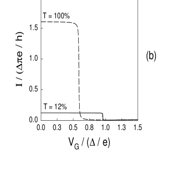
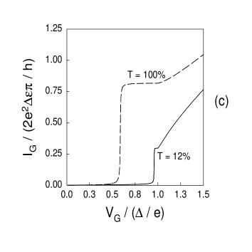
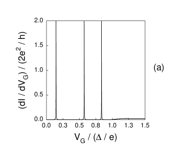
A Short Junction
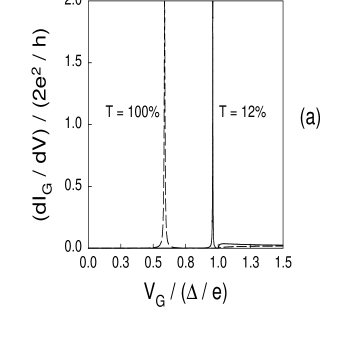
Figure 3 shows the terminal characteristics of a short (, where is the length of the normal region and the coherence length of the superconductors) Josephson junction. The gate couplings in Fig. 3 are weak, with . We fix the superconducting phase difference at . The differential conductance along the gate shows a resonance whenever the gate voltage crosses a new Andreev level in Fig. 3(a), a tool which can be used to perform ‘Andreev level spectroscopy’. The gate current versus voltage in Fig. 3(c) is simply the integral of Fig. 3(a), showing steps in the gate current instead of peaks in differential conductance. The Josephson current versus gate voltage in Fig. 3(b) switches abruptly to zero whenever a new Andreev level is populated. Reducing transmission across the normal region from to in Fig. 3(b) suppresses the Josephson current and pushes the Andreev level closer to the gap edge, pushing the switching voltage close to .
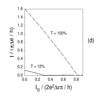
The Josephson current versus gate current is shown in Fig. 3(d). Both the Josephson current switching in Fig. 3(b) and the increase in the gate current in Fig. 3(c) occur over over the same range of voltage, namely the width (in energy) of the Andreev level. The Josephson current therefore decreases quite slowly and gradually with increasing gate current. The fractional occupation of the single Andreev level in this junction () also increases slowly from to during the switching event. Contrast the sharp switching characteristics in the Josephson current versus gate voltage from Fig. 3(b) (roughly a square wave) to the relatively slow change of Josephson current versus gate current in Fig. 3(d) (approximately triangular).
B Long Junction
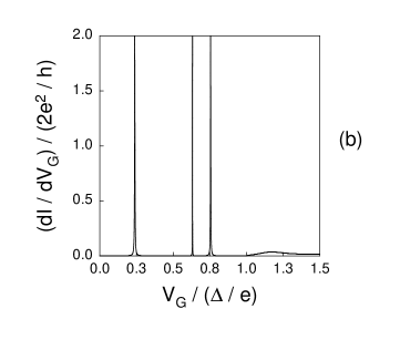
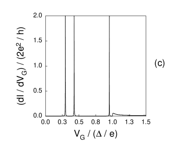
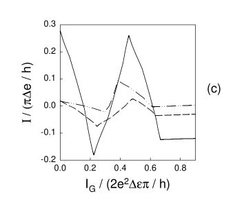
Figures 4 and 5 show the same terminal characteristics for a long () Josephson junction. In long SNS junctions the position of the tunnel barrier has some influence on the size of the Josephson current [7, 13, 15]. We therefore consider a ‘ballistic’ junction with , an ‘asymmetric’ junction with the tunnel barrier of the distance across the normal region ( and ), and a ‘symmetric’ junction with the tunnel barrier in the middle of the normal region ( and ). The gate is again only weakly coupled to the Josephson junction, with . We again fix . This particular long junction has three Andreev levels in the energy range within of the Fermi level (since ), as can be seen from the differential conductance along the gate versus gate voltage in Fig. 4. Only small differences appear in the differential conductance along the gate between the different types of long junctions in Fig. 4.
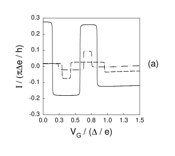
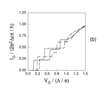
Figure 5 shows (a) the Josephson current versus gate voltage, (b) the gate current versus gate voltage (the integral of Fig. 4), and (c) the Josephson current versus gate current for the three different types of long Josephson junctions. The Josephson current in Figs. 5(a) and (c) changes sign whenever the gate voltage is such that a new Andreev level becomes populated or depopulated [6, 11] (sometimes called a ‘-phase shift’ [10, 14]). A sign change of the Josephson current only occurs in long junctions, as filling or emptying the single Andreev level in a short junction forces the Josephson current to zero. The Josephson current remaining in Fig. 5(a) and (c) when all the Andreev levels are filled (), is the ‘continuum’ current .
The Josephson current switches abruptly with gate voltage in Fig. 5(a), but only gradually with gate current in Fig. 5(c). The with in voltage over which these currents change is again the Andreev energy level width. Andreev level is filling changes the gate current and Josephson current simultaneously, leading again to only slow variation of Josephson current with gate current in Fig. 5(c). The same reasoning explains why the shape of Fig. 5(a) is roughly a square wave, while Fig. 5(c) is roughly triangular.
The ballistic junction (solid lines) always has the largest Josephson current, as seen in Fig. 5(a) and (c). The symmetric junction (dashed lines) displays the so-called ‘giant’ Josephson current [15, 13] as the switching event near in Fig. 5(a), but the asymmetric junction can also display switching currents of the same magnitude. One indeed expects the symmetric tunnel junction to have large switching currents compared to its Josephson current [15], but the asymmetric junction can have these as well when the Andreev gaps are small [13].
Since Ref. [8] uses metals to fabricate the Josephson junction, the quasi-particle trajectories forming the bound Andreev levels will not be the simple types of scattering trajecties assumed in Refs. [11, 13], but will be altered by impurity scattering inside the Josephson junction. [10, 14] In such dirty junctions at very low temperature another energy scale becomes important (the Thouless energy, set by the time for an electron to diffuse across the Josephson junction). This extremely low energy scale does not increase as the superconductor improves, and is not essential to understanding the Josephson current switching (or ‘-phase shifting’). The Josephson current changes sign in long junctions whenever a new Andreev level is populated or depopulated. Populating a new Andreev level in the short junction simply forces the Josephson current to switch off.
C Maximizing Current Gain
We now consider how to maximize the change of Josephson current over the change in gate current while the Josephson current switches. For simplicity we consider only the ballistic junction, . Following Ref. [11], the change in Josephson current is
| (6) |
with the energy dependent coherence length. The change in gate current near a resonance is
| (7) |
where is the gate coupling. The ratio of Josephson to control current is therefore
| (8) |
If we could take the gate coupling to zero, the current gain would become infinite. However, inelastic or phase breaking scattering sets a lower limit on the gate coupling needed for the gate control to affect the Josephson current. [6] If the inelastic scattering time is , we have [11]
| (9) |
The maximum current gain then becomes
| (10) |
where the arrow indicates the short junction limit. The maximum current gain in the ballistic short junction limit is therefore set by the ratio of the superconducting energy gap to the level broadening induced by inelastic or phase breaking scattering. The device of Ref. [9], in the short, ballistic junction limit, shows a current gain of about 20 for small gate currents.
III Conclusions
We have shown the dependence of the supercurrent flow in a three or four terminal Josephson junction on the current passing through a normal metal gate, motivated by two recent experiments. [8, 9] When the gates or gates are weakly coupled to the Josephson junction, desirable for better isolation of gate (control) current from the Josephson current, there is little (or no) difference between the terminal characteristics of the three versus four terminal geometries. The Josephson current in either geometry is a slowly varying function of the gate current, even for the idealized one-dimensional model we have considered in this paper. The Josephson current varies much more rapidly as a function of the gate voltage. Measuring the differential conductance along the gate would also permit direct observation (spectroscopy) of the current carrying energy levels inside the superconducting gap.
In both the transistor fabricated using metals [8] and in compound semiconductors [9], the gates are not well isolated from the device channel. Instead of the tunnel barriers drawn in Fig. 1, only impurity scattering inside the Au metal [8] or two-dimensional electron gas [9], along with possible contact resistances, provide partial gate isolation. Since quasi-particles which are normally trapped inside the Josephson junction can now escape by leaking into the gate, the bound Andreev levels in either device will therefore be very broad. Broad Andreev levels not only broaden the Josephson current switching, but produces gate currents in experiments which are comparable to the supercurrents. As pointed out in Ref. [9], The two dimensional (planar) geometry of the devices used in the two experiments also introduce a type of geometrical broadening [16] which needs to be studied in this context.
IV Acknowledgements
We thank T. Schälpers for communicating his experimental results prior to publication. We gratefully acknowledge support from the MRSEC of the National Science Foundation under grant No. DMR-9400415 (PFB).
REFERENCES
- [1] A.W. Kleinsasser and W.J. Gallagher, ‘Three Terminal Devices’ in Superconducting Devices, S.T. Ruggiero and D.A. Rudman, eds., (Academic Press, New York, 1990).
- [2] H. van Houten, ‘Three-terminal Quantum Box Resonant Tunneling Josephson field-effect Switch’, Applied Physics Letters, 58, 1326 (1991).
- [3] A.F. Andreev, ‘The Thermal Conductivity of the Intermediate State in Superconductors’, Zh. Eksp. Teor. Fiz., 46, 1823 (1964). [Soviet Physics JETP, 19, 1228 (1964)] A.F. Andreev, ‘Electron Spectrum of the Intermediate State in Superconductors’, Zh. Eksp. Teor. Fiz., 49, 655 (1966). [Soviet Physics JETP, 22, 455 (1966)]
- [4] S. Datta, P.F. Bagwell, and M.P. Anantram, ‘Scattering Theory of Transport for Mesoscopic Superconductors’, Physics of Low Dimensional Structures, 3, 1-58 (1996).
- [5] C.W.J. Beenakker, ‘Universal Limit of Critical Current Fluctuations in Mesoscopic Josephson Junctions’, Physical Review Letters, 67, 3836 (1991).
- [6] B.J. van Wees, K.M.H. Lenssen, and C.J.P.M. Harmans, ‘Transmission Formalism for Supercurrent Flow in Multiprobe Superconductor-Semiconductor-Superconductor Devices’, Physical Review B, 44, 470 (1991).
- [7] P.F. Bagwell, ‘Supression of the Josephson Current Through a Narrow, Mesoscopic Semiconductor Channel by a Single Impurity’, Physical Review B, 46, 12573 (1992).
- [8] A.F. Morpurgo, T.M. Klapwijk, and B.J. van Wees, ‘Hot Electron Tunable Supercurrent’, Appl. Phys. Lett. 72, 966 (1997).
- [9] Th. Schälpers, J. Malindretos, J. Neurohr, S. Lacnenmann, A.A. Golubov, A. van der Hart, G. Crecelius, H. Hardtdegen, and H. Lüth, ‘Demonstration of a current-controlled 3-terminal Nb-InxGa1-xAs/InP Josephson contact, submitted to Appl. Phys. Lett. .
- [10] A.F. Volkov, ‘New Phenomena in Josephson SINIS Junctions’, Phys. Rev. Lett., 74, 4730 (1995). Replace the words ‘proximity effect’ with ‘Andreev reflection’ everywhere in this paper (or other papers) to convert to the scattering language used here.
- [11] L. Chang and P.F. Bagwell, ‘Control of Andreev Level Occupation in a Josephson Junction by a Normal Metal Probe’, Physical Review B, 55, 12678 (1997).
- [12] P. Samuelsson, V.S. Shumeiko, and G. Wendin, ‘Long-range Josephson effect in mesoscopic T-shaped Superconductor - Normal Metal - Superconductor Junctions’, Physical Review B, 56, R5763 (1997).
- [13] H.T. Ilhan, H.V. Demir, and P.F. Bagwell, ‘Andreev Level Spectroscopy and Josephson Current Switching in a 3-Terminal Josephson Junction’, preprint cond-mat/9712273.
- [14] F.K. Wilhelm, G. Schön, and A.D. Zaikin, ‘The Mesoscopic SNS Transistor’, preprint cond-mat/9803091.
- [15] G. Wendin and V.S. Shumeiko, ‘Giant Josephson current through a single bound state in a superconducting tunnel junction’, Physical Review B, 53, R6006 (1996). G. Wendin and V.S. Shumeiko, ‘Josephson transport in complex mesoscopic structures’, Superlattices and Microstructures, 20, 569 (1996).
- [16] P.F. Bagwell, T.P.E. Broekaert, T.P. Orlando, and C.G. Fonstad, ‘Resonant Tunneling Diodes and Transistors with a One, Two, or Three Dimensional Electron Emitter’, Journal of Applied Physics, 68, 4634 (1990).