[
Lateral Separation of Macromolecules and Polyelectrolytes in Microlithographic Arrays
Abstract
A new approach to separation of a variety of microscopic and mesoscopic objects in dilute solution is presented. The approach takes advantage of unique properties of a specially designed separation device (sieve), which can be readily built using already developed microlithographic techniques[1]. Due to the broken reflection symmetry in its design, the direction of motion of an object in the sieve varies as a function of its self-diffusion constant, causing separation transverse to its direction of motion. This gives the device some significant and unique advantages over existing fractionation methods based on centrifugation and electrophoresis.
pacs:
PACS numbers:82.45.+z, 87.15.-v, 07.10.-h, 36.20.Ey]
Separation of macromolecules such as proteins and DNA, as well as mesoscopic objects such as cells and latex spheres according to size has many important technological applications, and an immense effort has gone into achieving efficient, well controlled and high resolution separation techniques[1, 2, 3]. Two of the main avenues that have been employed extensively are electrophoresis[2] and centrifugation[3]. These two methods are somewhat complementary since the former typically separates by charge density and the latter by mass density. In particular, virtually all electrophoretic techniques rely on an electrophoretic mobility that changes as a function of molecular weight , or some other characteristic for which separation is desired, since the separation occurs along the same direction as the average motion. An initially polydisperse band separates into many bands containing objects of different sizes as they travel at different velocities along the direction of the applied field . A major obstacle to the electrophoretic separation of large polyelectrolytes with constant charge density such as nucleic acids is the independence of their electrophoretic mobility to their molecular weight in solution. To achieve separation, the polyelectrolytes are typically placed in a gel medium, where steric interactions generate a size-dependent . Despite significant progress in refined gel electrophoresis techniques, large objects such as cells or subcellular structures are impossible to separate due to the limited range of achievable pore sizes, and issues such as sample loading and recovery are especially problematic for fragile specimens[2].
In this paper, a completely new approach to separation, which embodies the advantages of both free flow electrophoresis[4] and gel electrophoresis, and is made possible by microlithographic techniques recently introduced by Volkmuth and Austin[1], is presented. The general idea is to design a particular electrophoresis chamber (sieve) such that the electrophoretic mobility tensor is non-diagonal, i. e., the objects do not move along the direction of applied electric field E. Furthermore, the direction of motion varies as a function of size, causing objects of different sizes to move along different directions. As a result, this sieve causes lateral separation as in free flow electrophoresis[4] without the complications involved in creating a uniform transverse laminar flow field. The sieve is reusable, and the approach enables continuous operation since the paths are separated spatially rather than temporally, making retrieval of separated products extremely easy. These properties potentially provide a significant advantage over traditional methods for separation of large quantities.
In the remainder of this Letter, a specific realization of such a sieve is presented. The dynamics of a polyelectrolyte, e. g., a DNA molecule, subject to a uniform electric field in the sieve, and the mobility and resulting separation characteristics are derived. These results are then verified by numerical simulation, followed by a detailed comparison of the method with existing separation techniques.
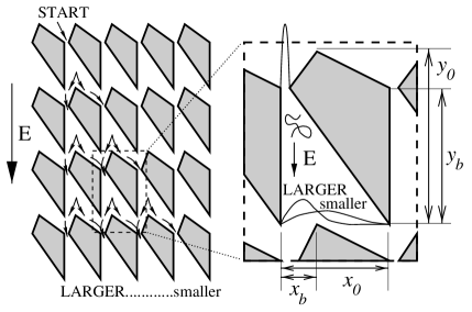
The geometry of the sieve is shown in Fig. 1. It consists of a rectangular array of “cells” of periodicity that have a narrow entrance at the top and two exits at the bottom, which connect to the next row of cells. DNA fragments, characterized by a persistence length , contour length , and diameter , enter from the top and move down the cell subject to an electric field . The radius of gyration and the self-diffusion constant of a DNA fragment of persistence lengths are given by
| (1) | |||||
| (2) |
where is the swelling exponent, is the diffusion constant for a single persistence length, and for the Rouse model[5] (free draining conditions) and for the Zimm model[6], where hydrodynamic interactions are taken into account[7]. The electrophoretic mobility of the fragments is independent of size and given by[8]
| (3) |
where and are the effective charge and friction coefficient of a persistence length of the DNA, respectively. (The Reynolds number is very small in all cases of interest, and inertial effects can be ignored.) Note that hydrodynamic interactions induced by Brownian Motion are not screened by counter-ions, as is the case of electrophoretic velocity fields[9, 10]. Consider a fragment that enters a cell at time and diffuses away from the left wall as it drifts down the cell. Ignoring its internal modes and characterizing its dynamics simply by its electrophoretic mobility and self-diffusion constant , the probability of finding the DNA a distance away from the left wall at time when it has drifted a distance from the top of the cell is given by
| (4) |
which can be obtained from the solution to the diffusion equation with reflective (Dirichlet) boundary conditions on the left wall, and ignoring the effect of the right wall. A branching point is located at a distance from the left wall and from the top of the cell. Fragments that have diffused farther from the left wall than the branching point are funneled to the entrance of the cell diagonal to the original one, whereas those that are closer to the wall end up at the entrance to the cell immediately below. The probability of branching can be calculated from Eq.(4) as
| (5) | |||||
| (6) |
For a DNA fragment of persistence lengths,
| (7) |
where
| (8) |
is the characteristic separation size of the sieve, and is a constant fitting parameter of . A remarkable observation is that can be tuned simply by changing the applied electric field, increasing the dynamic range of separation dramatically.
A more accurate analytical estimate of requires taking into account internal relaxation of the polymer, effective wall potentials at distances less than the radius of gyration of the polymer, corrections due to diffusion along the field direction, among other effects. For example, the right wall can no longer be ignored for , and the finite size of the fragment becomes significant when , or equivalently . Relaxation effects will be important when cell traversal time is less than the principal relaxation time , i. e., for . Computation of these effects is beyond the scope of this Letter. However, from a practical standpoint, characterization for a given geometry can be more readily achieved by numerical simulation or experiment for most applications, since completely characterizes the separational properties of the sieve and the periodic structure greatly simplifies the numerical determination of this quantity by simulating a single cell.
At this point, it is useful to point out that any sieve design that breaks the left-right symmetry can in principle be used for purposes of separation. The underlying idea is reminiscent of rachet potentials[11, 12], which have also been recently proposed as particle separators[13, 14]. Both rachets and the sieve exploit differences in diffusion constants and steric constraints, and if the axis is identified with time, the sieve can actually be thought of as the time history of a rachet potential. However, unlike rachets, the sieve does not require time dependent potentials and is able to operate in continuous mode.
Numerical integration of the equations of motion using the Rouse Model for polymers[5, 7] and reflecting boundary conditions at the walls is in good agreement with analytical results. Figure 2 shows how the probability density for the COM position of a polymer with evolves as it moves down the cell. After the initial internal relaxation time, the probability can be fitted to the form of Eq.(6); the inset shows the expected linear increase in the mean square distance from the left wall as a function of distance from the top of the cell. Figure 3 shows the branching probability as a function of polymer size, and has the expected exponential behavior, even though the sizes of the polymers become quite large compared to the cell feature size. A correlation analysis of the time series of branching events confirms that they are statistically independent from one cell to the next.


Although this method of separation sounds very promising in principle, it is important to assess performance parameters and feasibility before a decision can be made about its practicality and whether it can compete against established techniques for certain tasks. One of the most important issues is the resolution that can be achieved[15]. A monodisperse packet of polymers with size will spread laterally as it moves through the sieve, and after passing through rows, the density profile of te band will exhibit a Bernoulli distribution whose peak is located at and whose variance is [16]. Hence, the full width at half maximum (FWHM) of the corresponding band will be FWHM. On the other hand, the peak separation between polymers of sizes and in a polydisperse sample will increase as . Thus, resolution can be improved indefinitely by passing the polymers through more rows of cells. Optimal resolution is achieved when , for which rows are needed in order to resolve these two peaks. For a cell size of about 5 microns, up to rows should be feasible, enabling single-segment resolution up to and resolution beyond that. Note, however, that resolution can be further enhanced by gradient methods that are frequently implemented in gel electrophoresis[17], in this case by a spatially varying electric field or cell size.
Another major concern is the throughput, which is affected by various factors, including cross-sectional area, concentration and velocity of the polymers, and ease of specimen loading and extraction. Original electrolithographic designs proposed and tested by Austin and coworkers were extremely shallow[1, 18], with depths comparable to , in order to maximize hooking and to enable individual visualization of polymers. The sieve design presented here, on the other hand, will benefit from increased depth to at least , and the cells should be designed as deep as possible to increase throughput. A stacked configuration might be considered if the mechanical stability of posts becomes a concern. A major bottleneck is the entrance to the sieve, since all polymers should start from the same point, rather than a band, to achieve separation. This will give rise to significantly increased concentrations near the entrance to the sieve. Although a dilute solution is assumed in the calculation presented here, separation is not limited to the dilute regime and occurs in semidilute solutions as well. Since the mobility of polymers is significantly higher in the absence of a gel medium, much higher concentrations can be tolerated, therefore this bottleneck may not be as problematic as it appears. Furthermore, the easy and quick extraction of the separated specimens enables continuous operation, in which polymers are constantly added at the entrance and extracted from exit channels placed at the bottom of the sieve. Although the sieves might be expensive to produce, they are tunable and reusable, significantly lowering their effective cost. Thus, this technique may have major advantages over traditional methods for separation of large quantities.
The same technique can be applied to separation through centrifugation[3] as well. Individual sieves shaped as pie slices, with their entrances at the apex, can be arranged as stacked pies. The polydisperse solution can then be fed through a tube along the rotation axis and separated objects can be collected in containers around the circumference that rotate with the sieves. Virtually any separation characteristic can be achieved by modulating the cell size as a function of distance to the rotation axis.
The particular design presented here is only one possibility and is by no means an optimal geometry, although its performance is expected to be quite satisfactory. On the other hand, the scalable structure of the sieve makes it possible to fully characterize device performance from a detailed modeling of dynamics within a single cell, significantly simplifying a numerical design effort. Furthermore, technological requirements for an experimental realization is well within today’s capabilities, as has been demonstrated by Volkmuth et al.[1]. Therefore, experimental verification of the soundness of the general approach and a feasibility study of a prototype device is within reach in the very near future.
This research was supported by the National Science Foundation, by the MRSEC program through Grant No. DMR-9400396, and through Grants No. DMR-9106237, No. DMR-9417047, and No. DMR-9416910.
REFERENCES
- [1] W. D. Volkmuth and R. H. Austin, Nature 358, 600 (1992); W. D. Volkmuth et al., Phys. Rev. Lett. 72, 2117 (1994).
- [2] Ö. Gaál, G. A. Medgyesi and L. Vereczkey, Electrophoresis in the Separation of Biological Macromolecules (John Wiley and Sons, Chichester, 1980).
- [3] G. D. Birnie and D. Rickwood, eds., Centrifugal Separations in Molecular and Cell Biology (Butterworth & Co. Ltd., London, 1978).
- [4] K. Hannig, Z. Anal. Chem. 181, 244 (1961).
- [5] P. E. Rouse, J. Chem. Phys. 21, 1272 (1953).
- [6] B. H. Zimm, J. Chem. Phys. 24, 269 (1956).
- [7] M. Doi and S. F. Edwards, The Theory of Polymer Dynamics, (Oxford University Press, New York, 1986), pp. 91 – 103.
- [8] D. Long, J.-L. Viovy, and Armand Ajdari, Phys. Rev. Lett. 76, 3858 (1996).
- [9] W. B. Russel, D. A. Saville and W. R. Schowalter, Colloidal Dispersions (Cambridge University Press, Cambridge, UK, 1989), Chapter 7.
- [10] J. L. Barrat and J. F. Joanny, Adv. Chem. Phys. 94, 1 (1996).
- [11] P. Curie, J. Phys. III (Paris) 3, 393 (1984).
- [12] M. Magnasco, Phys. Rev. Lett. 71, 1477 (1993).
- [13] A. Ajdari and J. Prost, C. R. Acad. Sci. Paris 315, 1635 (1992).
- [14] G. W. Slater, H. L. Guo and G. I. Nixon, Phys, Rev. Lett 78, 1170 (1997).
- [15] L. S. Lerman and D. Sinha, in Electrophoresis of Large DNA Molecules – Theory and Applications, edited by E. Lai and B. W. Birren (Cold Spring Harbor Laboratory Press, Plainview, New York, 1990), pp. 1 – 8.
- [16] S. Chandrasekhar, Rev. Mod. Phys. 15, 1 (1943), Appendix I.
- [17] D. M. Hawcroft, Electrophoresis (Oxford University Press Inc., New York, 1997), p.26.
- [18] R. H. Austin et al., U.S. Patent No. 5,427,663 (1995).