Effect of Polarized Current on the Magnetic State of an Antiferromagnet
Abstract
We provide evidence for the effects of spin polarized current on a nanofabricated antiferromagnet incorporated into a spin-valve structure. Signatures of current-induced effects include bipolar steps in differential resistance, current-induced changes of exchange bias correlated with these steps, and deviations from the statistics expected for thermally activated switching of spin valves. We explain our observations by a combination of spin torque exerted on the interfacial antiferromagnetic moments, and electron-magnon scattering in antiferromagnet.
pacs:
73.40.-c, 75.50.Ee, 75.60.Jk, 75.70.CnPolarized current flowing through magnetic heterostructures can change the magnetic state of ferromagnets (F) due to the spin transfer (ST) effect cornellorig . It may find applications in magnetic memory devices, field sensors, and microwave generation. Despite advances in tunnel junction-based ST devices, their wide scale application is still deterred by the large power consumption. The efficiency of spin transfer into a nanomagnet F is determined by the threshold current for the onset of current-induced magnetic precession slonczewski96
| (1) |
at small external magnetic field . Here, is the electron charge, and are the magnetic moment and the volume of the nanomagnet, is the Gilbert damping parameter, and is a unitless parameter characterizing the efficiency of ST. is usually close to the current that reverses the magnetization of F.
According to Eq. 1, can be significantly reduced if F has a small magnetic moment . In nanopatterned magnets, a small compromises the magnetic stability of devices. However, more complex magnetic systems such as antiferromagnets (AF) can combine vanishing with a significant magnetic anisotropy, and may thus provide both stability and low operating power. Additionally, the possibility to change the magnetic structure of AF by current is attractive for devices utilizing AF for pinning the magnetization of the adjacent F, due to the exchange bias (EB) effect. ST in antiferromagnets has been predicted nunez , but experimental studies have been inconclusive ohno , emley , tsoiaf . Such studies may provide information about the role of electron-magnon scattering in ST phenomena, the nature of enhanced magnetic damping in F/AF bilayers damping , and the properties of the interfacial magnetic moments central to EB.
We report on the effect of polarized current on nanoscale AF elements incorporated in a giant magnetoresistive (MR) structure F1/N/F2/AF, with the top F2/AF bilayer patterned into an 12060 nm nanopillar. These samples are labeled EB nanopillars. Several important behaviors of our samples can be attributed to the effect of current on AF. First, EB an be changed by applying a pulse of current. The changes are non-monotonic and asymmetric with respect to the directions of current and applied field, which eliminates Joule heating as their origin. Second, the peaks in the current-induced EB are correlated with the onset of magnetic dynamics, indicating its importance for defining the magnetic state of AF. Finally, switching is inconsistent with the standard thermal activation model, indicating a complex current-induced magnetic state of AF.
We tested 8 samples with the structure Py(30)Cu(10)Py(5)Fe50Mn50(t)Cu(1)Au(10), where Py=Permalloy=Ni80Fe20, and . All thicknesses are in nanometers. Samples with exhibited complex reversal patterns and signatures of inhomogeneous magnetic states. We interpret these behaviors in terms of the local variations of exchange interaction at the F/AF interface. On the other hand, samples with exhibited the important features of EB associated with FeMn, while retaining single domain behaviors similarly to the samples not containing an AF layer (standard samples). The results reported below were verified for two EB samples with . Current flowed from the extended to the patterned Py layer, and was along the nanopillar easy axis.
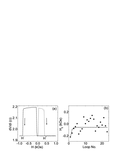
The MR of the EB sample shown in Fig. 1(a) was at , among the largest reported for metallic structures cornellorig , emley , myprl , cornellnature , krivorotov . The data were acquired immediately after cooldown at kOe from K. Field-induced reversals occurred in a single step at all temperatures between K and room temperature RT= K. Upward jumps of in Fig. 1(a) at small Oe are caused by the reversals of the extended Py(30) layer from the parallel (P) state of the Py layers into the antiparallel (AP) state. The asymmetric downward jumps at large and (labeled in Fig. 1(a)) are caused by the reversal of the patterned Py(5) layer. The asymmetry is due to FeMn, and can be characterized by the effective EB field Oe. The coercivity is Oe.
Very thin FeMn layers usually become magnetically unstable due to the reduced anisotropy energy nogues . Indeed, repeated cycling of yielded fluctuating values of (symbols in Fig. 1(b)). This behavior was attributed to reorientation of FeMn among a few metastable states. When similar measurements are performed in an extended film, should quickly decay from the initial value determined by the field cooling, due to the averaging of magnetic fluctuations over a large number of AF grains. This behavior was verified in a mm2 heterostructure Py(5)Cu(10)Py(5)FeMn(1.5)Cu(1)Au(3) magnetically identical to the EB nanopillars (curve in Fig. 1(b)).

The effect of current on the magnetic structure of AF can be determined by applying a pulse of current at field , and subsequently measuring the hysteresis loop at a small not affecting the magnetic state of the nanopillar. The results of such measurements are shown in Fig. 2 for kOe (a) and kOe (b). These values of suppressed current-induced reversal of the Py(5) nanopillar. The most prominent feature of the data is a sharp increase of up to a peak at mA, and a smaller peak at mA in Fig. 2(a), for kOe. The data in Fig. 2(b) for kOe are scattered, and do not exhibit a clear dependence on . If these changes of were caused by Joule heating of FeMn, the data in Figs. 2(a) and (b) would mirror each other, at least for large . Additionally, the effect of heating would increase with , so a monotonic dependence instead of peaks would be expected. Therefore, current must have a direct effect on the magnetic state of FeMn.
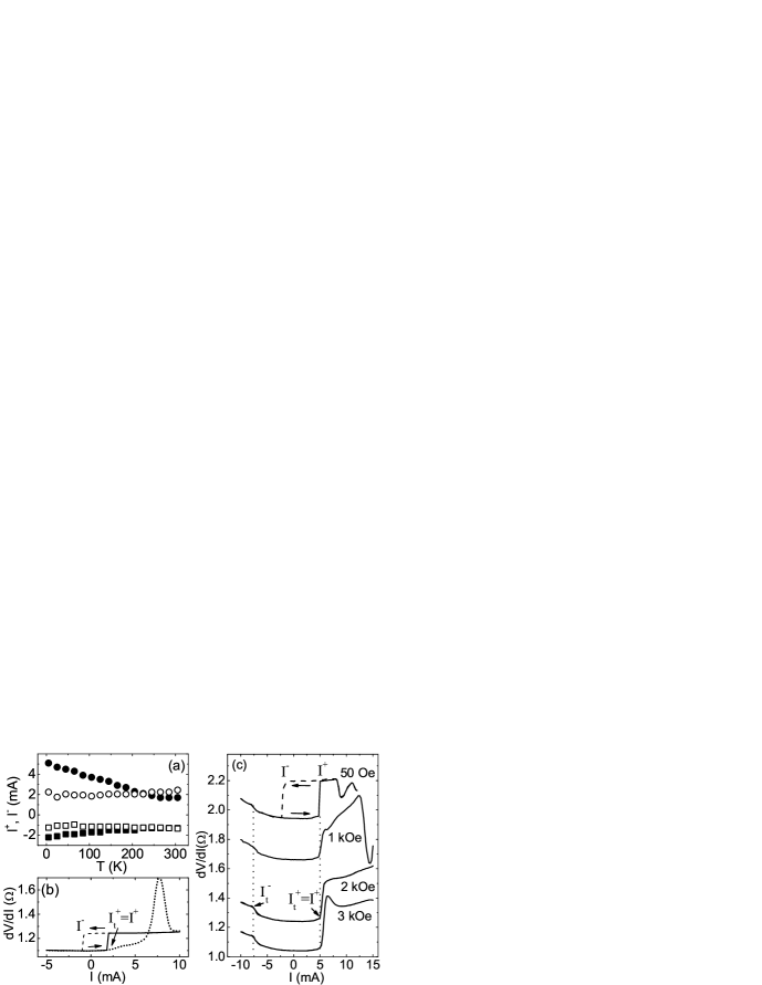
Additional evidence for the effects on FeMn distinct from Joule heating was provided by the measurements of current-induced behaviors. At small , Py(5) reversed into the P state at a current , and into the AP state at a current , consistent with the ST mechanism (top curve in Fig. 3(c)). However, the dependencies of and on reflected a strong influence of FeMn on the current-induced reversals. Fig. 3(a) shows that and in the standard sample did not significantly depend on (open symbols), but they increased linearly with decreasing in the EB nanopillars shunting . This result is consistent with the previously seen enhancement of magnetic damping due to AF emley , damping .
Current-induced behaviors of the EB samples were different from the standard ones at large , as shown in Figs. 3(b),(c). The standard sample exhibited two previously established features myprl . First, switching became reversible and exhibited telegraph noise, resulting in a peak in at (dotted curve in Fig. 3(b)). The peak rapidly shifted to higher at larger . The second feature was a weak increase of at . This feature is associated with the current-induced precession of the Py(5) magnetization cornellnature .
The EB nanopillars did not exhibit a reversible switching peak at any . The kOe data in Fig. 3(c) show a step at , and an approximately linear increase at until a drop at mA. At kOe and kOe, the step at is larger, and the increase of at higher is smaller. Because the position of the step does not significantly depend on , it can be attributed to the current-induced precession of Py(5), as confirmed by the time-resolved measurements described below. The step at is correlated with a peak of in Fig. 2(a). Similarly, a smaller step in at mA, labeled in Fig. 3(c), is also correlated with a peak of in Fig. 2(a) at . Both steps are attributed to the current-induced magnetic dynamics, which must therefore play an important role in current-induced EB. To confirm that these steps are associated with the FeMn layer, was increased to RT. Both steps disappeared, and the reversible switching peak was observed.
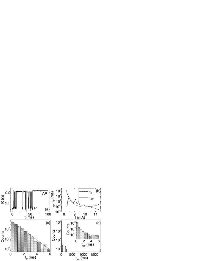
To identify the origin of the high-field current-induced behaviors in Fig. 3(c), we performed time-resolved measurements of resistance . Fig. 4(a) shows an example of a time trace acquired at mA and Oe. The data show telegraph noise switching between P and AP states, qualitatively similar to the standard sample. However, there are significant quantitative differences. First, the EB nanopillar occasionally spent a significant continuous period of time in the AP state, which was not observed in the standard samples. Second, the average dwell times in the P state () and the AP state () exhibited a nonmonotonic dependence on , as illustrated in Fig. 4(b) tauap . In contrast, the standard sample exhibited a monotonic increase of and a decrease of with increasing . The data for the standard sample were consistent with the Neel-Brown model of thermal magnetic activation zhang .
The dependencies of average dwell times on account for the approximately linear increase of at in the EB samples. The origin of these dependencies can be better understood by plotting the distributions of dwell times in the P state () and the AP state () (Figs. 4(c),(d)). closely followed an exponential distribution with a decay time ms at mA and Oe. Similar distributions were obtained for both and in the standard samples, consistently with the thermal activation model zhang . However, the distribution of for the EB nanopillar was clearly not exponential due to occasionally long dwell times in the AP state. Of the total sec time interval of data analyzed in Fig. 4(d), the system spent one continuous s long interval, and three ms long intervals in the AP state. The remaining dwell times were predominantly less than ms, as shown in the inset. As was increased, the intervals of long gradually disappeared, resulting in decreasing in Fig. 4(b). Simple enhancement of magnetic damping and/or the anisotropy induced by FeMn cannot account for the deviations from the standard exponential distributions. Therefore, this behavior is the strongest evidence in our data for the effect of on the magnetic state of FeMn, which results in occasional enhancement of Py(5) stability in the AP state.
Before discussing the mechanisms underlying the observed effects of current on the AF/F bilayer, we summarize the current-induced behaviors distinguishing the EB samples from the standard ones: i) The switching currents depend linearly on , ii) The effect of current on is asymmetric with respect to the directions of and , iii) Current-induced exhibits peaks correlated with the steps in , iv) Reversible switching exhibits occasionally long dwell times in the AP state.
We analyze our data using a model accounting for the contributions of both the spin current and the spin accumulation to ST at magnetic interfaces fert . The parameter in Eq. 1 characterizing ST at the interface N/F2 is expressed through the known material parameters
| (2) |
where is the current density, m/s is the average Fermi velocity in F2, and are the spin current density and spin accumulation density, respectively, just inside F2 at the N/F2 interface. Spin flipping in the Cu spacer is neglected in Eq. 2. The spin accumulation and spin current density were calculated self-consistently throughout the multilayer using the Valet-Fert model valetfert . Material parameters known from MR measurements and electron photoemission were used photoemission , gmr . Eq. 2 yielded for the P state, and for the AP state. Inserting those values into Eq. 1, we obtained good agreement with the switching currents at K by assuming . This value is in general agreement with for the standard samples krivorotov , and the enhancement of damping due to FeMn, as determined from the temperature dependence of switching currents (Fig. 3(a)).
A calculation for the Py/FeMn interface yielded a positive for the P state, implying that FeMn moments that are noncollinear to Py experience a spin torque favoring their parallel configuration with Py for , and antiparallel configuration for . Interfacial Mn moments tend to align antiparallel to the adjacent F, while Fe moments align parallel to it femn . The latter have a larger magnetic anisotropy and likely dominate the EB. The following picture of ST at the Py/FeMn interface then emerges. The positive value of at the Py/FeMn interface implies that ST acting on the interfacial Fe moments enhances EB for and suppresses it for , explaining the asymmetry with respect to the current direction in Fig. 2(a), for kOe. A step in at is likely caused by the current-induced precession of the stable Fe moments that remain antiparallel to the Py magnetization, consequently inducing dynamical Py response resulting in MR.
The asymmetric current-induced behaviors in Fig. 2(a) are superimposed on the symmetric enhancement of EB, independent of the current direction. We propose two possible mechanisms. First, electron-magnon scattering at the Py/FeMn interface may activate transitions of the FeMn magnetic moments into the stable orientation dictated by the magnetization of the adjacent Py. A second, probably weaker, effect may be due to a torque on the Fe moments exerted by the Oersted field of , assisting their rotation into the direction parallel to the Py moments. The peaks at and support the activation picture, since magnetic dynamics excited in FeMn either directly by ST, or indirectly through interaction with precessing Py, should assist in activating the transition of the AF magnetic moments into a stable configuration.
To interpret the lack of significant current dependence of EB on for the kOe data, we note that the average in Fig. 2(b) is independent of , and is similar but opposite in sign to the largest values obtained for kOe. Therefore, at kOe the system simply reverts to a stable configuration defined by the in-field cooldown. This state with higher anisotropy is not significantly affected by .
We also propose an interpretation for the non-exponential distribution of in Fig. 4(d). A simple enhancement of the AP state stability due to EB cannot be responsible, because then would also exhibit a similar effect. Therefore, the occasionally long are likely caused by the current-induced enhancement of magnetic stability, efficient only in the AP state at , but not in the P state. Since suppresses the fluctuations of the magnetic layer in the AP state, due to the ST in the standard samples zhang , a similar combined effect of current on both F and AF layers likely takes place in the EB samples. It is efficient only for some of the magnetic configurations that FeMn acquires due to the fluctuations, specifically those minimizing the current-induced precession of Fe moments, resulting only in occasional enhancement of .
In summary, we demonstrated that spin polarized electron current affects the magnetic state of an antiferromagnet. The effect is distinct from Joule heating, and is explained by a combination of a direct current-induced excitation of antiferromagnetic moments by spin transfer, and electron-magnon scattering at the magnetic interface. This mechanism may be useful for establishing exchange bias in nanoscale magnetoelectronic devices.
We acknowledge discussions with D. Lederman, K.-J. Lee, I. Moraru, N.O. Birge, and J. Bass.
References
- (1) J.A. Katine, F.J. Albert, R.A. Buhrman, E.B. Myers, and D.C. Ralph, Phys. Rev. Lett. 84, 3149 (2000).
- (2) J. Slonczewski, J. Magn. Magn. Mater. 159, L1 (1996).
- (3) A.S. Nunez, R.A. Duine, P. Haney, and A.H. MacDonald, Phys. Rev. B 73, 214426 (2006).
- (4) J. Hayakawa, H. Takahishi, K. Ito, M. Fujimori, S. Heike, T. Hashizume, M. Ichimura, S. Ikeda, and H. Ohno, J. Appl. Phys. 97, 114321 (2005).
- (5) N.C. Emley, I.N. Krivorotov, O. Ozatay, A.G.F. Garcia, J.C. Sankey, D.C. Ralph, and R.A. Buhrman, Phys. Rev. Lett. 96, 247204 (2006).
- (6) Z. Wei, A. Sharma, A.S. Nunez, P.M. Haney, R.A. Duine, J. Bass, A.H. MacDonald, and M. Tsoi, cond-mat/0606462.
- (7) J. Dubowik, F. Stobiecki, I. Goscianska, Y.P. Lee, A. Paetzold, and K. Roll, J. Kor. Phys. Soc. 45, 42 (2004).
- (8) S. Urazhdin, N.O. Birge, W.P. Pratt Jr., and J. Bass, Phys. Rev. Lett. 91, 146803 (2003).
- (9) S.I. Kiselev, J.C. Sankey, I.N. Krivorotov, N.C. Emley, R.J. Schoelkopf, R.A. Buhrman, and D.C. Ralph, Nature 425, 380 (2003).
- (10) I. N. Krivorotov, N. C. Emley, J. C. Sankey, S. I. Kiselev, D. C. Ralph, R. A. Buhrman, Science 307, 228 (2005).
- (11) J. Nogues and I.K. Schuller, J. Magn. Magn. Mater 192, 203 (1999).
- (12) The slight increase of , at is caused by the shunting currents through the Si substrate.
- (13) fluctuations of in Fig. 4(b) are caused by occasionally large discussed in the text.
- (14) Z. Li and S. Zhang, Phys. Rev. B 69, 134416 (2004).
- (15) A. Fert, V. Cros, J.-M. George, J. Grollier, H. Jaffres, A. Hamzic, A. Vaures, G. Faini, J. Ben Youssef, H. Le Gall, J. Magn. Magn. Mater. 272-276, 1706 (2004).
- (16) K.N. Altman, N. Gilman, J. Hayoz, R.F. Willis, F.J. Himpsel, Phys. Rev. Lett. 87, 137201 (2001).
- (17) J. Bass and W.P. Pratt, Jr., J. Magn. Magn. Mater. 200, 274 (1999).
- (18) W.J. Antel Jr., F. Perjeru, and G.R. Harp, Phys. Rev. Lett. 83, 1439 (1999); Offi, W. Kuch, L.I. Chelaru, K. Fukumoto, M. Kotsugu, and J. Kirschner, Phys. Rev. B 67, 094419 (2003).
- (19) T. Valet and A. Fert Phys. Rev. B 48, 7099 (1993).