Ground-state structure and stability of dipolar condensates in anisotropic traps
Abstract
We study the Hartree ground state of a dipolar condensate of atoms or molecules in an three-dimensional anisotropic geometry and at . We determine the stability of the condensate as a function of the aspect ratios of the trap frequencies and of the dipolar strength. We find numerically a rich phase space structure characterized by various structures of the ground-state density profile.
pacs:
03.75.HhI Introduction
The realization of Bose-Einstein condensation (BEC) in low-density atomic vapors bec1 ; bec2 has led to an explosion of experimental and theoretical research on the physics of quantum-degenerate atomic and molecular systems. While much of the work so far has concentrated on systems characterized by -wave two-body interactions, the recent demonstration of a condensate of chromium atoms chbec opens up the study of gases that interact via long-range, anisotropic magnetic dipole interactions. In a parallel development, it can be expected that quantum degenerate samples of heteronuclear polar molecules will soon be available through the use of Feshbach resonances Kett ; Jin1 , photoassociation DeM ; HetDeM1 , or a combination of the two. When in their vibrational ground state, these molecules interact primarily via the electric dipole potential, and they are expected to provide a fascinating new type dipole-dominated condensates in the near future.
As a result of the anisotropy and long-range nature of the dipole-dipole interaction, a number of novel phenomena have been predicted to occur in low-density quantum-degenerate dipolar atomic and molecular systems, both in conventional traps and in optical lattices. An early study of the ground state of polar condensates was presented in Ref. stabdp , which determined its stability diagram as a function of the number of atoms and -wave scattering length. It identified a stable structured ground state for a specific range of parameters. At about the same time, the effect of trap geometry on the stability of the condensate was considered in Ref. stabdp1 for a system dominated by the dipole interaction. This was followed by the prediction oplat of the existence of a number of quantum phases for dipolar bosons in optical lattices. Recent work dvor1 ; dvor2 considers the structural phases of vortex lattices in rotating dipolar Bose gases.
A novel feature of dipolar condensates, as compared to their scalar cousins, is the appearance of a roton minimum in their Bogoliubov spectrum. This feature was discussed in the context of atomic condensates in Ref. rotmax , which considered the impact of the roton-maxon feature in the excitation spectrum and the stability of pancake-shaped dipolar condensates. For this particular geometry it was found that the excitation spectrum can touch the zero-energy axis for a non-zero wave vector 2dd , which points to the instability of homogeneous condensates and the onset of density modulations sup . A roton minimum was also found odell1 for the case of laser-induced dipolar interactions in self-bound BECs with cylindrical symmetry. Quasi-2D dipolar bosons with a density-modulated order parameter were determined to be unstable within the mean-field theory coop , and cigar-shaped quasi-one dimensional condensates were likewise found odell to be dynamically unstable for dipoles polarized along the axis of the cylindrical trap. The stability of dipolar condensates in pancake traps was also recently discussed in Ref. stabdp2 , which found the appearance of biconcave condensates for certain values of the trap aspect ratio and strength of the dipole interaction. From the Bogoliubov excitation spectrum it was possible to attribute the instability of the condensate under a broad range of conditions to its azimuthal component.
Further building on these studies, the present note reports the results of a detailed numerical analysis of the stability and structure of the Hartree ground state of dipolar condensates confined in anisotropic harmonic trap. We proceed by introducing the trap frequencies and , respectively, in the , and directions, and the corresponding trap aspect ratios and . Thus corresponds to a pancake trap, whereas corresponds to a cylindrical trap with free motion in direction. We further assume for concreteness that an external field polarizes the dipoles along the axis. The stability of the condensate is then determined as a function of the trap aspect ratios and of an effective dipolar interaction strength that is proportional to the number of atoms or molecules in the condensate. Various ground state structures of the condensate are identified in the stable region of parameter space.
The remainder of this paper is organized as follows: Section II introduces our model and comments on important aspects of our numerical approach. Section III summarizes our results, identifying up to five different types of possible ground states, depending on the tightness of the trap and the particle number. Finally, Section IV is a summary and conclusion.
II Formal development
The dipole-dipole interaction between two particles separated by a distance is
| (1) |
where is the dipole-dipole interaction strength and is the polarization direction. For atoms with a permanent magnetic dipole moment we have while for dipolar molecules , and being the magnetic moment of the atoms and the electric dipole moment of the molecules, respectively.
Within the mean-field approximation, the condensate order parameter satisfies the Gross-Pitaevskii (GP) equation
| (2) | |||||
where
| (3) |
is the sum of the kinetic energy and the trapping potential and denotes the number of particles in the condensate. The second term on the right-hand side of Eq. (2) is the contact interaction, being proportional to the -wave scattering strength , and the third term describes the effects of the nonlocal dipole-dipole interaction. For dipole interaction dominated systems, is small compared to . This is the case that we consider here, and in the following we neglect the -wave scattering term altogether.
For convenience we introduce the dimensionless parameter
| (4) |
that measures the effective strength of the dipole-dipole interaction, where the oscillator length . The condensate ground state is then determined numerically by solving the Gross-Pitaevskii equation (2) for imaginary times. The term involving the dipole interaction energy is calculated using the convolution theorem,
where and stand for Fourier transform and inverse Fourier transform, respectively. The dipole-dipole interaction is calculated analytically in momentum space as stabdp ,
| (5) |
are the momentum components in direction.
The initial order parameter was chosen randomly, and the stability diagram was generated for each pair of parameters by increasing the effective dipolar strength until a critical value above which the condensate collapses. Because of the random initial condition this value varies slightly from run to run. The plotted results show the average over 100 realizations of the initial wave function, the error bars indicating the maximum deviation from of from its mean . This approach typically resulted in numerical uncertainties similar to those of Ref. dip .
III results
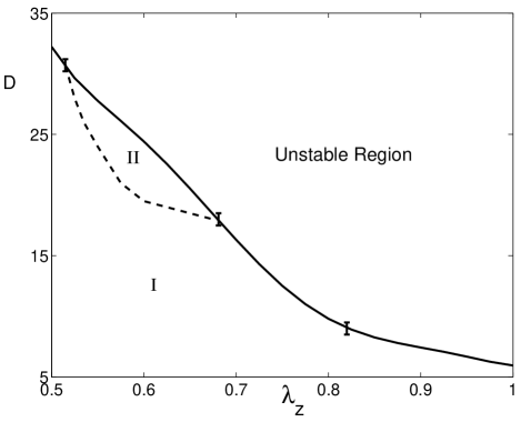
A good starting point for the discussion of our results is the observation that in the case of a cylindrical trap, , we found no stable structured condensate ground state. (By structured profiles, we mean profiles that are not simple gaussians.) In particular, solutions exhibiting density modulations along the -axis were found to be unstable. Moving then to the case of a pancake trap by keeping fixed but increasing from to , we found for the appearance of a small parameter region where the stable ground state is characterized by a structured density profile, the domain of stability of this structured solution increasing with . A phase space stability diagram typical of this regime is shown in Fig. 1 for . In this figure, region is characterized by the existence of a usual condensate with its familiar, structureless gaussian-like density profile. As is increased, the condensate becomes unstable for decreasing values of the effective dipole interaction strength , or alternatively of the particle number . For , though, the ground state changes from a gaussian-shaped to a double-peaked density profile (domain II in the figure), before the system becomes unstable.
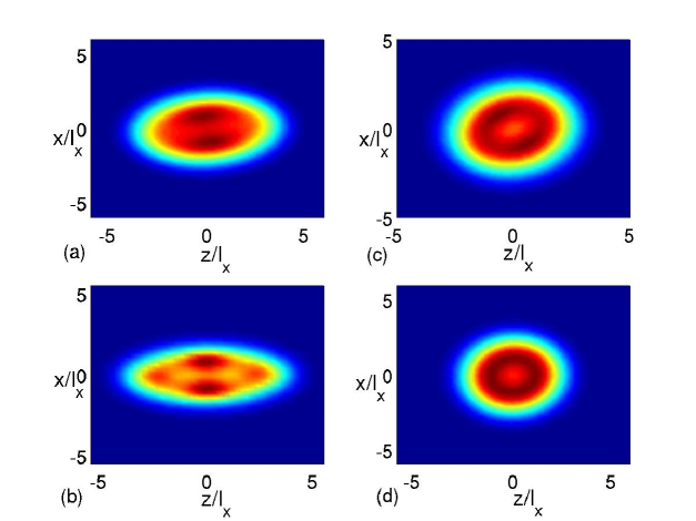
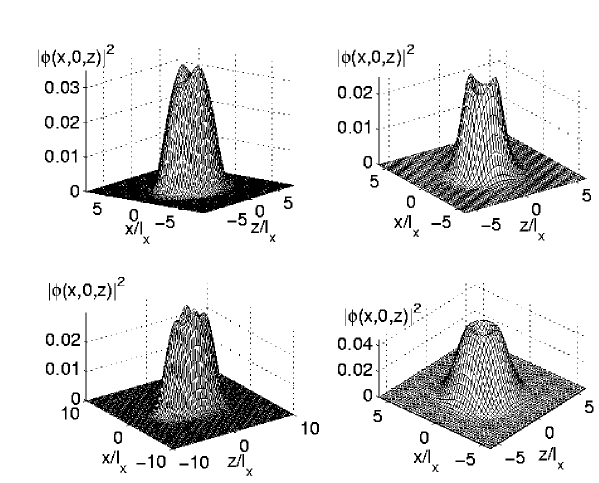
Figures 4 and 5 show surface plots and corresponding 3-D renditions of density profiles typical of the various situations encountered in our study. Figures 4a and 5a are illustrative of the present case. The appearance of two density peaks away from the center of the trap results from the interplay between the repulsive nature of the dipoles in a plane transverse to its polarization direction, the plane, and the confining potential.
Increasing the tightness of the trap along the polarization direction , i.e, increasing , results in the emergence of additional types of structured ground states. One such case is illustrated in Fig. 2, which is for . For small values of , i.e., a weak trapping potential along the -direction, we observe the appearance of a domain (region III in the figure) characterized by a double-peaked ground state with the maximum density along the direction and a gaussian-like density in direction. This type of double-peaked structure along the weak trapping axis was first predicted in Ref. dpeak . Typical density profiles in this region resemble those in Figs. 4a and 5a, but with a rotation by 90 degrees in the -plane. The regions II and III are separated by a small additional domain IV characterized by a ground-state distribution with a quadruple-peaked structure as illustrated in Figs. 4b and 5b, as might be expected. In general, these characteristics of the ground state density profile persist until .
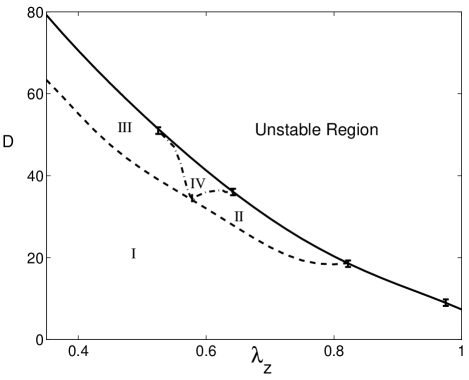
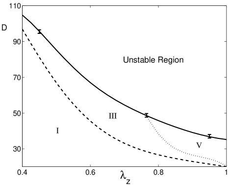
Figure 3 shows a stability diagram typical of higher values of the aspect ratio , in this case , for . As is increased, the ground-state density of the condensate first undergoes a transition from a gaussian-like to a double-peaked profile of the type illustrated in Figs. 4b and 5b (region III). As is further increased, this domain is followed for close enough to unity by a second transition to a domain (region V) with the appearance of a density minimum near trap center. Initially, this minimum is surrounded by a region with a radial density modulation, see Fig. 4c, but for larger values of this modulation is reduced, see Figs. 4d and 5d. In that region, the density profile resembles the solution previously reported in Ref. stabdp2 for a similar parameter range.
.
In the case of atoms a typical magnetic moment of , and we find that the range of critical dipole strengths corresponding to structured ground states can be achieved for atoms for trapping frequencies . For molecules with a typical electric dipole moment of the corresponding number is molecules. While these are relatively high particle numbers, especially for the atomic case, they do not seem out of reach of experimental realization.
IV conclusion
In conclusion, we have performed a detailed numerical study of the ground state structure and stability of ultracold dipolar bosons in an anisotropic trap for dipoles polarized along the -direction. The trap aspect ratios along and direction, and were used as control parameters, and the mean-field stability diagram has established as function of these parameters and a dimensionless interaction strength . For small the system was found to exhibit a standard density profile, but for larger values, and depending on , various structured ground state were found to appear before reaching the unstable regime where the condensate collapses. These include a four-peak structured solution in the plane, a ring-like ground state with a modulated radial density profile. For and , we found a biconcave condensate profile, as already reported in stabdp2 .
For strong confining potentials along the dipole polarization direction, i.e for large , increasing can be viewed as resulting in a change from a quasi-one dimensional to a quasi-two-dimensional geometry. As such we can think of the various ground-state structures as a result of dimensional crossover in a trapping geometry. To gain a deeper understanding of these structures as we approach the instability region, future work study the Bogoliubov spectrum of the trapped system.
Acknowledgements.
We thank Drs. D. O’Dell, D. Meiser and R. Kanamoto for numerous useful discussions and comments. This work is supported in part by the US Office of Naval Research, by the National Science Foundation, by the US Army Research Office, by the Joint Services Optics Program, and by the National Aeronautics and Space Administration.References
- (1) M. J. Anderson et al., Science 269, 198 (1995).
- (2) K. B. Davis et al., Phys. Rev. Lett. 75, 3969 (1995).
- (3) A. Griesmaier et al., Phys. Rev. Lett. 94, 160401 (2005).
- (4) C. A. Stan, et al., Phys. Rev. Lett. 93, 143001 (2004).
- (5) S. Inouye, et al., Phys. Rev. Lett. 93, 183201 (2004).
- (6) A. J. Kerman, et al., Phys. Rev. Lett. 92, 033004 (2004).
- (7) J. M. Sage, S. Sainis, T. Bergeman, and David DeMille, Phys. Rev. Lett. 94, 203001 (2005).
- (8) K. Góral, K. Rza¸żewski and T. Pfau, Phys. Rev. A 61, 051601(R) (2000) .
- (9) L. Santos, G. V. Shlyapnikov, P. Zoller, and M. Lewenstein, Phys. Rev. Lett. 85, 1791 (2000).
- (10) K. Góral, L. Santos and M. Lewenstein, Phys. Rev. Lett. 88, 170406 (2002) .
- (11) N. R. Cooper, E. H. Rezayi, and S. H. Simon, Phys. Rev. Lett. 95, 200402 (2005).
- (12) J. Zhang and H. Zhai, Phys. Rev. Lett. 95, 200403 (2005).
- (13) L. Santos, G. V. Shlyapnikov and M. Lewenstein, Phys. Rev. Lett. 90, 250403 (2003).
- (14) U. R. Fischer, Phys. Rev. A 73, 031602(R) (2006).
- (15) Y. Pomeau and S. Rica, Phys. Rev. Lett. 72, 2426 (1994).
- (16) D. H. J. O’Dell, S. Giovanazzi, and G. Kurizki, Phys. Rev. Lett. 90, 110402 (2003).
- (17) S. Komineas and N.R. Cooper, cond-mat/0610702.
- (18) S. Giovanazzi and D. H. J. O’Dell, Eur. Phys. J. D 31, 439 (2004).
- (19) S. Ronen, D. C. E. Bortolotti, and J. L. Bohn, Phys. Rev. A 74, 013623 (2006).
- (20) T. F. Jiang and W. C. Su, Phys. Rev. A 74, 063602 (2006)
- (21) S. Ronen, D. C. E. Bortolotti, and J. L. Bohn, Phys. Rev. Lett. 98, 030406 (2007).