Discontinuous Meniscus Location in Tapered Capillaries Driven by Pressure Difference and Dielectrophoretic Forces
Abstract
We calculate the meniscus location in tapered capillaries under the influence of pressure difference and dielectrophoretic forces with and without gravity. We find that the meniscus location can be a discontinuous function of the pressure difference or the applied voltage and that the meniscus can “jump” to one end or another of the capillary. Phase diagrams are given as a function of the pressure and voltage, depending on the geometrical parameters of the system. We further consider a revision of the dielectric rise under dielectrophoretic force in wedge capillaries and in the case of electrowetting, where the dielectrophoretic force is a small perturbation. Finally, we also find discontinuous liquid–gas interface location in the case of liquid penetration into closed volumes.
I 1. Introduction
The location of the interface between two immiscible liquids or between a liquid and a gas is essential in microfluidic applications since the meniscus determines the way light is scattered beebe ; whitesides ; quake , how chemical species interact manz ; demello , the way drops are transported in small channels pgg_b_q ; pgg_rmp , and so forth. Attention must be given to liquid channels or capillaries where the cross-section is nonuniform, since liquid channels are never perfectly uniform and, as we show below, this nonuniformity has a strong effect on the meniscus location tbj1 ; SB ; tsori_langmuir2006 .
Consider a liquid contained in a channel with hard walls and a varying cross section, and suppose that there is a pressure difference between the two sides of the meniscus. At first glance, it seems that an increase in will cause the meniscus to move to the point where the Laplace pressure, as determined from the local geometry, equals , so the meniscus location as a function of is continuous if the channel is smooth. When a dielectrophoretic force or, indeed, a gravitational force, is acting on the liquid at the same time, we find that this naive picture is changed and that the meniscus location becomes a discontinuous function of . The current case is different from those of refs SB ; parry1 in that (i) it takes into account gravity and electrostatic forces, (ii) pressure differences exist even for a flat interface due to an external “pumping”, and (iii) the liquid layer is found underneath the solid surface and acts as a big reservoir.

To be concrete, we consider the illustration in Figure 1. A similar wedge-shaped geometry has recently been investigated on homogeneous (miscible) mixtures TTLnature ; TLpre . Here, the meniscus can be a liquid–gas or liquid–liquid interface, and its location is given by (being negative in part a and positive in part b). The distance between the tilted planes at is , and is the tilt angle. In regular capillary rise, is positive if the wetting angle is smaller than and is negative if . In addition to the gravitational forces and the pressure difference, a dielectrophoretic force is acting: a high-frequency voltage difference is imposed across the two tilted planes. The frequency is assumed to be high enough so ionic screening does not occur, and the force exerted on the liquid is dielectrophoretic in nature.
We restrict ourselves to narrow capillaries, where is satisfied, where is the capillary length ( is the interfacial tension, and is the density difference between the two liquids). In this case, as will be verified below, the height is larger than the radius, , and the height variations of the meniscus surface are negligible compared to the total height. In mechanical equilibrium, at the contact line, the Laplace pressure is balanced by the hydrostatic pressure
| (1) |
where is the pressure difference and is the inverse curvature given by . Here, is the surface separation at the meniscus’ location and is given by . The height-dependent electric field is TLpre
| (2) |
Finally, is the permittivity difference between the liquid and the gas or between the two liquids.
The electric field has two general effects: (i) it exerts a net dielectrophoretic body force on the liquid and (ii) it changes the contact angle. The exact influence of the electric field thus depends on the applied frequency tbj2 ; tbj3 . Unless otherwise stated, we will deal with the high-frequency regime, where the electric field is dielectrophoretic in nature, and the contact angle is unaffected by the field. Equation 1 is the basic relation for the meniscus location, and it will be studied in detail for several cases below.
II 2. No Gravitational Force
The gravitational force is zero if the channel is horizontal, as occurs in many cases, or if is sufficiently small. In this case, we are faced with the following equation:
| (3) |
Note that if is zero, there is a balance of the dielectrophoretic force against the surface tension, and this leads to some liquid height where the forces balance. in this case is a continuous function of the system parameters (e.g., ). Since this is the less interesting scenario, we now assume, without loss of generality, that . We obtain the following for the mechanical balance:
| (4) |
This relation can be further cast in the dimensionless form:
| (5) |
where
| (6) |
and the dimensionless numbers are
| (7) |
Let us look at the magnitude of and . For a pressure difference atm, surface tension N/m, and mm, we find . If (where is the vacuum permittivity) and V, we find . Thus, can be very large while is typically quite small, and the product is .
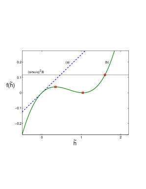
Equation 5 is a parabola in the variable , and is always positive, because . Let us look at the case of positive and but negative ; this means that the dielectric liquid is pulled toward higher values of by the electric field and applied pressure. The minimum of the parabola is at .
If or is sufficiently small, there are two roots to the equation: an unstable one and a stable root (see Figure 2a). Figure 2b shows as a function of the product at given and values. There is no solution if or is too large, and this occurs when , where
| (8) |
is a critical value of . Hence, an increase of from below to above leads to a jump of the meniscus from given by
| (9) |
to the top of the capillary. Relation 8 can be inverted to give a condition for a critical angle :
| (10) |
The meniscus location is changing continuously for and is found at the capillary’s top when .
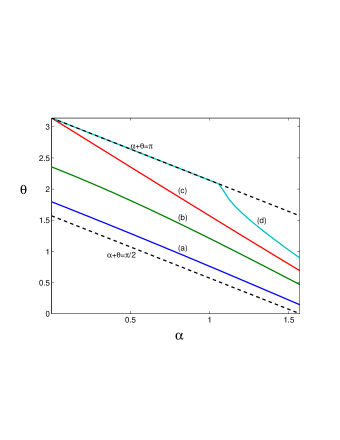
The phase diagram is presented in Figure 3 as a function of and for different values of . As the value of increases from zero, the area below the lines (solid curves) increases. This area is where the meniscus is found at the top of the liquid channel, while above it the meniscus location is continuous. Lines (a) and (b) are for and , respectively. Curve (c) corresponds to , and it is the first that touches the limiting diagonal line . As increases above , the line overlaps with the line for small values of but not for large ones (curve (d) for ). The maximum value of occurs at . Therefore, from eq 8, we see that there is another special value of :
| (11) |
Hence, when the meniscus is at the top for all values of and .
In the following section, we investigate the case of a tapered liquid channel under a gravitational force in addition to the dielectrophoretic force but in the absence of pressure difference.
III 3. Gravity Effect in the Absence of Pressure Difference
We now turn to the rather complex case where there are dielectrophoretic and interfacial tension forces acting, together with gravity, but no pressure difference. The governing equation reads as follows:
| (12) |
The high-frequency limit of the potential corresponds to the purely dielectrophoretic case, where is simply the zero-field contact angle. In the low-frequency limit, , the dielectrophoretic force vanishes (this is equivalent to setting above), while is the voltage-dependent (Lipmann) contact angle.
The gravitational force introduces the capillary length , and this length is used to scale all lengths in the system. The above equation can be expressed using dimensionless lengths as follows:
| (13) | |||||
where
| (14) |
To investigate the field effect, we note that is usually small and seek solutions with . In the absence of an electric field (), eq 13 was recently studied in ref. tsori_langmuir2006 , and we give here a brief summary of the main results. We rewrite eq 13 without the -dependent terms as follows:
| (15) |
has a maximum at , and its value at the maximum is . Thus, for hydrophilic surfaces (), for small and negative values, there is a solution to eq 15. If is too large, however, there is no solution: is smaller than , and the meniscus jumps from
| (16) |
to the capillary’s end (to the top if and to the bottom if ). The condition for the meniscus’ jump is as follows:
| (17) |
Alternatively, the condition can be expressed as a condition for a critical angle :
| (18) |
For a negative angle , the meniscus location is continuous if , while the meniscus is at the top for every . The system is invariant with respect to the transformation and . Hence, for a positive value of , if , the meniscus is at the capillary’s bottom, and its location is continuously changing for . There is a “special” angle given by . If , the meniscus location as a function of is continuous for all values.
We now add the field’s effect and treat eq 13 perturbatively with small values. We are looking for the maximum of from eq 13. Using , we find that
| (19) |
To first order in , the relation replacing eq 17 is
| (20) |
Note that, in the preceding derivation, the second term on the right-hand side was assumed to be small compared with the first term. However, as approaches , the first term goes to zero, while is finite: in this limit, the dielectrophoretic term dominates and does not represent a small correction anymore, and our derivation fails.
The condition for the critical angle becomes
| (21) |
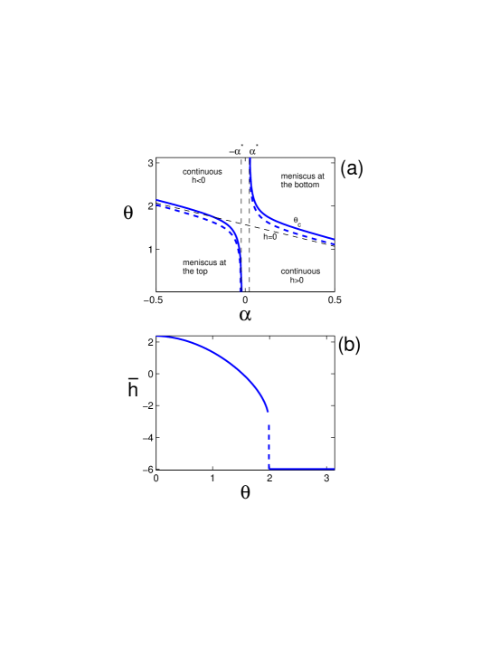
Figure 4 summarizes these findings. The zero-field critical value of is shown as dashed lines in Figure 4a, while the solid lines represent the critical angle for the case where . At a positive value, if , the meniscus location is continuously changing with . Below the diagonal dashed line , is positive, while above the dashed line. Above the , line the meniscus is at the capillary’s bottom. Note that the electric field breaks the symmetry of the system: while basically similar behavior appears at negative values of , the operation and does not leave the system invariant as it does for the case.
IV 4. Revision of the Problem of Dielectric Rise
We now consider the case of a liquid dielectric rise in tapered capacitors. We assume that the interfacial tension is negligibly small and that there are no imposed pressure differences: . The first treatment to this problem was given by T. B. Jones in a classical paper from 1974 tbj1 . The hydrostatic pressure is balanced by the dielectrophoretic force, yielding
| (22) |
Or, expressed differently,
| (23) |
where the dimensionless quantities are
| (24) |
and is given by
| (25) |
The difference between our derivation and the one by Jones is the expression for the electric field (eq 2), which is more accurate for large angles (); however, in the limit , we expect to recover Jones’ results. In the more usual case of a nontapered capillary (), we recover the familiar expression
| (26) |
which is equivalent to
| (27) |
in physical quantities.
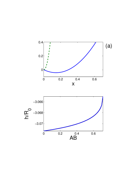
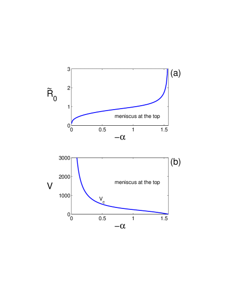
Let us concentrate on the case where . As is seen in Figure 5, has an inflection point. There are two extrema located at
| (28) |
Both extrema are positive and smaller than the maximum height in the capillary, . The value of at these extrema is
| (29) |
The left-hand side of eq 23 represents a horizontal line, and it can cross at the right or left branch. On increasing from zero, the solution jumps from the right branch to the left one when , that is, when
| (30) |
Alternatively, for the critical voltage , we find the following expression:
| (31) |
Figure 6a shows the phase diagram for the meniscus location. The solid line is from eq 30. At a given negative value of , if is below the critical line, the meniscus is at the top of the capillary, while above this line the meniscus location is continuous. Figure 6b expresses this behavior in the – plane. As is increased above given by eq 31, the meniscus jumps to the capillary’s top. The meniscus location is continuous below it.
In the following section, we find that similarities appear for a liquid channel blocked at one end, because in this case the pressure difference depends on the meniscus location.
V 5. Liquid Penetration into Closed Volumes
In this section, we turn to describing the meniscus location in tapered channels where one of the ends is blocked. The interface is a gas–liquid interface, as depicted in Figure 7. In the following, we assume that gravity and electric fields are absent, but nonetheless we find that the meniscus location can be discontinuous. The reason for this is the nonlinear dependence of the gas pressure in the area enclosed by the liquid and the walls on the gas volume, and the gas pressure must be balanced by the Laplace pressure.
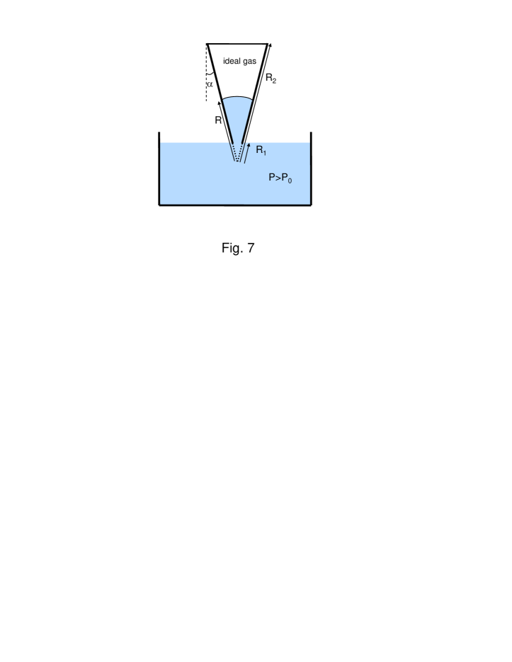
The liquid channel is wedge-shaped, with large and small opening radii and , as measured from the imaginary meeting point of the channel walls, and the opening angle is , as defined in Figure 7. Let us call and the gas volume and pressure, respectively, just before contact of the liquid channel with the liquid reservoir; is also the ambient pressure in the liquid. The channel is then brought in contact with the liquid, the liquid pressure is increased by an amount , and the liquid may penetrate to a distance inside the capillary. It follows from simple geometry that the maximum gas volume (i.e., when ) is
| (32) |
where is its depth in the third dimension (in the page). The total gas volume for is
| (33) |
Assuming the ideal gas law , we find that the gas pressure is
| (34) |
The outside pressure is increased to . We continue in the limit of the very small channel opening, that is, and , and therefore, eq 3 with leads to
| (35) |
This governing equation can be written using the dimensionless variables
| (36) |
in the following form:
| (37) | |||||
At this point, we would like to remind the reader that if the ambient pressure is atmospheric, Pa, it follows that , where we took N/m and cm. In the following, we will concentrate on ; however, we will assume .
We seek the meniscus location for a given pressure difference and for hydrophobic channels. This means that we seek the solution of eq 37 for fixed , negative , and increasing . is nonnegative and smaller than , and the function descends for small values and ascends for larger values. The minimum of is obtained at given by
| (38) |
and the value at the minimum is . When , the meniscus is at ; that is the liquid does not penetrate into the closed volume. If , then the meniscus is at , as is given by a direct solution of eq 37. The meniscus jumps from to when . This can be expressed by the rather long expression
| (39) |
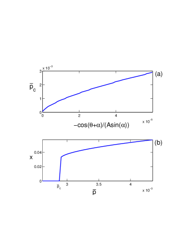
As we mentioned above, we are interested in the limit , and in this case, we can obtain the following approximate and much simpler expression for the critical value of the dimensionless pressure :
| (40) |
As is increased from zero to , the meniscus jumps from to , where is given by:
| (41) |
Figure 8a shows as a function of increasing as given by eq 40. if , and increases monotonically with . Figure 8b shows the scaled meniscus location as a function of at a given value of . As is increased from zero, jumps from to at and increases monotonically with a further increase in .
We would like to stress that one can also ask the following question: at what value of interfacial tension does the meniscus jump for a given value of ? The expression for as a function of is obtained directly from the inversion of eq 40. In addition, we recall that the ideal gas pressure is given by , where is the gas density, is the Boltzmann constant, and is the absolute temperature. We thus point out that one can hold both and constant while changing the temperature. Again, eq 40 can be used to find a critical temperature for the meniscus jump.
VI 6. Conclusions
In this article, we consider in detail the location of a liquid–liquid or liquid–gas interface in tapered capillaries. The driving forces are external pressure difference, interfacial tension, and electrostatic and gravitational forces.
As one would naively expect, a small change in the external forces usually leads to a small change in the equilibrium interface location. However, as is shown above without exception, due to the nonlinearity of the competing forces, there are critical values of the external parameters: pressure, wetting angle, voltage, and so forth. If the external force is close to its critical value, the equilibrium interface location is discontinuous. This is a rather general phenomenon in capillaries with nonuniform cross-sections, and occurs even at small “opening angles” . In section 2, we considered a capillary with a pressure difference and dielectrophoretic forces and obtained the threshold values of applied voltage or pressure difference to drive the meniscus location discontinuity. In section 3, we studied the liquid rise in capillaries under a weak dielectrophoretic force and gravity. The meniscus jump was discussed in terms of the wetting angle and wedge opening angle . We further looked in section 4 at the classical problem of dielectric rise, but this time in a tapered capacitor. Again, we found that the meniscus location exhibits discontinuities as a function of applied voltage or the geometrical parameters. Finally, in section 5, we considered liquid penetration into closed volumes and once more found a similar transition for the meniscus location as a function of the external driving forces.
The rich behavior found above is certainly relevant to several microfluidic systems, where the control of the liquid–gas or liquid–liquid interface at the small scale is important. A generalization which fully takes into account the frequency dependence of electric fields is a natural extension of the current work and should be explored tbj2 ; tbj3 , especially in the context of microfluidic systems.
VII Acknowledgments
I am indebted to F. Brochard-Wyart and P. -G. de Gennes, with whom I had numerous fruitful discussions and correspondences on the subject. For stimulating comments, I would like to thank A. Marmur and T. B. Jones. This research was supported by the Israel Science Foundation (ISF) Grant No. 284/05.
References
- (1) Beebe, D. J.; Atencia, J. Nature 2005, 437, 648.
- (2) Whitesides, G. M. Nature 2006, 442, 368.
- (3) Psaltis, D.; Quake, S. R.; Yang, C. Nature 2006, 442, 381.
- (4) Janasek, D.; Franzke, J.; Manz, A. Nature 2006, 442, 374.
- (5) deMello, A. J. Nature 2006, 442, 394.
- (6) de Gennes, P. G.; Brochard-Wyart, F.; Quéré, D. Gouttes, bulles, perles et ondes; Belin: 2002 (Paris).
- (7) de Gennes, P. G. Rev. Mod. Phys. 1985, 57, 827.
- (8) Jones, T. B. J. Appl. Phys. 1974, 45, 1487.
- (9) Shuttleworth, R.; Bailey, G. L. J. Discuss. Faraday Soc. 1948, 3, 16.
- (10) Tsori, Y. Langmuir 2006, 22, 8860.
- (11) Parry, A. O.; Wood, A. J.; Rascon, C. J. Phys.: Condens. Matter 2001, 13, 4591.
- (12) Tsori, Y.; Tournilhac, F.; Leibler, L. Nature 2004, 430, 544.
- (13) Tsori, Y.; Leibler, L. Phys. Rev. E. 2005, 71, 032101.
- (14) Jones, T. B. Langmuir 2002, 18, 4437.
- (15) Jones, T. B.; Wang, K.-L.; Yao, D.-J. Langmuir 2004, 20, 2813.