Charge Order and the Origin of Giant Magnetocapacitance in LuFe2O4
Abstract
The nature of the charge order in the charge frustrated compound LuFe2O4 and its effect on magnetocapacitance were examined on the basis of first-principles electronic structure calculations and Monte Carlo simulations of electrostatic energy. Our work shows that two different types of charge order of almost equal stability (i.e., and chain types) occur in the Fe2O4 layers of LuFe2O4, and that the ground state of LuFe2O4 has a ferrielectric arrangement of the Fe2O4 layers with charge order. The giant magnetocapacitance effect of LuFe2O4 at room temperature is accounted for in terms of charge fluctuations arising from the interconversion between the two types of charge order, that becomes hindered by an applied magnetic field.
pacs:
71.20.-b,71.45.Lr,77.80.-e,77.84.-sFerroelectric (FE) oxides are essential components in a large number of applications Auciello1998 . In traditional FE materials like BaTiO3, the ferroelectricity is driven by the hybridization of the empty d orbitals of Ti4+ with the occupied p orbitals of the oxygen anions Cohen1992 . Recently, a mixed-valence compound LuFe2O4 with the average valence Fe2.5+ was found to exhibit ferroelectricity associated with the charge order (CO) leading to Fe2+ and Fe3+ ions Ikeda2005 . Subramanian et al. reported that at room temperature (RT) the dielectric constant of LuFe2O4 decreases sharply when a small magnetic field is applied Subramanian2006 . This suggests a strong coupling between spin moment and electric dipole at RT, and hence potential applications of LuFe2O4 in which the charge and spin degrees of freedom of electrons can be controlled.
At RT LuFe2O4 has a hexagonal layered structure (space group R3̄m, a = 3.44 Å, and c = 25.28 Å) in which all Fe sites are crystallographically equivalent Isobe . LuFe2O4 is an insulator Tanaka , and undergoes a three-dimensional CO below 330 K Isobe ; LuFe2O4 ; RFe2O4 as well as a two-dimensional ferrimagnetic order below 240 K RFe2O4 . In LuFe2O4, layers of composition Fe2O4 alternate with layers of Lu3+ ions, and there are three Fe2O4 layers per unit cell (Fig. 1(a)). Each Fe2O4 layer (referred to as the W-layer) is made up of two triangular sheets of corner-sharing FeO5 trigonal bipyramids (Fig. 1(b)-(d)).
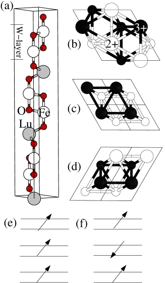
LuFe2O4 exhibits apparently puzzling physical properties, and the nature of its CO is not unequivocal. It is generally believed that lattice distortions accompany a CO Wright2001 . Thus, it is unclear why LuFe2O4 is insulating above RT despite that LuFe2O4 adopts the structure in which all Fe sites are equivalent in this temperature region. The giant magnetocapacitance effect found for LuFe2O4 can be understood by supposing that the charge fluctuation (CF) of LuFe2O4 arising from its charge frustration is sharply reduced by an external magnetic field. However, it is unclear by what mechanism this happens. As to the nature of the CO in LuFe2O4, there is a controversy. By analogy with the stable long-range order of Ising spins in a triangular lattice antiferromagnet (TLA), Yamada et al. proposed a model CO structure in which the two triangular sheets of a W-layer do not have the same number of Fe2+ and Fe3+ ions, i.e., [Fe2+]:[Fe3+] = 1:2 in one triangular sheet, and 2:1 in another triangular sheet (i.e., the CO-I structure in Fig. 1(b)) Yamada1997 . The superstructure of this CO model is compatible with the experimental observation. Subramanian et al. proposed a different CO structure in which one triangular sheet of a W-layer has only Fe2+ ions and the other triangular sheet has only Fe3+ ions (i.e., the CO-II structure in Fig. 1(c)) Subramanian2006 , on the basis of the fact that the closest Fe-Fe distances in LuFe2O4 occur between adjacent triangular sheets of a W-layer rather than within each triangular sheet.
In this Letter, we probe the nature of the CO and the origin of the magnetocapacitance in LuFe2O4 on the basis of first principles electronic structure calculations and Monte Carlo (MC) simulations of electrostatic interactions. Our study shows that the ground state of LuFe2O4 has the CO-I structure, the CO-II structure is unstable, and another CO structure different from CO-I and CO-II is very close in energy to the CO-I structure. The presence of two different CO structures close in energy is found crucial for the magnetocapacitance effect of LuFe2O4.
Our spin-polarized density functional theory calculations were performed on the basis of the frozen-core projector augmented wave method PAW encoded in the Vienna ab initio simulation package VASP using the generalized-gradient approximation (GGA) Perdew1996 and the plane-wave cut-off energy of 400 eV. To properly describe the strong electron correlation in the 3d transition-metal oxide, the GGA plus on-site repulsion U method (GGA+U) was employed Dudarev1998 with the effective value ( ) of 4.61 eV. Calculations with various values show that our main results remain valid when is varied between 3.6 and 5.6 eV. In the following we report only those results based on eV. To simplify our discussion and reduce the computational task, we explore the CO structures of LuFe2O4 under the assumption that the spins of LuFe2O4 have a ferromagnetic (FM) ordering. This assumption is reasonable because the energy scale associated with different spin arrangements is much smaller than that associated with different CO’s. An additional restriction of our calculations is the use of the experimental lattice constants. Our full geometry optimization of LuFe2O4 with GGA calculations leads to the lattice constants that are very close to the experimental values.
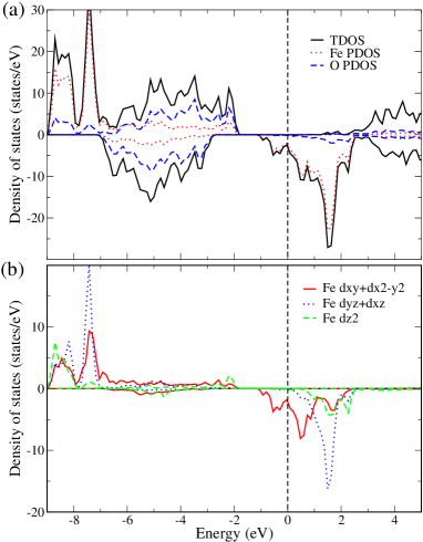
The GGA+U calculation for the non-CO state of LuFe2O4 with the room-temperature crystal structure and hence the hexagonal symmetry shows that all Fe ions are in the high spin state. The plots of density of states (DOS) calculated for the non-CO state (Fig. 2(a)) predict a metallic behavior for LuFe2O4, in disagreement with experiment. This is not surprising because the Fe ions are in the valence state of in the absence of CO. We found it impossible to produce an insulating band gap for any CO structure as long as the structure keeps the hexagonal symmetry. For a transition metal ion in a trigonal bipyramidal crystal field, the five states are split in three groups, i.e., {, }, {, } and {}. The partial DOS plots shown in Fig. 2(b) indicates that the down-spin bands leading to a metallic character arise from the and orbitals, i.e., the {, } states have a lower energy than do the {, } states for the FeO5 trigonal bipyramids in LuFe2O4.
To search for possible low-energy CO patterns, we resort to the classical MC simulation method by considering only the intersite Coulomb repulsion. This simplified approach is reasonable for the purpose of finding stable CO patterns. As the energy reference of this calculation, each Fe2.5+ site of the non-CO state is assumed to carry zero charge, so that, after a CO takes place, Fe3+ and Fe2+ sites will carry () and charges, respectively ( denotes the degree of the charge transfer). For simplicity, we assume that the charge on oxygen is independent of . We perform MC simulations using a supercell with periodic boundary conditions and evaluate the long-range Coulomb interaction using the Ewald sum method. There occur two different low-energy CO patterns. The most stable one is a chain-like CO structure (hereafter the CO-III structure) with energy eV per formula unit (FU), in which chains of Fe2+ ions alternate with those of Fe3+ ions in each triangular sheet (Fig. 1(d)). Given the trigonal symmetry of each W-layer, there are three different, but equivalent, ways of choosing the chain direction in each W-layer. When the three different chain orientations occur randomly, the overall superlattice diffraction pattern will exhibit a structure. The CO-I structure proposed by Yamada et al. is found to have a slightly higher energy, i.e., eV/FU. (The stability of this CO cannot be deduced by analogy with the spin configuration of Ising spins that occurs in a TLA when the nearest-neighbor (NN) spin exchange is antiferromagnetic and the next-nearest-neighbor (NNN) spin exchange is FM. This spin configuration becomes the ground state only when the NNN interactions are stabilizing. In the CO-I structure, the NNN interactions are destabilizing due to Coulomb repulsion.) Our MC simulations show that the CO-II structure proposed by Subramanian et al. is found to be highly unstable, namely, its energy is even higher than the non-CO structure by eV/FU. The instability of the CO-II structure is due to the large positive electrostatic energy between the ions of the same charge in each triangular sheet. We also consider MC simulations using another model that takes into consideration only the NN electrostatic interactions within each triangular sheet and between adjacent triangular sheets of every W-layer. Qualitatively, this model leads the same results as described above.
To more accurately probe the stabilities of the CO-I, CO-II and CO-III structures with respect to the non-CO structure, we carry out GGA+U calculations for LuFe2O4 on the basis of its crystal structure determined at RT. Our GGA+U calculations for the CO-II structure, with an initial guess of the charge density expected for it, always converged to the non-CO structure. Therefore, it is concluded that the CO-II structure is not stable, as found from our MC simulation. Since there are three W-layers per unit cell and since each W-layer has a nonzero dipole moment in the CO-I structure, there are two different arrangements of the W-layers in the CO-I structure, i.e., the FE arrangement (Fig. 1(e)) and the ferrielectric (FIE) arrangement (Fig. 1(f)). For the FE CO-I and the CO-III structures, our GGA+U calculations were carried out in two steps. In the first step, the FE CO-I or the CO-III structure was introduced in LuFe2O4 without allowing the crystal structure to relax. Such a CO induced solely by electrostatic interactions was first proposed by Attfield et al. Attfield and later computationally realized by Leonov et al. Leonov in their studies of the CO phenomenon in Fe2OBO3. In the second step, the crystal structure with the FE CO-I or the CO-III structure was completely optimized. Thus, the energy gain of the FE CO-I or the CO-III structure relative to the non-CO structure is written as , where and are the energy gains obtained in the first and second steps, respectively. arises from electrostatic interactions, and from the geometry relaxation.
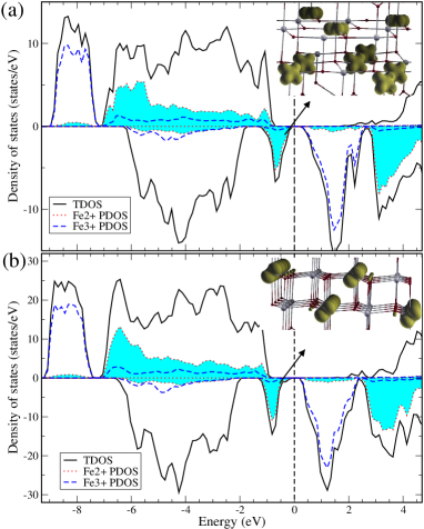
Our GGA+U calculations of the first step show that the FE CO-I and the CO-III structures are stable in the absence of geometry relaxation largeU (with 239 and 219 meV/FU, respectively), and are an insulator (with band gap of 0.18 and 0.15 eV, respectively). The forces acting on the atoms calculated for both CO structures with no geometry relaxation are large hence indicating instability of the “frozen” structure. Our GGA+U calculations of the second step show that the values of the FE CO-I and the CO-III structures are 163 and 165 meV/FU, respectively. Thus, after structural relaxation, the FE CO-I structure remains only slightly more stable than the CO-III structure (by 19 meV/FU). Another important finding of our calculations is that the energy gain resulting solely from electrostatic interactions is greater than that from geometry relaxation (i.e., ), in contrast to the case of Fe2OBO3, for which our calculations showed that (i.e., 77 vs. 272 meV) To_be_published . Bond-valence-sum calculations BVS for the optimized structures of the FE CO-I and the CO-III structures show that the valence states of the “Fe2+” and “Fe3+” sites are close to the nominal +2 and +3, respectively. Both CO structures have a larger band gap after geometry optimization (i.e., 0.70 and 0.54 eV for the FE CO-I and the CO-III structures, respectively). The DOS plots calculated for the FE CO-I and the CO-III structures with the relaxed structures are presented in Fig. 3. All the occupied up-spin 3d bands of the Fe2+ ions lead to a spherical charge distribution, and so do those of the Fe3+ ions. It is the occupied down-spin 3d bands of the Fe2+ ions that provide an anisotropic charge distribution arising from the Fe 3d orbitals and hence information about the orbital order (OO). This is shown in the insets of Fig. 3, which reveal that the two triangular sheets of a W-layer have an identical OO in the CO-III structure, but different OO’s in the FE CO-I structure. In the FE CO-I structure, the orbitals of the {, } type are involved in the OO of the triangular sheet of containing fewer Fe2+ ions than Fe3+ ions, but those of the {, } and {, } types in the other triangular sheet. In the CO-III structure, the orbitals of the {, } and {, } types are involved in the OO of both triangular sheets of a W-layer. The OO’s found for the unrelaxed structure are quite similar to those found for the optimized structures described above.
Experimentally, a large spontaneous electric polarization (EP) was found in LuFe2O4 Ikeda2005 . Of the two stable CO structures, CO-I and CO-III, only the CO-I structure has a nonzero EP. For the calculations of the spontaneous EP of the FE CO-I structure, we use the Berry phase method Berry . The calculated EP should be compared with the experimental one measured at a low temperature where there is no CF. The spontaneous EP along the c-axis is calculated to be 52.7 , which is much greater than the experimental value of about 25 measured at 77 K Ikeda2005 . To resolve this discrepancy, we consider the FIE CO-I structure (Fig. 1(f)). Our GGA+U calculations with complete geometry optimization show that the FIE CO-I structure is more stable than the FE CO-I structure by 12 meV/FU. The spontaneous EP along the c-axis calculated for the FIE CO-I structure is 26.3 , in excellent agreement with experiment. Thus, from the viewpoint of the total energy and the spontaneous EP, it is concluded that LuFe2O4 has the FIE CO-I structure. Note that the spontaneous EP for the FIE CO-I structure is smaller than that of FE CO-I structure by a factor of approximately two, instead of three expected from Fig. 1(e),(f). This is due to the fact the two crystal structures, which are each separately optimized, are slightly different.
Now we turn attention to the probable origin of the giant magnetocapacitance effect of LuFe2O4 at RT. According to our calculations, the two different CO structures, CO-I and CO-III, are very close in energy. Given the room-temperature structure of hexagonal symmetry, the CO-III state is higher in energy than the FE CO-I state only by 20 meV/FU. Thus, at RT, there should occur CFs associated with the interconversion between the two different CO states, which should form different domains separated by domain boundaries. Then, due to the large polarizability caused by the CFs, the dielectric constant of LuFe2O4 should be very large. Under an external magnetic field the Zeeman effect should preferentially stabilize one of the two CO states because the two states are most likely to have different total spin moments. Consequently, an external magnetic field will reduce the extent of CF and hence decrease the electron polarizability. The a.c. dielectric dispersion observed for LuFe2O4 can be understood in terms of the dielectric response and the motion of the FE domain boundaries between the CO-I and CO-III states Ikeda2005 . At present we cannot answer the question of which CO state will be preferentially stabilized by an external magnetic field, because only the FM spin arrangement was considered in the present work. Further studies are necessary to address this question.
We note that the spontaneous EP of LuFe2O4 is much greater than that of the recently discovered multiferroic materials (such as TbMnO3 Kimura2003 ), so LuFe2O4 represents a promising candidate for novel magnetoelectric devices.
We thank Dr. D. G. Mandrus, Dr. M. Angst and Prof. M. A. Subramanian for useful discussion. This work was supported by the Office of Basic Energy Sciences, Division of Materials Sciences, U. S. Department of Energy, under Grant No. DE-FG02-86ER45259.
References
- (1) O. Auciello et al., Phys. Today 51(7), 22 (1998); M. Dawber et al., Rev. Mod. Phys. 77, 1083 (2005).
- (2) R. E. Cohen, Nature (London) 358, 136 (1992).
- (3) N. Ikeda et al., Nature (London) 436, 1136 (2005).
- (4) M. A. Subramanian et al., Adv. Mater. 18, 1737 (2006).
- (5) M. Isobe et al., Acta Cryst. C46, 1917 (1990).
- (6) M Tanaka et al., J. Phys. Soc. Jpn. 53, 760 (1984).
- (7) Y. Yamada et al., Phys. Rev. B 62, 12167 (2000); N. Ikeda, et al., J. Phys. Soc. Jpn. 69, 1526 (2000); J. Iida et al., Physica B 155, 307 (1989).
- (8) K. Yoshii et al., Physica B 378, 585 (2006); N. Ikeda, et al., Ferroelectrics 314, 41 (2005), and references therein.
- (9) J. P. Wright et al., Phys. Rev. Lett. 87, 266401 (2001).
- (10) Y. Yamada et al., J. Phys. Soc. Jpn. 66, 3733 (1997).
- (11) P. E. Blöchl, Phys. Rev. B 50, 17953 (1994); G. Kresse and D. Joubert, ibid 59, 1758 (1999).
- (12) G. Kresse and J. Furthmüller, Comput. Mater. Sci. 6, 15 (1996); Phys. Rev. B 54, 11169 (1996).
- (13) J. P. Perdew et al., Phys. Rev. Lett. 77, 3865 (1996).
- (14) S. L. Dudarev et al., Phys. Rev. B 57, 1505 (1998).
- (15) J. P. Attfield et al., Nature (London) 396, 655 (1998).
- (16) I. Leonov et al., Phys. Rev. B 72, 014407 (2005); J. García and G. Subías, ibid 74, 176401 (2006); I. Leonov et al., ibid 74, 176402 (2006).
- (17) H. J. Xiang and M. -H. Whangbo, unpublished.
- (18) I. D. Brown and D. Altermatt, Acta Cryst. B 41, 244 (1985).
- (19) We first obtain the CO states using a large (e.g., = 7.61 eV) and then recalculate the CO states at a smaller (i.e., = 4.61 eV) using the converged densities with the larger . A large was employed only to generate an initial electron density with a desired CO state.
- (20) R. D. King-Smith and D. Vanderbilt, Phys. Rev. B 47, 1651 (1993); R.Resta, Rev. Mod. Phys. 66, 899 (1994).
- (21) T. Kimura et al., Nature (London) 426, 55 (2003).