Enhanced Spin Dependent Shot Noise in Magnetic Tunnel Barriers
Abstract
We report the observation of enhanced spin dependent shot noise in magnetic tunnel barriers, suggesting transport through localized states within the barrier. This is supported by the existence of negative magnetoresistance and structure in the differential conductance curves. A simple model of tunneling through two interacting localized states with spin dependent tunneling rates is used to explain our observations.
pacs:
72.25.Mk, 72.70.+m, 73.40.-c, 73.40.Gk, 73.40.Rw, 73.50.Td, 73.63.Rt, 85.75.MmI Introduction
Measurement of fluctuations or noise for gaining deeper understanding of the microscopic details of physical systems is not new. Shot noise measurements have been successfully used to measure the transport of fractional charge in two dimensional electron gas (2DEG) Hall regime systems saminadayar:1997 ; de-picciotto:1997 , to study 2e charge transport in superconductor-metal interfaces jehl:1999 ; jehl:2000 ; kozhevnikov:2000 , to detect localized states in point contact experiments in 2DEG’s chen:2006PRB ; safonov:136801 , and to probe transport details of many other systems dieleman:1997 ; reznikov:1995 ; kumar:1996 ; vanderbrom:1999 ; li:1990 ; steinbach:1996 ; liu:1998 . However, shot noise in magnetic systems has received much less attention. It is only recently that some predictions of the dependence of the shot noise on parameters such as the degree of spin polarization have been made tserkovnyak:2001 ; brataas:2000 ; lamacraft:2004 ; zareyan:2005 ; belzig:2004 ; mishchenko:2003 ; sauret:2004 ; braun:075328 ; bulka:2000 ; bulka:1999 ; belzig:2005 ; elste:2006 ; cottet:2004 . Corresponding shot noise experiments in magnetic systems are few, and have been done in frequency regimes where 1/f noise dominates nowak:1999 . In this paper we report the observation of enhanced spin dependent shot noise in magnetic tunnel junctions privcomm . Enhancement of the shot noise above the Poissonian limit in magnetic systems can occur via “spin blockade” due to the presence of a localized state, where a minority spin electron (with lower tunneling rate) can block the transport of majority spin electrons (with higher tunneling rate) braun:075328 ; bulka:2000 ; bulka:1999 ; belzig:2005 ; elste:2006 ; cottet:2004 . In nonmagnetic tunnel barriers it is also possible to observe super-Poissonian noise which has its origin in a similar type of blocking behavior whenever two localized states within the barrier are available for transport. An electron which tunnels into the state with the lower tunneling rates can block transport through the other localized state with higher tunneling rates, due to Coulomb interaction (“charge blockade”) safonov:136801 . Since in magnetic tunnel barriers both spin and charge blockade might occur, we compare our measurements with the results from calculations using both models. Our results are consistent with the model of two interacting localized states with spin dependent tunneling rates, implying that the observed super-Poissonian shot noise is due to both charge and spin blockade.
The paper is organized as follows. Section two discusses enhanced shot noise in nonmagnetic tunnel barriers due to two interacting localized states safonov:136801 and explains a classical model that can be used to calculate the Fano factor for arbitrary tunnel barriers buttcomm . Section three describes an additional mechanism for enhanced shot noise, particular only to magnetic tunnel junctions, and extends the model described in section two to include spin dependent tunneling rates. Section four describes the sample fabrication and experimental setup, while the results of the measurements and analysis are presented in section five. Finally, section six shows our conclusions.
II Shot Noise Enhancement in Nonmagnetic Tunnel Junctions
Electron transport across a tunnel junction can be characterized by a set of transmission coefficients , associated with the conducting channels across the junction. Within the Landauer-Büttiker formalism the total noise in a tunnel junction (both thermal plus non-equilibrium excess noise) is given by
| (1) | |||||
where , , and are the frequency, temperature, and voltage bias blanter:2000 . In the limit of , Eq. (1) reduces to
| (2) |
hence the Fano factor of such a junction is given by
| (3) |
cannot exceed one, that is, a regular tunnel junction exhibits only suppressed shot noise. This is equivalent to the statement that the transport statistics of a system with multiple uncorrelated sequential and/or parallel transport channels, each of which can be described by a Poissonian probability distribution, is exclusively sub-Poissonian. This was verified to a very good precision in atomic size metallic tunnel junctions vanderbrom:1999 . It thus came as a surprise when experimental observation of enhanced shot noise in a tunnel junction (which requires super-Poissonian statistics) was first reported safonov:136801 . The enhancement was explained using a model of interacting localized states inside the tunnel junction. Depending on the occupation state of one localized site, tunneling through the other site could be significantly modified due to the strong Coulomb interaction between the two sites. Such a modulated tunneling process could lead to largely enhanced shot noise, specially in small area tunnel barriers where the interaction between localized states is strongest. Our measurements in tunnel junctions formed by an electrostatic potential in 2DEG systems have also shown shot noise enhancement due to localized states chen:2006PRB ; chen:2006 . Shot noise in these junctions is very sensitive to microscopic details such as the distribution of localized states in real space, as well as their energy landscape. Figure 1 shows the shot noise as a function of current for one of our 2DEG point contacts for a fixed gate voltage. The shot noise can be either enhanced or suppressed by changing the current bias through the point contact, and is in general asymmetric with respect to the bias, reflecting the asymmetry in the position of the localized state. In our measurements, Fano factors between 0.3 and 14 have been observed on 25 barriers.

The probability distribution of tunneling events through a tunnel barrier with an arbitrary number of either sequential or parallel, and either interacting or independent transport channels can be constructed within a simple classical model using single channel tunneling events, each of which is characterized by a Poissonian probability distribution with tunneling rate . The resulting total probability distribution for an electron to tunnel completely across the barrier at exactly a time t after the previous tunneling event, can be either sub-Poissonian, Poissonian, or super-Poissonian. For particles with charge tunneling between two reservoirs with a general probability distribution , the average current is given by
| (4) |
and the Fano factor by davies:1992
| (5) |
where for a general function the expectation value is defined as .
For the particular case of tunneling through two interacting localized states we assume that the tunneling rates associated with each site are and ( = 1, 2). We further assume that due to Coulomb interaction once an electron hops into one state the other state will become unavailable for other electrons. The total probability distribution in this case is given by
| (6) | |||||
If the four tunneling rates are related by = = = , then the Fano factor calculated from Eqs. 5 and 6 is
| (7) |
Parameters and describe the asymmetry between left and right tunneling rates for each localized state, while describes the asymmetry in tunneling rates of the two localized states. Figure 2 shows as a function of at different values of and . The Fano factor has a minimum value of 0.5 when = and = . On the other hand, has no upper bound. In particular, can be much larger than 1 when is far away from 1, that is, when electrons dwell much longer in one site than in the other, effectively blocking transport through the faster channel.

Even tunneling rates which are less than one order of magnitude different give large values of . Since the tunneling rate depends exponentially on the distance between the localized state and the reservoir, even a small asymmetry in the position of the localized state within the barrier will give large differences in the left and right tunneling rates (this is specially true whenever the localization length is small). Therefore whenever two localized states are close enough so that one channel can block transport through the other, will be observed more often than . We performed numerical simulations to study the tunneling events in the time domain. A typical result is given in Fig. 2(c), where the “bunching” pattern in the tunneling events, which leads to enhanced shot noise, is clear. Unlike the “bunching” behavior observed for bosons where quantum statistics plays a role hanbury_brown:1956 ; morgan:1966 ; paul:1982 ; blanter:2000 , here it is purely due to Coulomb interaction. For magnetic tunnel barriers, however, another mechanism can also lead to “bunching” effects. This will be discussed in the next section.
III Magnetic Tunnel Junctions
In nonmagnetic tunnel barriers the tunneling rates for electrons with any spin orientation are considered to be equal. However in magnetic tunnel barriers this assumption is incorrect since the density of states in each of the magnetic electrodes is spin dependent. Therefore tunneling rates are larger for majority than for minority spins. This provides a different mechanism for generation of super-Poissonian statistics. Following the procedure described in the previous section, we can calculate the probability distribution for an electron to tunnel exactly at a time t after the previous tunneling event through a tunnel barrier with one localized state and spin dependent tunneling rates. It has the same form as Eq. 6, replacing the indices 1 and 2 by and . This is not surprising since in both situations (i) electrons tunnel into a localized state at two different rates (, in the case of 2 localized states, or , for spin dependent tunneling and a single localized state) and (ii) only one localized state can be occupied at any time. We have assumed that an external bias is applied in such a way that tunneling occurs from the left to the right reservoir. Assuming that and for , with the spin polarization (assumed to be the same for both magnetic electrodes) and the average tunneling rate for an electron with a definite spin state bulka:2000 , the Fano factor is given by
| (8) |
for the parallel magnetization state (P), while for the antiparallel state (AP) it is
| (9) |
Eq. 8 agrees with the calculations of Braun et. al braun:075328 who only give a closed form for the P state. For Eqs. 8 and 9 are equal and reduce to the case of nonmagnetic tunnel barriers, with tunneling rate from the left and tunneling rate to the right . This result shows that, in contrast to what is typically calculated for tunneling between nonmagnetic reservoirs through a barrier with a localized state, the minimum Fano factor occurs for an asymmetric position of the localized state, when . Tunneling into a localized state is proportional to the total density of states in the incoming reservoir but tunneling out of a localized state is proportional only to the density of states with spin , with the spin of the electron in the localized state spinflip . Therefore, for a symmetric localized state the left and right tunneling rates are different and give . Plots of the Fano factor as a function of the spin polarization are shown in Fig. 3 for (a) the P and (b) the AP states for different asymmetries between left and right tunneling rates. For large spin polarization the Fano factor in the P state can be much larger than 1, while in the AP state it has a maximum of 1.25 for and. This behavior has been termed “spin blockade” braun:075328 ; bulka:2000 ; bulka:1999 ; belzig:2005 ; elste:2006 ; cottet:2004 . It is important to note that both P states ( and ) have the same Fano factor and both AP states ( and ) have the same Fano factor . Only large spin polarizations produce significant shot noise enhancement.

It is then natural to consider the case of two interacting localized states, as discussed in the previous section, but now for magnetic tunnel barriers. This can be done in the same spirit as before, including spin dependent tunneling rates from the left reservoir to each of the localized states, and from the localized states to the right reservoir. Assuming equal spin polarization for both reservoirs, the set of 8 rates that describe the tunneling process can be reduced to 5 parameters, , , , , and p, which have been already defined in sections 2 and 3; however, the Fano factor is independent of . In this scenario the Fano factor of the AP state can be much larger than 1.25 (the maximum obtainable value for a single localized state). Furthermore both possibilities and can occur, as illustrated in Figures 3(c,d).
IV Experiment
Samples are fabricated on Si wafers with 500 nm of thermally grown oxide with a standard electron-beam lithography, thermal evaporation, and liftoff technique. A bilayer of PMGI and PMMA is used to create large controllable undercuts in the resist profile, which allows the use of double angle evaporation techniques, and therefore higher quality tunnel barriers that can be completely deposited without breaking vacuum, which in our system is typically in the 10-7 Torr range. First, 15 nm of Co are thermally evaporated at a low rate (typically 0.02 nm/s), after which a thin (2-4 nm) layer of Al is thermally evaporated at 0.01 nm/s. Then, the Al is oxidized at 800 to 2000 Torr-s, and the top 40 nm Co layer is deposited at a higher rate. The two Co electrodes have different geometry: the bottom electrode is typically 350 nm by 1.4 m while the top one is 120 nm by 1.4 m. Devices with different overlap areas between the two Co electrodes (typically between 0.005 nm2 and 0.06 nm2) are fabricated in order to achieve resistances in the proper range. The resistance of the devices is measured at room temperature, and samples with resistances lower than 30k and higher than 300k are discarded. Within a batch, most of the samples with similar Co overlap areas have similar resistance values. Devices are cooled down to 8K, and the resistance is measured again to ascertain if they have insulator-type of behavior and the resistance has increased. If metallic behavior is observed (i.e. the resistance decreases as the temperature is lowered) the sample is discarded since this shows that pinhole conduction is taking place mukhopadhyay:026601 (Rowell’s criteria rowell:1969 ).
Measurements are performed in a variable temperature cryostat equipped with an axial 9 T magnet (Quantum Design) and a custom built probe. For shot noise measurements the device is dc current biased while the noise voltage across the tunnel barrier is measured using a cryogenic preamplifier mounted less than 5 cm away from the sample. A complementary room temperature stage is used for further amplification after which a spectrum analyzer (HP89410A) samples the voltage noise in a flat frequency band in the 100kHz range where the effects of 1/f noise can be neglected. In situ calibration of the measured voltage is done with a photodiode (Lasermate, PDT-A85A30) wired in parallel to the tunnel barrier (see Fig. 4). A photocurrent with full shot noise is generated in the photodiode by

means of an LED, while the voltage drop across the tunnel barrier is nulled by applying an external current. This ensures that all of the current dependent noise comes from the photodiode. A single calibrated measurements consists of measuring the photodiode noise voltage power at a given current , the tunnel barrier noise at the same current, and the background noise at zero current. Each of the noise measurements must average more than 1000 noise spectra to give a good signal to noise ratio. From these averaged noise voltage powers it is possible to extract the Fano factor of the tunnel barrier at a current . In the limit , where thermal and excess noise can be well separated, the Fano factor is given by
| (10) |
Each of these calibrated measurements is performed 10-20 times and the results are again averaged. This increases the signal to noise ratio while minimizing the effects of drifts due to, for example, temperature changes in the electronics which affect the gain of the setup. Using this method it is possible to measure the shot noise from currents smaller than 1 nA, which produce voltage fluctuations of the order of 1 nV/Hz1/2. This is more than 20 times smaller than the thermal noise from the isolation resistors (Fig. 4), which is the main source of noise in the system. From now on we will discuss the results of the measurements of one of our devices, which shows the largest enhancement of the shot noise.
V Results and Discussion
The differential conductance of one of our devices is shown in Fig. 5(a), together with a symmetric linear fit. The most important features of the differential
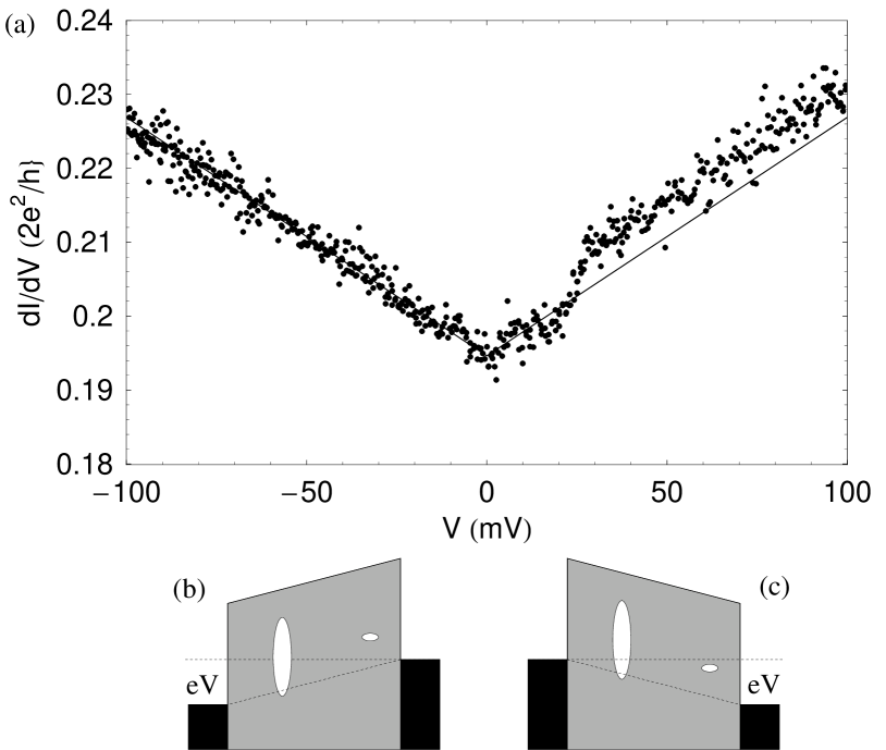
conductance are (i) its asymmetry, (ii) its linearity for negative bias, (iii) the transition to a higher conductance state above 30mV, and (iv) the fact that it is non-vanishing at zero bias. The transition to a higher conductance state which occurs between 20mV and 30mV suggests that an additional conductance channel, such as a localized state, with an energy resonance width of the order of 2-3mV, comparable to , has become available for transport. This localized state does not become available for transport in the negative bias regime. This can happen if the position of the localized state within the barrier is asymmetric as represented by the narrow resonance localized state in Figs. 5(b,c) (small ellipse towards the right of the barrier). However, even in the absence of transport through this localized state, the conductance is nonzero, which means that another channel must be available for transport at any bias. Furthermore, the conductance of this other channel increases linearly with the applied voltage. Models for direct tunneling do not agree with the linear increase in conductance since they predict a parabolic dependence on voltage. However, a reasonable scenario where this can happen is tunneling through an additional localized state above the Fermi energy which has a very wide resonance [large ellipsoid in Figs. 5(b,c)].
The resistance as a function of the in plane field parallel to the geometrical easy axis of the Co electrodes was then measured at different biases (Fig. 6 shows the magnetoresistance at a current of -0.627 A). Sharp resistance changes whenever the magnetization of either of the Co electrodes reverses are evident. The smoother transition is due to the slower reversal of the wider Co electrode, in which the effect of a magnetic easy axis not aligned with the geometrical easy axis is more evident. Two traces in both directions of magnetic field sweep illustrate that the transitions can occur at somewhat different fields, showing that the domain structure configuration after each demagnetization process can be different. However, there are ranges of magnetic field at which the device has a definite magnetization configuration and by applying a magnetic field any of the states , , , can be obtained.

An essential observation regarding Fig. 6 is that the value of the magnetoresistance,
| (11) |
is negative. Negative magnetoresistance was expected and has been observed in Co-SrTiO3 deteresa:1999 , Py-Ta2O5, and Py-Ta2O5/Al2O3 sharma:1999 systems, and reflects the importance of the compound effect of spacer and magnetic materials. However, negative MR has also been observed in systems which typically exhibit positive MR, and has been attributed to inversion due to pinhole transport mukhopadhyay:026601 , or to resonant tunneling through a localized state in the tunnel barrier tsymbal:186602 . From the insulator-like temperature dependence of the resistance we can rule out the possibility of pinhole conduction. This result, together with the differential conductance data presented earlier, provide evidence for conduction through localized states.
By applying a magnetic field, the sample is set to one of the four different identifiable magnetization states, , , , or , and the shot noise voltage power is measured as described before. Figure 7a shows the results of such measurements as a function of the current through the device, together with a dashed line representing the corresponding value of full shot noise (given by the noise from the photodetector). Figure 7(b) shows the measured Fano factor F as a function of the voltage across the tunnel barrier, calculated using the data from Fig. 7(a) and Eq. 10.

For positive bias the Fano factor is about 0.9, close to the full shot noise Fano factor of 1. The weak suppression of the shot noise can happen if electron tunneling through the barrier occurs in a sequential way through localized states within the barrier or via parallel channels. For example, tunneling through a localized state will give a Fano factor between 0.5 and 1 (Eq. 8 in the limit ), depending on the particular values of the tunneling rates, which themselves depend on the particular bias conditions, the shape of the tunnel barrier, and the position and energy of the localized state. These data further supports the claim for the existence of localized states within the barrier, which we used to explain the results of the differential conductance and magnetoresistance measurements. An important observation also regarding the positive bias region of Fig. 7(b) is that the Fano factor is very similar for the four different magnetization configurations. This can be explained by Eqs. 8 and 9 if there exists a large left-right asymmetry. For example, if and , the Fano factor is 0.875 for the P state and 0.877 for the AP state, which agree with the data within the experimental uncertainty. Even for higher values of the spin polarization it is possible to find ratios which give similar F for both P and AP states. For example gives 0.877 (0.838) for the P(AP) for p=0.4. Hence the simple model of tunneling through a single localized state described in section 3 is compatible with the positive bias Fano factor behavior.
However, the most interesting result of our measurements comes from the negative bias part of the shot noise data (Fig. 7), which show a very enhanced voltage dependent shot noise that varies strongly with the magnetization state of the contacts. As the voltage bias is decreased from zero the shot noise increases until it peaks at -13 mV. While the Fano factor for the state has a peak value close to 7, only increases to 3.6. In addition the state , which has a similar resistance to , shows a peak Fano factor of only 4.8. After -13 mV the shot noise decreases and by -58 mV it is already below the full shot noise value. At -80 mV the Fano factors for both P and AP states are close to their positive bias value and, within experimental uncertainty, they are equivalent. We have already explained the suppressed positive bias shot noise values as due to transport through a localized state. In order to understand the negative bias data we must explain first the existence of peaks in the shot noise, and second, their spin state dependence.
The simple model of section 3 does not contain any explicit voltage bias dependence, but it can be included by introducing voltage dependent tunneling rates, which require assumptions about the position and energy of the localized state, as well as information on the properties of the tunnel barrier (in the simplest approximation the width and height of the barrier). Calculations by Bulka bulka:2000 for magnetic tunnel barriers with a single localized state have shown that as the voltage bias across the barrier is increased, the shot noise (after subtracting the thermal noise) can increase quickly from zero up to a maximum super-Poissonian value and then decrease with larger bias to sub-Poissonian values. An asymmetry between positive and negative bias can be justified for an asymmetric position of the localized state [Fig. 5(b,c)] by observing Fig. 3(a), since for a fixed value of p (say p=0.8), gives F=0.88 but gives F=3.77. This qualitatively explains the existence of the peaks and why they appear only for the negative bias region.
However, the large peak values of the Fano factor and their dependence on the spin state can not be accounted for within the simple model of transport through a single localized state since it predicts, on the one hand, a maximum Fano factor of 1.25 for the AP state and, on the other hand, the same shot noise for both of the P states (FP=F↑↑=F↓↓) and both of the AP states (FAP=F↑↓=FFP). As pointed out by Tserkovnyak (private communication), the difference in Fano factor between the two P states and between the two AP states could be due to structural differences between these states. The magnetoresistance data (Fig. 6) already showed additional structure which might suggest that and , as well as and , are not equivalent states. The large AP state Fano factor can be explained assuming that two localized states contribute to transport, as illustrated in Fig. 3(c), where the Fano factor in the AP state can be not only larger than 1.25 (the maximum value in the case of transport through a single localized state) but even larger than the Fano factor for the P state. The dashed lines in Fig. 3(c) illustrate that values of the asymmetry parameters and the spin polarization (for example, p=0.47) can be

chosen in order to give Fano factors which agree (, ) with the measured peak values. Similar Fano factors can be obtained for both larger and smaller values of the spin polarization by choosing different combinations of the asymmetry parameters ,, and .
Detailed data from a different cooldown in which only and were measured in the negative bias region are shown in Fig. 8. Although the size of the peaks is different, the voltage at which they occur is unchanged. The different peak size can be due to differences in the magnetic states of the electrodes, as well as to differences in the properties of the localized states after thermal cycling.
VI Conclusions
We have made differential conductance, magnetoresistance, and shot noise measurements in small area magnetic tunnel barriers, which give evidence for transport through two competing localized states. The shot noise is enhanced above its Poissonian value at certain voltages and it is in these regions of super-Poissonian behavior that a strong dependence of the Fano factor on the magnetization state of the ferromagnetic electrodes is observed. Such behavior is explained by using a simple probabilistic model for tunneling through two strongly interacting localized states, taking into account the spin dependence of the tunneling rates. The enhancement of the Fano factor is due to a combination of “spin blockade” where minority spin electrons block the transport of majority ones, and “charge blockade” where an electron that tunnels into a localized state with small tunneling rate (slow channel) blocks transport through the other faster channel due to Coulomb interaction. The voltage dependence of the Fano factor (both the existence of a peak, and the positive/negative bias asymmetry) can be qualitatively understood as a change in the tunneling rates when the resonant energies of the localized states move with respect to the chemical potentials of each reservoir. However, a complete model which includes explicit voltage dependence of the conductance and the shot noise is missing.
We thank Y. Tserkovnyak for helpful discussions.
References
- (1) L. Saminadayar, D. C. Glattli, Y. Jin, B. Etienne, Phys. Rev. Lett. 79 (1997) 2526–2529.
- (2) R. De-Picciotto, M. Reznikov, M. Heiblum, V. Umansky, G. Bunin, D. Mahalu, Nature 389 (1997) 162–164.
- (3) X. Jehl, P. Payet-Burin, C. Baraduc, R. Calemczuk, M. Sanquer, Phys. Rev. Lett. 83 (1999) 1660–1663.
- (4) X. Jehl, M. Sanquer, R. Calemczuk, D. Mailly, Nature 405 (2000) 50–53.
- (5) A. A. Kozhevnikov, R. J. Schoelkopf, D. E. Prober, Phys. Rev. Lett. 84 (2000) 3398–3401.
- (6) Y. Chen, R. A. Webb, Phys. Rev. B 73 (2006) 035424.
- (7) S. S. Safonov, A. K. Savchenko, D. A. Bagrets, O. N. Jouravlev, Y. V. Nazarov, E. H. Linfield, D. A. Ritchie, Phys. Rev. Lett. 91 (2003) 136801.
- (8) P. Dieleman, H. G. Bukkems, T. M. Klapwijk, M. Schicke, K. H. Gundlach, Phys. Rev. Lett. 79 (1997) 3486–3489.
- (9) M. Reznikov, M. Heiblum, H. Shtrikman, D. Mahalu, Phys. Rev. Lett. 75 (1995) 3340–3343.
- (10) A. Kumar, L. Saminadayar, D. C. Glattli, Y. Jin, B. Etienne, Phys. Rev. Lett. 76 (1996) 2778–2781.
- (11) H. E. van den Brom, J. M. van Ruitenbeek, Phys. Rev. Lett. 82 (1999) 1526–1529.
- (12) Y. P. Li, A. Zaslavsky, D. C. Tsui, M. Santos, M. Shayegan, Phys. Rev. B 41 (1990) 8388–8391.
- (13) A. H. Steinbach, J. M. Martinis, M. H. Devoret, Phys. Rev. Lett. 76 (1996) 3806–3809.
- (14) R. C. Liu, B. Odom, Y. Yamamoto, S. Tarucha, Nature 391 (1998) 263.
- (15) Y. Tserkovnyak, A. Brataas, Phys. Rev. B 64 (2001) 214402.
- (16) A. Brataas, Y. V. Nazarov, G. E. W. Bauer, Phys. Rev. Lett. 84 (2000) 2481–2484.
- (17) A. Lamacraft, Phys. Rev. B 69 (2004) 081301.
- (18) M. Zareyan, W. Belzig, Phys. Rev. B 71 (2005) 184403.
- (19) W. Belzig, M. Zareyan, Phys. Rev. B 69 (2004) 140407.
- (20) E. G. Mishchenko, Phys. Rev. B 68 (2003) 100409.
- (21) O. Sauret, D. Feinberg, Phys. Rev. Lett. 92 (2004) 106601.
- (22) M. Braun, J. Konig, J. Martinek, Phys. Rev. B 74 (2006) 075328.
- (23) B. R. Bułka, Phys. Rev. B 62 (2000) 1186–1192.
- (24) B. R. Bułka, J. Martinek, G. Michałek, J. Barnaś, Phys. Rev. B 60 (1999) 12246–12255.
- (25) W. Belzig, Phys. Rev. B 71 (2005) 161301.
- (26) F. Elste, C. Timm, Phys. Rev. B 73 (2006) 235305.
- (27) A. Cottet, W. Belzig, C. Bruder, Phys. Rev. Lett. 92 (2004) 206801.
- (28) E. R. Nowak, M. B. Weissman, S. S. P. Parkin, Appl. Phys. Lett. 74 (1999) 600–602.
- (29) While writing this paper, private correspondence with Dr. Tserkovnyak made us aware of the new results of Guerrero et. al, to be published in PRL, which show spin dependent noise in magnetic tunnel barriers. In their experiments, Guerrero et. al observe weakly bias dependent shot noise which is mostly supressed. On the other hand, our results show that strongly bias dependent enhanced shot noise can also be observed in magnetic tunnel junctions.
- (30) According to Blanter and Buttiker, classical calculations of the shot noise typically agree with the full quantum calculations when ensemble averaging is performed. Our simple classical calculations have been compared with those of Blanter et. al and Braun et. al and they have been found to agree.
- (31) Y. M. Blanter, M. Büttiker, Phys. Rep. 336 (2000) 1–2.
- (32) Y. Chen, R. A. Webb, Phys. Rev. Lett. 97 (2006) 066604.
- (33) J. H. Davies, P. Hyldgaard, S. Hershfield, J. W. Wilkins, Phys. Rev. B 46 (1992) 9620–9633.
- (34) R. Hanbury-Brown, R. Twiss, Nature 178 (1956) 1046.
- (35) B. L. Morgan, L. Mandel, Phys. Rev. Lett. 16 (1966) 1012–1015.
- (36) H. Paul, Rev. Mod. Phys. 54 (1982) 1061–1102.
- (37) This discussion assumes that there is no spin-flip scattering in the tunneling process.
- (38) S. Mukhopadhyay, I. Das, Phys. Rev. Lett. 96 (2006) 026601.
- (39) J. M. Rowell, Tunneling Phenomena in Solids, Plenum, New York, 1969.
- (40) J. M. De Teresa, A. Barthélémy, A. Fert, J. P. Contour, R. Lyonnet, F. Montaigne, P. Seneor, A. Vaurès, Phys. Rev. Lett. 82 (1999) 4288–4291.
- (41) M. Sharma, S. X. Wang, J. H. Nickel, Phys. Rev. Lett. 82 (1999) 616–619.
- (42) E. Y. Tsymbal, A. Sokolov, I. F. Sabirianov, B. Doudin, Phys. Rev. Lett. 90 (2003) 186602.