Spin-Current-Induced Charge Accumulation and Electric Current in Semiconductor Nanostructures with Rashba Spin-Orbit Coupling
Abstract
We demonstrate that the flow of a longitudinal spin current with different spin polarization will induce different patterns of charge accumulation in a two-terminal strip, or electric current distribution in a four-terminal Hall-bar structure, of two-dimensional electron gas with Rashba spin-orbit coupling (RSOC). For an in-plane polarized spin current, charges will accumulate either by the two lateral edges or around the center of the strip structure while, for an out-of-plain polarized spin current, charge densities will show opposite signs by the two lateral edges leading to a Hall voltage. Our calculation offers a new route to experimentally detect or differentiate pure spin currents with various spin polarization.
pacs:
85.75.-d, 72.20.My, 71.10.CaSemiconductor spintronics has achieved remarkable success in the past decade and is still progressing rapidly. And spin-orbit science and engineering, which allow for electrical manipulation of spin polarization and spin currents in nonmagnetic semiconductors, is one of the key steps to implement spintronic devices.Prinz98Science Utilizing spin-orbit coupling, various schemes were proposed to generate pure spin currents,Dyakonov71 while to detect pure spin currents remains a challenge from either experimental or theoretical aspect. The detection of spin currents often involves spin accumulation or electrical effects, despite quantum interferences by optical means also reported.Hubner03prl For example, spin accumulation induced by spin current near the boundaries has been detected in both n- and p-doped semiconductor systems experimentally,Kato04Science and Hall voltage resulted from the reciprocal extrinsic spin Hall effect was observed in diffusive metallic conductors.Valenzuela06 ; Saitoh06apl Recently it was reported that an optically injected spin current flowing through a Hall-bar semiconductor can generate either in-ward or out-ward electric currents while the Hall voltage remains zero.Cui06 This observation renders a manifestation of the tensor-like nature of the spin current, which means that both the spin polarization and the direction of motion are decisive factors in producing physically observable effects.
The electrical detection of spin currents has reduced complexities in practice and thus is potentially more applicable.Valenzuela06 ; Saitoh06apl ; Cui06 Whereas a fundamental problem of theoretically studying the electrical effects resulted from spin currents, is the difficulties to incorporate the concept of spin current into a theoretical formalism, for reasons like the ambiguous definition of spin currents under certain circumstances.Shi06prl In this Letter we investigate such effects in a mesoscopic system of spin-orbit-coupled two-dimensional gas (2DEG) with ideal leads which connect several special electron reservoirs. Generation of the spin current is simulated phenomenologically by introducing spin-dependent chemical potentials within each electron reservoir. These chemical potentials are tuned separately for each spin component to produce independent potential gradients, so that electrons with opposite spins are driven to move in opposite directions through the spin-conserved leads and the spin-orbit-coupled central region. It must be emphasized that the aim of this phenomenological simulation is to capture only the general and essential features of the spin current flow, without bothering about the details of the method in its generation and injection, and this is justified as long as we keep our focus on the electrical effects that are led by or intimately related to the circulation of the spin current.
We demonstrate spin-current-induced electrical effects by showing charge accumulation induced in a strip structure and the electric current distribution in a corresponding Hall-bar structure. The Landauer-Büttiker-Keldysh formalism is used in our calculations, which is a quantum-in-nature approach and has extensive application.Sheng05prl The total Hamiltonian of the central region is , where is the kinetic energy plus the hard-wall confining potential , is the effective electron mass, and , with the strength of Rashba spin-orbit coupling (RSOC), the wave vector, the vector composed of Pauli’s matrices, and the unit vector perpendicular to the plane of the 2DEG. After discretizing with the tight-binding approximation and transforming it into the spin bases which are the eigenstates (denoted by or where or ) of , where is the orientation of spin polarization under consideration, we have
| (1) |
where and are the creation and annihilation operators of electrons at sites with spin and means the pairs of nearest neighboring (n.n.) sites, and
where is the unit vector displacement between two n.n. sites in direction, is the overlap integral of two n.n. sites with the average spacing between two n.n. sites, , is the identity matrix, and is the unitary matrix which rotates to . To count in the effect of the semi-infinite ideal leads, self-energy terms are introduced, , with the specific term due to lead in the spin diagonal block is
| (2) |
where is the eigenfunction in the transverse dimension at site in lead which is adjacent to site in the central region, and is the wave vector along the semi-infinite lead. Here we assume that there is no spin-orbit coupling in the leads. This not only guarantees that the spin currents under our investigation is well-defined from experimental aspect, but also is justified because it turns out that the interface mismatch between the leads and the central part actually contributes little to the patterns we observed. The retarded Green’s function , and the lesser Green’s function is given by the Keldysh equation , with , where is the spin-dependent chemical potential for electrons of spin in the lead , and is the Fermi-Dirac distribution function. Expressed in terms of the lesser Green’s function, when a steady state is achieved, the non-equilibrium charge density at site is
| (3) |
and the electric bond current from site to site is
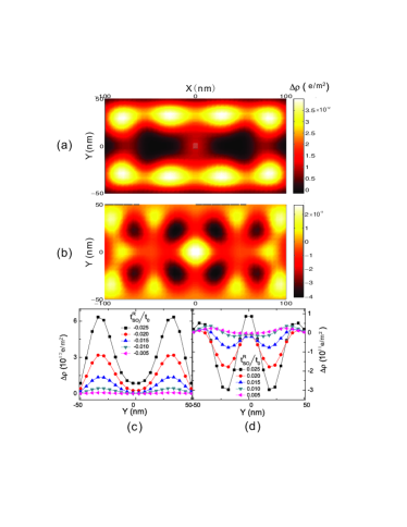
Our present study focuses on electrical effects resulted from spin current with spin polarization orientated in plane (referred to as henceforth) which is perpendicular to the direction of motion (referred to as henceforth) of electron spin. When a spin current with -spin-polarization is flowing through a strip, depending upon the sign of the RSOC , which stands for whether the velocity, the spin polarization and the gradient of potential for the RSOC satisfy the left-hand or right-hand chirality, the electric charges will accumulate either near the lateral edges or around the middle of stripe, as shown in Fig.1. In this figure, two equal-magnitude /-spin-polarized current are driven in the direction / by the spin-dependent chemical potentials through a lattice with the Fermi Energy , which is measured from the bottom of the conduction band and is small enough to ensure the parabolic energy-momentum dispersion in the tight-binding approximation, and eVm or in Fig.1(a), and eVm or in Fig.1(b), respectively. It is easy to identify that the charges of carriers accumulate by the two lateral edges in the former case and at the middle part in the latter one. This is further manifested by a comparison of Fig.1(c) and Fig.1(d), where the averaged charge densities with are plotted. For a negative , increased magnitude will lead to increased accumulation by the edges, while for a positive , the same trend happens at the middle. It should be noted that since we do not consider any dissipation mechanisms inside our samples, these accumulations should be interpreted as an effect purely due to quantum coherent transport.
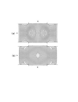
To show physical consequences of charge accumulation in a strip structure, we calculated electric current distributions in a Hall-bar structure where two additional leads are symmetrically attached to the two lateral sides of the original strip as illustrated in Fig.2. The current distribution for either sign of in this structure has remarkable consistence with the charge accumulation in the corresponding strip system in terms of that the additional leads act just as the pathways for the accumulated charges to flow through. Specifically, when , charges accumulated by the lateral edges will flow outward through the two transverse leads and at the same time the net charges will be drawn though the two longitudinal leads, while when , the charges tend to be drawn inward through two transverse leads and flow out through two longitudinal ones, which accounts for the accumulation of charges around the center of the strip-shaped sample. Quantitatively, the induced electric current in each transverse lead sums up to be typically two orders less than the magnitude of the total circulating spin current. These observations are also fully consistent with the electric current patterns in referenceLi06apl where the linear response approximation are adopted to produce the results.
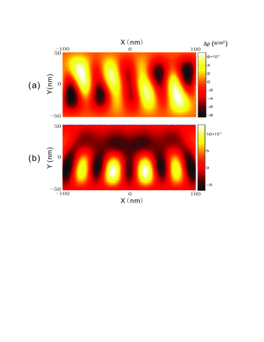
So far we have mainly discussed the charge density and the electric current distribution induced by a spin current with in-plane spin polarization (along ). Yet a tensor as a spin current is in essence, it is also worthwhile to investigate the spin current with different configurations of spin polarization and velocity. Without losing the generality, we concentrate on three cases of spin along , and , respectively. From the study of these special cases, the generic result for a spin current with arbitrary spin polarization can be derived, and also maximum symmetries can be observed therein. Since one of these cases with -spin-polarization has been presented already, we show the charge distributions induced in other two cases in Fig.3. Compared with the induced charge distribution shown in Fig.1(b), which is calculated with all the same parameters except for the spin polarization of the spin current, the induced charge distributions in Fig.3(a) and (b) show clear differences in terms of the spacial symmetries they possess, that is the symmetry in the case when spin polarized along , the symmetry when spin polarized along , and the symmetry when spin polarized along .Hamermesh This is because the underlying system is invariant under each operation of the space group combined with an appropriate unitary transformation in the spin space, while in order that the circulating spin current is also invariant under that combination of transformations, the valid space-group operations will be limited into a subgroup of ( itself in the -spin-polarization case, and or in the - or -spin-polarization case respectively), accordingly the charge distributions induced by different spin currents will exhibit different symmetry properties. Also it is easy to infer that the electric current distributions or any other electric effect induced by a corresponding spin current will display the same spacial symmetry as long as the structural symmetry of the system is preserved, which is actually a general yet rigorous limitation and has been justified in all our calculations that are shown or not shown here.
Moreover, the relevance of the spin polarization of spin current to the induced charge accumulation also lies in the differences between the average distributions along the transverse of the strip resulted from spin currents which are polarized in different directions. In particular, Fig.1(c) and (d) show that the charges of carriers tend to accumulate, depending on the sign of , either by both of the two lateral edges or around the center of the sample when the spin current is polarized along . When the spin current is polarized along , however, it can be observed from Fig.3(b) that the charge accumulation on average will have opposite signs near the two lateral edges, which is closely related to as well as consistent with the reciprocal version of the spin Hall effect,Shi06prl ; Hankiewicz05prb and was reported to be observed in platinum wires.Saitoh06apl In another case that the spin current with -spin-polarization is considered, the pattern of the charge accumulation (shown in Fig.3(a)) is more complex in the sense that there are reversed accumulating trends at the two sides of the transverse plane passing through the symmetric center, which is determined by the symmetry of this system mentioned above. While after average has been taken over the longitudinal dimension, it can be reasonably expected that the opposite accumulations of two halves will tend to cancel each other and produce a weakened net effect with symmetrical distribution about the transversal center. In contrast to that in the -spin-polarized case, in either case with the - or -spin-polarization, the averaged distribution along the traverse does not change under the reversal of the sign of . Besides, we notice that the electric effects induced by different spin currents are actually contributed by different ranks of power with respect to , which is also manifested when the sign of is reversed. Specifically, when the spin current is polarized along or , it is mainly the linear that is responsible for the induced electric effects, while in the -spin-polarized case, it is the second rank, i.e. , playing the role.
We conclude this letter by evaluating the accessibility of an experimental observation to the electrical patterns investigated here. From the data plotted in Fig.1(c), we estimate roughly the electrostatic potential difference to be of order mV between either of the peaks and the valley of the charge distribution as long as eVm. And in a realistic semiconductor quantum well with the Fermi energy typically being tens of meV, the electronic potential difference will increase to at least several meV or tens of Kelvins subject to increased RSOC strength. This implies that the temperature requirement for observing these patterns can be well satisfied within current experimental conditions. Regarding these features as well as the sample size, we propose the use of Kelvin probe force microscopyKPFM in observing the charge accumulation predicted here. On the other hand, we point out that the present work may also account for a recent experimental observation of the spin-current-induced electric currents,Cui06 which possess the key features exhibited in Fig.1 and Fig.2, that is, there is no Hall voltage while the electric currents circulate through -channels to -channels. And quantitatively the experiment is consistent with the calculated ratio of the induced charge current to the spin current captioned in Fig.1. In short, the spin current with in-plane spin polarization may produce measurable charge accumulations or electric currents with a novel behavior, and the underlying effects may open a promising way to the electrical detection of spin currents.
The author would like to thank Xiao-Dong Cui and Fu-Chun Zhang for helpful discussions. This work was supported by the Research Grant Council of Hong Kong under Grant No.: HKU 0742/06P.
References
- (1) G. A. Prinz, Science 282, 1660 (1998); S. A. Wolf, D. D. Awschalom, R. A. Buhrman, J. M. Daughton, S. von Molnar, M. L. Roukes, A. Y. Chtchelkanova, and D. M. Treger, Science 294, 1488 (2001).
- (2) M. I. D’yakonov and V. I. Perel, JETP Lett. 13, 467 (1971); J. E. Hirsch, Phys. Rev. Lett. 83, 1834 (1999); J. Sinova, D. Culcer, Q. Niu, N. A. Sinitsyn, T. Jungwirth, and A. H. MacDonald, Phys. Rev. Lett. 92, 126603 (2004); S. Murakami, N. Nagaosa, and S. C. Zhang, Science 301, 1348 (2003); S.-Q. Shen, M. Ma, X. C. Xie, and F. C. Zhang, Phys. Rev. Lett. 92, 256603 (2004); R. D. R. Bhat and J. E. Sipe, Phys. Rev. Lett. 85, 5432 (2000); B. Wang, J. Peng, D. Y. Xing, and J. Wang, Phys. Rev. Lett. 95, 086608 (2005); A. G. Mal’shukov, C. S. Tang, C. S. Chu, and K. A. Chao, Phys. Rev. B 68, 233307 (2003)
- (3) J. Hubner, W. W. Ruhle, M. Klude, D. Hommel, R. D. R. Bhat, J. E. Sipe, and H. M. van Driel, Phys. Rev. Lett. 90, 216601 (2003); M. J. Stevens, A. L. Smirl, R. D. R. Bhat, A. Najmaie, J. E. Sipe, and H. M. van Driel, Phys. Rev. Lett. 90, 136603 (2003); H. Zhao, E. J. Loren, H. M. van Driel, and A. L. Smirl, Phys. Rev. Lett. 96, 246601 (2006).
- (4) Y. K. Kato, R. C. Myers, A. C. Gossard and D. D. Awschalom, Science 306, 1910 (2004); J. Wunderlich et al., Phys. Rev. Lett. 94, 047204 (2005); V. Sih, R. C. Myers, Y. K. Kato, W. H. Lau, A. C. Gossard, and D. D. Awschalom, Nature Physics 1, 31 (2005).
- (5) S. O. Valenzuela and M Tinkham, Nature 442, 176 (2006).
- (6) E. Saitoh, M. Ueda, H. Miyajima, and G. Tatara, Appl. Phys. Lett. 88, 182509 (2006); T. Kimura, Y. Otani, T. Sato, S. Takahashi, and S. Maekawa, Phys. Rev. Lett. 98, 156601 (2007).
- (7) X. D. Cui, S. Q. Shen, J. Li, Y. Ji, W. Ge, and F. C. Zhang, Appl. Phys. Lett. 90, 242115 (2007).
- (8) J. R. Shi, P. Zhang, D. Xiao, and Q. Niu, Phys. Rev. Lett. 96, 076604 (2006).
- (9) L. Sheng, D. N. Sheng, and C. S. Ting, Phys. Rev. Lett. 94, 016602 (2005); B. K. Nikolic, S. Souma, L. P. Zarbo, and J. Sinova, Phys. Rev. Lett. 95, 046601 (2005); E. M. Hankiewicz, L. W. Molenkamp, T. Jungwirth, and J. Sinova, Phys. Rev. B 70, 241301(R) (2004); J. Li, L. Hu, and S. Q. Shen, Phys. Rev. B 71, 241305(R) (2005).
- (10) J. Li, X. Dai, S. Q. Shen, and F. C. Zhang, Appl. Phys. Lett. 88, 162105 (2006).
- (11) M. Hamermesh, Group theory and its application to physical problems, (Reading, Mass. 1962).
- (12) E. M. Hankiewicz, J. Li, T. Jungwirth, Q. Niu, S. Q. Shen, and J. Sinova, Phys. Rev. B 72, 155305 (2005).
- (13) M. Nonnenmacher, M. P. Oboyle, and H. K. Wickramasinghe, Appl. Phys. Lett. 58, 2921 (1991); X. D. Cui, M. Freitag, R. Martel, L. Brus, and P. Avouris, Nanoletter 3, 783 (2003).