Shear flow pumping in open microfluidic systems
Abstract
We propose to drive open microfluidic systems by shear in a covering fluid layer, e.g., oil covering water-filled chemical channels. The advantages as compared to other means of pumping are simpler forcing and prevention of evaporation of volatile components. We calculate the expected throughput for straight channels and show that devices can be built with off-the-shelf technology. Molecular dynamics simulations suggest that this concept is scalable down to the nanoscale.
Progressive miniaturization and integration of chemical and physical processes into microfluidic systems, so-called “chemical chips”, is expected to permit cheap mass production and to facilitate the handling of much smaller quantities than standard laboratory equipment Giordano and Cheng (2001); Mitchell (2001); Stone and Kim (2001). Most currently built microfluidic systems contain the liquids in closed pipes and use body forces (e.g., gravity or centrifugal forces) Gustafsson et al. (2003), electroosmosis, capillary wicking, or simply applied pressure to generate flow. Driving these systems is relatively straightforward, but there are major drawbacks. Small pipes get easily clogged (in particular while processing biological fluids which contain large molecules such as proteins or DNA), driving gets increasingly difficult with reduced cross section, and fabrication more challenging.
Open microfluidic systems are a second line of development which can overcome these problems. As demonstrated experimentally Darhuber et al. (2001); Gau et al. (1999) and theoretically Dietrich et al. (2005); Koplik et al. (2006), fluids can be guided on flat solid surfaces by wettability patterns, e.g., hydrophilic stripes on an otherwise hydrophobic substrate. Several methods to generate flow in such ”chemical channels“ have been discussed: capillary forces (i.e., wicking into channels or motion due to wettability gradients) Darhuber et al. (2001), electrowetting Srinivasan et al. (2004); Zeng and Korsmeyer (2004), thermally generated Marangoni forces (e.g., in arrays of local heaters) Farahi et al. (2004); Kotz et al. (2004), body forces, surface acoustic waves Guttenberg et al. (2005), or combinations of these. While capillary forces can only induce flow over relatively short distances, electrode and heater arrays require complex sample structures. Surface acoustic waves can only drive drops which are large compared with the wavelength (in general on the micron scale), and high rotation velocities are required to obtain sufficiently strong centrifugal forces.
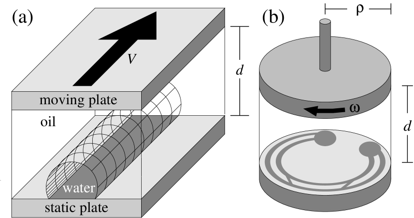
As illustrated in Fig. 1 we propose to use shear, generated in a covering fluid layer (e.g., oil on water), to induce flow over long length scales, e.g., across the whole device. A top plate moving with respect to the bottom patterned substrate generates shear in the oil which fills the gap between the two plates and, in turn, the oil will induce flow in a chemical channel covered with, e.g., water. This principle can be realized in a device with two circular plates rotating relative to each other and the chemical patterning can be implemented with standard printing techniques Abbott et al. (1999); Zhao et al. (2002). Design and scalability of shear driven systems is similar to body force driven devices and the same type of surface tension driven pearling instabilities occur in straight channels Koplik et al. (2006). In both cases pearl formation increases throughput through the channels. This driving principle can be extended easily to water confined in open topographic channels Seemann et al. (2005), although it will be more efficient in open chemical channel systems as there the water has less contact with the substrate (due to the lack of sidewalls).
In the following we calculate the throughput for a shear driven straight chemical channel in two simple cases. Using molecular dynamics simulations of a system of two immiscible model fluids we demonstrate that shear driving can be downscaled to the nanometer scale. We conclude by discussing how the principle of shear driving can be realized in a device of the size of a miniature computer hard disk (microdrive).
In order to estimate the possible throughput we consider the simple case of a straight and homogeneously filled chemical channel aligned parallel to the shear flow in the covering oil layer. We assume that the three phase contact line is pinned at the channel edges. In microfluidic devices the Reynolds number is typically small so that one has Stokes flow. For two situations one can solve the corresponding hydrodynamic equations analytically: (i) the water-oil interface meets the substrate surface at a contact angle of , (ii) the viscosities of the oil and water are equal.
Figure 2 shows a cross section in a plane orthogonal to the chemical channel of width . Far from the channel we assume a constant shear rate . We seek solutions of the Stokes equation with the flow parallel to the channel (i.e., normal to the plane depicted in Fig. 2). In this case, the pressure in the system is constant and the velocity component parallel to the channel satisfies a Laplace equation
| (1) |
in both the water and the oil, with viscosity and , respectively. By symmetry, the other velocity components are zero. For Couette flow in a homogeneous medium between two parallel moving plates (Fig. 1(a)) the solution of Eq. (1) is , with a spatially and temporally constant shear rate . In order to be able to use polar coordinates with the origin at the center of the chemical channel we take this solution as a boundary condition on an outer circle with radius , i.e., (Fig. 2). We apply a no-slip boundary condition at the liquid-substrate interface for both fluids, i.e., . At the interface between the two liquids the difference between the normal components of the stress is given by the Laplace pressure. For the geometry considered here this reduces to the condition that the interface has a constant curvature, i.e., it is a semicircle of radius . The velocity field, , as well as the tangential stress components, , are continuous. For , the corresponding solution of Eq. (1) is
| (2) |
For the flux (or throughput) , with the channel cross section , is given by
| (3) |
see Fig. 3. It increases with . The throughput can be characterized also by the apex velocity , i.e., the fluid velocity at and :
| (4) |
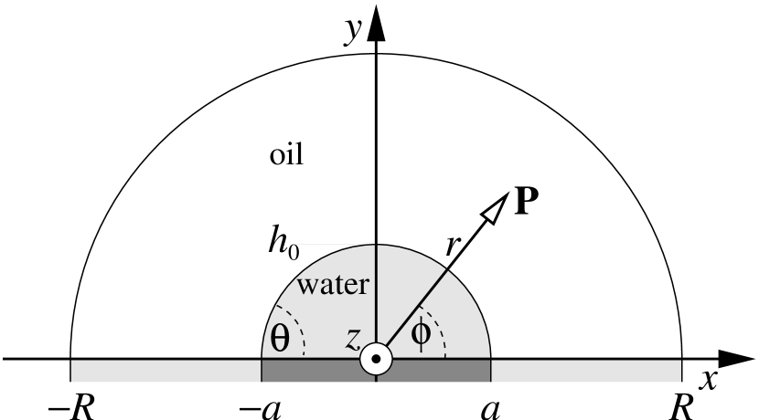

For the flow field is not influenced by the presence of the liquid-liquid interface as long as the former is translationally invariant along the channel. Accordingly, the velocity field is
| (5) |
Eq. (5) implies as water flux through a channel with a cross section forming a circular segment with filling height (see Fig. 2)
| (6) |
so that (see Fig. 3).
In order to suggest that shear driven microfluidics can be miniaturized to the nano-scale, we have performed molecular dynamics simulations as a well suited approach in this regime. To a large extent we have used standard techniques Allen and Tildesley (1987); Frenkel and Smit (2002); Koplik and Banavar (1995) with the implementation of the dynamics on wetting stripes following Ref. Koplik et al. (2006). The model system consists of two immiscible monatomic fluids and two types of wall atoms, with Lennard-Jones interactions truncated at , where is the interatomic separation, measures the size of the repulsive core, is the strength of the potential, and is a dimensionless parameter that controls the attraction between atoms of the four atomic species and . The temperature is set to by a Nosé-Hoover thermostat. The liquids are confined between solid walls at a distance , each composed of a layer of fcc unit cells (with lattice constant ) whose atoms are tethered to lattice sites with a stiff linear spring. Periodic boundary conditions are applied in the two lateral directions. Couette flow is achieved by translating the tether sites of the upper wall at a constant velocity. Most of the interaction strengths have the standard value , but if and refer to different liquids, or the inner liquid (the ”water”) and the non-wetting part of the wall, or the outer liquid (the ”oil”) and the wetting part of the wall, or to wall atoms. With these choices, the two liquids are completely immiscible. Because the interactions among atoms of each of the two species are identical, they have equal density and viscosity. A number of different system sizes have been simulated, all giving similar results; the largest contained about 1.25 million atoms in total, with wetting stripe dimensions .
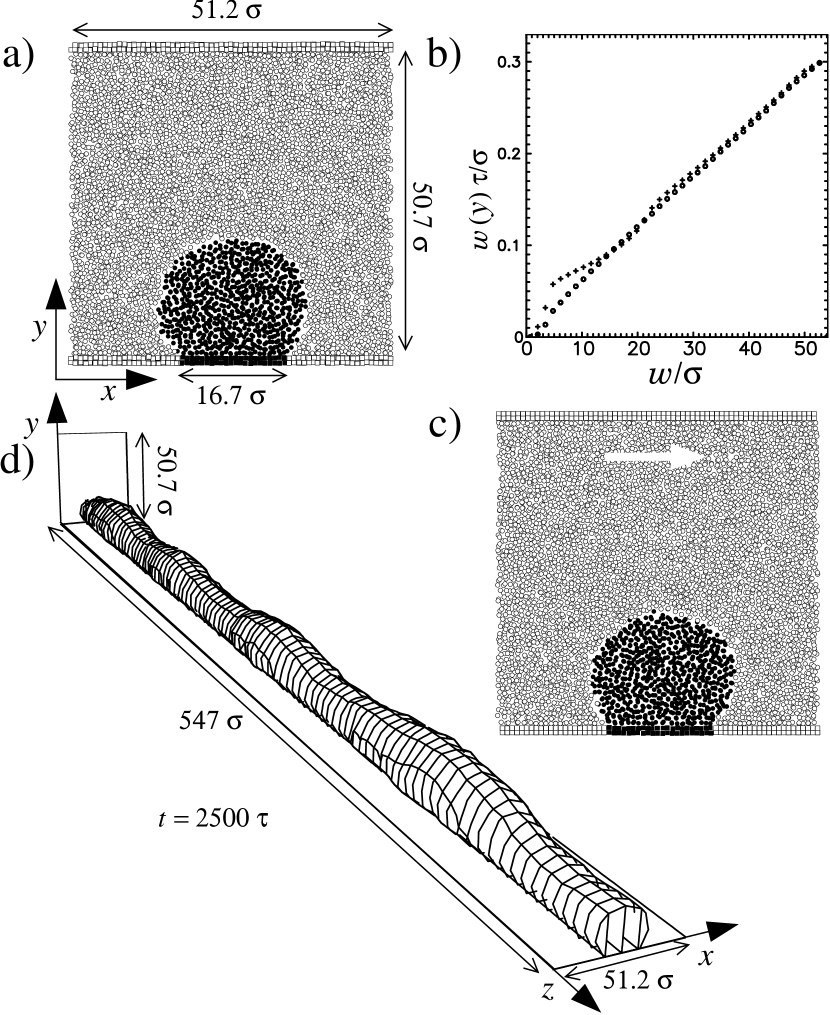
After a short equilibration period the inner liquid occupies a roughly cylindrical region pinned on one side to the wetting stripe (see Fig. 4(a)). We note that the liquid-liquid interface is much smoother than the previously studied liquid-vapor interfaces above wetting stripes Koplik et al. (2006). If the upper solid wall is moved parallel to the stripe, a two-fluid Couette flow results. Velocity profiles in two different vertical slabs parallel to the -plane are shown in Fig. 4(b). The velocities are averaged over the slab width of and the full system length, and a time interval of , with and the atom mass . On the sides of the simulation box, where only the outer liquid and the non-wetting solid are present, the profile (o) varies linearly aside from a weak bending near the walls. In the center of the simulation box the velocity (+) shows some additional deviation from linearity in the inner liquid region. There is liquid-liquid interfacial slip (as expected for the strongly immiscible liquids used here Koplik and Banavar (2006)) and some pinning behavior at the wetting stripe. In both cases, the velocity near both the stationary and moving wall exhibits a no-slip behavior, although extrapolations of the velocity profile from the interior of the channel would give rise to an apparent slip.
Under these circumstances the anchoring of the inner liquid at the wetting stripe is very stable, and we have observed that the inner liquid remains atop the stripe even if the forcing occurs at oblique angles. As an extreme example, if the top plate moves in the -direction with the same velocity as above, the snapshot of the atomic positions in Fig. 4(c) shows the inner fluid to be only modestly displaced to the side. However, in general, the interfacial shape is not stable, because the configuration is subject to a surface tension driven instability as long as the channel is long enough and filled to more than a contact angle Koplik et al. (2006). In that case, a periodic surface undulation develops, as shown in Fig. 4(d), which eventually leads to propagating liquid pearls.
In order to discuss the applicability of our concept (see Fig. 1), we estimate the throughput in a potential device. One prominent application is handling biological fluids which contain DNA fragments with a radius of gyration of about nm. We therefore consider a channel width and a plate spacing mm. These are dimensions already considered for chemical channels in slit pores Lam et al. (2002). Modern miniature hard disks (so-called Microdrives with a storage capacity of up to 8 GB) have a disk radius (see Fig. 1(b)) of about one centimeter and rotate at (see, e.g., Hitachi Global Storage Technologies http://www.hgst.com). The whole device has a size of so that building on this technology might lead to microfluidic devices of similar dimensions. For and the relative velocity of the discs at their perimeter is and the shear rate is . Assuming contact angles at the channel edges and that the viscosities of the two fluids are equal Eq. (4) renders an apex velocity .
In an inertia-driven situation the velocity at the surface of a planar film of thickness driven parallel to the substrate surface can be used as an order of magnitude estimate for the apex velocity with the mass density of the inner fluid and the acceleration . Thus for and an apex velocity requires an acceleration of . Such accelerations can be achieved with centrifugal forces at a radius of at as compared with a spin coater with , a turbo pump with , and a dentist’s drill with .
In order to assure laminar flow, the Reynolds number has to be small, both in the channel and in the oil. With the values for water one has in the channel. The relevant length scale for the oil is and the velocity scale is so that for and one obtains a similarly low Reynolds number for the outer liquid, leading to laminar flow.
Viscous heating of the oil is a possible concern. For the parameters discussed above, the power input into the device is of the order of so that cooling of the device is not expected to be a problem.
In summary, we propose to drive flow in open microfluidic systems by shear in a covering liquid of equal or higher viscosity, e.g., water filled channels covered with oil. As a positive side effect, the oil prevents evaporation. The analysis of the Stokes flow for channels filled to a contact angle at the channel edges shows (see Fig. 3) how increasing the viscosity of the covering liquid leads to an enhanced channel throughput for the same shear rate in the covering liquid. Fig. 3 also shows how, in the case that the covering liquid and the liquid in the channel have the same viscosity, the efficiency of the shear driving increases with increasing filling level. This observation is in agreement with the corresponding one in body force driven systems Koplik et al. (2006). Our MD simulations have encouragingly explored the potential to miniaturize the concept of shear driving down to the nano-scale.
Typical shear driven microfluidic devices might consist of two small discs rotating relative to each other. One or both of the discs can have a pattern of hydrophilic stripes on their hydrophobic surface. We discus how with available technology such a device can be built with the size of a miniature hard disc, i.e., a few centimeters wide and long and a few millimeters thick.
As expected, for a contact angle larger than we observe a surface tension driven pearling instability similar to the Rayleigh-Plateau instability as discussed in detail for body force driven systems Koplik et al. (2006). In MD simulations of a liquid completely wetting () a strip embedded into a non-wetting substrate () the liquid on the channel did not detach from the channel even if the shear was not aligned with the channel direction. The issue of the shear rate at which the liquid detaches from the channel is related to studies of moving droplets with contact angle hysteresis Dimitrakopoulos and Higdon (1997, 1998).
Our analysis suggests a significant application potential for shear driven open microfluidic systems, accompanied by further theoretical and experimental research.
Acknowledgements.
We thank P. Dimitrakopoulos for fruitful discussions. M.R. acknowledges financial support from the priority program SPP 1164 “Micro and Nano Fluidics” of the Deutsche Forschungsgemeinschaft under grant number RA 1061/2-1. J.K. is supported in part by the NASA Exploration Systems Mission Directorate. Computational resources were provided by the NASA Advanced Supercomputing Division at the Ames Research Center.References
- Giordano and Cheng (2001) N. Giordano and J.-T. Cheng, J. Phys.: Condens. Matter 13, R271 (2001).
- Mitchell (2001) P. Mitchell, Nature Biotech. 19, 717 (2001).
- Stone and Kim (2001) H. A. Stone and S. Kim, AIChE J. 47, 1250 (2001).
- Gustafsson et al. (2003) M. Gustafsson, D. Hirschberg, C. Palmberg, H. Jörnvall, and T. Bergman, Anal. Chem. 76, 345 (2003).
- Darhuber et al. (2001) A. A. Darhuber, S. M. Troian, and W. W. Reisner, Phys. Rev. E 64, 031603 (2001).
- Gau et al. (1999) H. Gau, S. Herminghaus, P. Lenz, and R. Lipowsky, Science 283, 46 (1999).
- Dietrich et al. (2005) S. Dietrich, M. N. Popescu, and M. Rauscher, J. Phys.: Condens. Matter 17, S577 (2005).
- Koplik et al. (2006) J. Koplik, T. S. Lo, M. Rauscher, and S. Dietrich, Phys. Fluids 18, 032104 (2006).
- Srinivasan et al. (2004) V. Srinivasan, V. K. Pamula, and R. B. Fair, Lab on a Chip 4, 310 (2004).
- Zeng and Korsmeyer (2004) J. Zeng and T. Korsmeyer, Lab on a Chip 4, 265 (2004).
- Farahi et al. (2004) R. H. Farahi, A. Passian, T. L. Ferrell, and T. Thundat, Appl. Phys. Lett. 85, 4237 (2004).
- Kotz et al. (2004) K. T. Kotz, K. A. Noble, and G. W. Faris, Appl. Phys. Lett. 85, 2658 (2004).
- Guttenberg et al. (2005) Z. Guttenberg, H. Müller, H. Habermüller, A. Geisbauer, J. Pipper, J. Felbel, M. Kielpinski, J. Scriba, and A. Wixforth, Lab on a Chip 5, 308 (2005).
- Abbott et al. (1999) S. Abbott, J. Ralston, G. Reynolds, and R. Hayes, Langmuir 15, 8923 (1999).
- Zhao et al. (2002) B. Zhao, J. S. Moore, and D. J. Beebe, Anal. Chem. 74, 4259 (2002).
- Seemann et al. (2005) R. Seemann, M. Brinkmann, E. J. Kramer, F. F. Lange, and R. Lipowsky, PNAS 102, 1848 (2005).
- Allen and Tildesley (1987) M. P. Allen and D. J. Tildesley, Computer Simulation of Liquids (Clarendon Press, Oxford, 1987).
- Frenkel and Smit (2002) D. Frenkel and B. Smit, Understanding Molecular Simulation (Academic Press, San Diego, 2002), 2nd ed.
- Koplik and Banavar (1995) J. Koplik and J. R. Banavar, Phys. Fluids 7, 3118 (1995).
- Koplik and Banavar (2006) J. Koplik and J. R. Banavar, Phys. Rev. Lett. 96, 044505 (2006).
- Lam et al. (2002) P. Lam, K. J. Wynne, and G. E. Wnek, Langmuir 18, 948 (2002).
- Dimitrakopoulos and Higdon (1997) P. Dimitrakopoulos and J. J. L. Higdon, J. Fluid Mech. 336, 351 (1997).
- Dimitrakopoulos and Higdon (1998) P. Dimitrakopoulos and J. J. L. Higdon, J. Fluid Mech. 377, 189 (1998).