Science, Vol.313, p.499, 2006
Violation of Kirchhoff’s Laws for a Coherent RC Circuit
Abstract
What is the complex impedance of a fully coherent quantum resistance-capacitance (RC)circuit at GHz frequencies in which a resistor and a capacitor are connected in series? While Kirchhoff’s laws predict addition of capacitor and resistor impedances, we report on observation of a different behavior. The resistance,here associated with charge relaxation, differs from the usual transport resistance given by the Landauer formula. In particular, for a single mode conductor, the charge relaxation resistance is half the resistance quantum, regardless of the transmission of the mode. The new mesoscopic effect reported here is relevant for the dynamical regime of all quantum devices.
For a classical circuit, Kirchhoff’s laws prescribe the addition of resistances in series. Its failure has been a central issue in developing our understanding of electronic transport in mesoscopic conductors. Indeed, coherent multiple electronic reflections between scatterers in the conductor were found to make the conductance non-local Landauer57 ; Landauer70 . A new composition law of individual scatterer contribution to resistance was found that led to the solution of the problem of electron localization Anderson81 and, later, to formulation of the electronic conduction in terms of scattering of electronic waves ButtImLandauer83 . Nonadditivity of series resistances, or of parallel conductances, nonlocal effects and negative four-point resistances GaoBO have been observed in a series of transport experiments at low temperature, where phase coherence extends over the mesoscopic scale Review1 ; Review2 . It is generally accepted that the conductance of a phase-coherent quantum conductor is given by the Landauer formula and its generalization to multi-lead conductors ButtLand , which relate the conductance to the transmission of electronic waves by the conductance quantum . But, how far is this description robust at finite frequency where conductance combines with nondissipative circuit elements such as capacitors or inductors ? Are there significant departures from the dc result ? The question is important, as recent advances in quantum information highlight the need for fast manipulation of quantum systems, in particular quantum conductors. High frequency quantum transport has been theoretically addressed, showing that a quantum RC circuit displays discrepancies with its classical counterpart Buttiker93 ; Pretre96 .

It was shown that a counter-intuitive modification of the series resistance lead to the situation in which the resistance is no longer described by the Landauer formula and does not depend on transmission in a direct way Buttiker93 ; Pretre96 . Instead it is directly related to the dwell time of electrons in the capacitor. Moreover, when the resistor transmits in a single electronic mode, a constant resistance was found, equal to the half-resistance quantum , i.e., it was not transmission-dependent. This resistance, modified by the presence of the coherent capacitor, was termed a ”charge-relaxation resistance” to distinguish it from the usual dc resistance, which is sandwiched between macroscopic reservoirs and described by the Landauer formula. The quantum charge-relaxation resistance, as well as its generalization in nonequilibrium systems, is an important concept that can be applied to quantum information. For example, it enters into the problem of quantum-limited detection of charge qubits Pilgram Clerk , in the study of high-frequency-charge quantum noise ChargeNoise1 ; ChargeNoise2 ; ChargeNoise3 , or in the study of dephasing of an electronic quantum interferometer Seelig . In molecular electronics, the charge relaxation resistance is also relevant to the THz frequency response of systems such as carbon nanotubesBurke .
We report on the observation and quantitative measurement of the quantum charge-relaxation resistance in a coherent RC circuit realized in a two-dimensional electron gas (2DEG) (see Fig.1A). The capacitor is made of a macroscopic metallic electrode on top of a 2DEG submicrometer dot defining the second electrode. The resistor is a quantum point contact (QPC) connecting the dot to a wide 2DEG macroscopic reservoir. We address the coherent regime in which electrons emitted from the reservoir to the dot are backscattered without loss of coherence. In this regime, we have checked the prediction made in refs.Buttiker93 ; Pretre96 that the charge-relaxation resistance is not given by the Landauer formula resistance but instead is constant and equals , as the QPC transmission is varied. Note that we consider here a spin-polarized regime and that the factor is not the effect of spin, but a hallmark of a charge-relaxation resistance. When coherence is washed out by thermal broadening, the more conventional regime pertaining to dc transport is recovered. The present work differs from previous capacitance measurements where, for spectroscopic purpose, the dot reservoir coupling was weak and the ac transport regime was incoherent Ashoori92a ; Ashoori92b . As a consequence, although quantum effects in the capacitance were observable, the quantum charge-relaxation resistance was not accessible in these earlier experiments.
At zero temperature in the coherent regime and when a single mode is transmitted by the QPC, the mesoscopic RC circuit is represented by the equivalent circuit of Fig.1B Buttiker93 ; Pretre96 . The geometrical capacitance is in series with the quantum admittance connecting the ac current flowing in the QPC to the ac internal potential of the dot:
| (1) |
The nonlocal quantum impedance behaves as if it were the series addition of a quantum capacitance with a constant contact resistance . is associated with the local density of state of the mode propagating in the dot, taken at the Fermi energy. The striking effect of phase coherence is that the QPC transmission probability affects the quantum capacitance (see Eq.4) but not the resistance. The total circuit admittance is simply :
| (2) |
where is the electrochemical capacitance. In the incoherent regime, both resistance and quantum capacitance vary with transmission. The dot forms a second reservoir and the electrochemical capacitance is in series with the QPC resistance . In particular, when the temperature is high enough to smooth the capacitor density of states, the Landauer formula is recovered.
Several samples have been measured at low temperatures, down to 30 mK, which show analogous features. We present results on two samples made with 2DEG defined in the same high-mobility GaAsAl/GaAs heterojunction, with nominal density m-2 and mobility V-1m2s-1. A finite magnetic field ( T) is applied, so as to work in the ballistic quantum Hall regime with no spin degeneracy SOM .
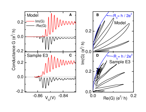
The real and imaginary parts of the admittance and as a function of QPC gate voltage at the opening of the first conduction channel are shown in Fig.2C. On increasing , we can distinguish three regimes. At very negative V, the admittance is zero. Starting from this pinched state, peaks are observed in both and . Following a maximum in the oscillations, a third regime occurs where oscillates nearly symmetrically about a plateau while the oscillation amplitude decreases smoothly. Simultaneously, peaks in quickly disappear to vanish in the noise.
Comparing these observations with the results of refs.Buttiker93 ; Pretre96 ,using a simplified one-dimensional (1D) model for with one conduction mode and a constant energy level spacing in the dot Gabelli06 , the simulation (Fig.2A) shows a striking similarity to the experimental conductance traces in Fig.2C. In this simulation, determines the transmission but also controls linearly the 1D dot potential. The transmission is chosen to vary with according to a Fermi-Dirac-like dependence appropriate to describe QPC transmission Butt90 . This model can be used to get a better understanding of the different conductance regimes. Denoting and the amplitude reflection and transmission coefficients of the QPC (, ), we first calculate the scattering amplitude of the RC circuit:
| (3) |
where is the Fermi energy relative to the dot potential and is the phase accumulated for a single turn in the quantum dot. The zero-temperature quantum capacitance is then given by:
| (4) |
Therefore, exhibits oscillations when the dot potential is varied. When , these oscillations vanish and . As reflection increases, oscillations are growing with maxima and minima . For strong reflection, Eq 4 gives resonant Lorentzian peaks with an energy width given by the escape rate of the dot. However, at finite temperature, the conductance in equation (1) has to be thermally averaged to take into account the finite energy width of the electron source so that :
| (5) | |||
where is the Fermi-Dirac distribution. Again, the nonlocal admittance behaves as if it were the serial association of a charge-relaxation resistance and a capacitance that we still denote . In the weak transmission regime (), when , equation (5) yields thermally broadened capacitance peaks with
| (6) |
where denotes the energy distance to a resonant dot level. Note that these capacitance peaks do not depend on the dot parameters and can be used as a primary thermometer. Similar but transmission-dependent peaks are predicted in the inverse resistance
| (7) |
This result is reminiscent of the thermally broadened resonant tunneling conductance for transport through a quantum dot. A consequence of the finite temperature is the fact that the resistance is no longer constant. This thermally-induced divergence of at low transmission restores a frequency-dependent pinch-off for , as can be seen in both model and experiment in Figs.2A.C. As mentioned above, for , the quantum dot looks like a reservoir and the Landauer formula is recovered.
The coherent and the thermally broadened regimes are best demonstrated in the Nyquist representation versus of the experimental data in Fig.2D. This representation allows to easily distinguish constant resistance from constant capacitance regimes, as they correspond to circles respectively centered on the real and imaginary axis. Whereas, for low transmission, the Nyquist diagram strongly depends on transmission, the conductance oscillations observed in Fig.2C collapse on a single curve in the coherent regime. Moreover this curve is the constant circle. By contrast, admittance peaks at low transmission correspond to a series of lobes in the Nyquist diagram, with slopes increasing with transmission in qualitative agreement with Eqs.6 and 7. These lobes and the constant regime are well reproduced by the simulations in Fig.2B. Here, the value of and the electronic temperature are deduced from measurement. In our experimental conditions, the simulated traces are virtually free of adjustable parameters as .
It is important to note that in a real system, the weak transmission regime is accompanied by Coulomb blockade effects that are not taken into account in the above model. In the weak transmission regime and , using an elastic co-tunneling approach Averin92 ; Glattli93 , we have checked that there is no qualitative change except for the energy scale that now includes the charging energy so that is replaced by +=. At large transmission, the problem is nonperturbative in tunnel coupling and highly nontrivial. Calculations of the thermodynamic capacitance exist Matveev ; Glazman98 ; Brouwer05 , but at present, no comprehensive model is available that would include both charge-relaxation resistance and quantum capacitance for finite temperature and/or large transmission.
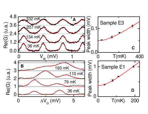
Calibration of our admittance measurements is a crucial step toward extracting the absolute value of the constant charge-relaxation resistance. As at GHz frequencies, direct calibration of the whole detection chain is hardly better than 3dB, we shall use here an indirect, but absolute, method, often used in Coulomb blockade spectroscopy, that relies on the comparison between the gate voltage width of a thermally broadened Coulomb peak () and the Coulomb peak spacing (). From this, an absolute value of can be obtained. The real part of the admittance of Sample E3 is shown as a function of the dc voltage at the counter-electrode, for a given low transmission (Fig.3A). A series of peaks with periodicity V are observed, with the peaks accurately fitted by Eq.7. Their width, proportional to the electronic temperature , is plotted versus the refrigerator temperature (see Fig.3C). When corrected for apparent electron heating arising from gaussian environmental charge noise, and if we assume , the energy calibration of the gate voltage yields and the amplitude of the conductance plateau in Fig.2. A similar analysis is done in Fig.3, B and D, for sample E1 using to control the dot potential. Here peaks are distorted because of a transmission-dependent background and show a larger periodicity mV, which reflects the weaker electrostatic coupling to the 2DEG.
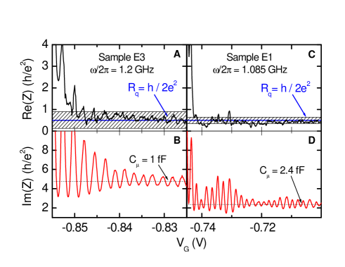
Finally, after numerical inversion of the conductance data, we can separate the complex impedance into the contributions of the capacitance, , and the relaxation resistance . The results in Fig.4 demonstrate deviations from standard Kirchhoff’s laws : the charge-relaxation resistance remains constant in the regime where the quantum capacitance exhibits strong transmission-dependent oscillations; this constant value equals, within experimental uncertainty, half the resistance quantum as prescribed by theory Buttiker93 ; Pretre96 . In the weak transmission regime, the Landauer formula is recovered because of thermal broadening, and diverges as it does in the dc regime. Furthermore, additional measurements at prove that the classical behavior is indeed recovered in the whole transmission range whenever .
In conclusion, we have experimentally shown that the series
association of a quantum capacitor and a model quantum resistor
leads to a violation of the dynamical Kirchhoff’s law of impedance
addition. In the fully coherent regime, the quantum resistor is no
longer given by the Landauer formula but by the half-quantized
charge-relaxation resistance predicted in
Ref.Buttiker93 ; Pretre96 .
The LPA is the CNRS-ENS UMR8551 associated with universities Paris 6
and Paris 7. The research has been supported by AC-Nanoscience,
SESAME grants and ANR-05-NANO-028.
References
- (1) R. Landauer, IBM J. Res. Dev. 1, 233 (1957).
- (2) R. Landauer, Phil. Mag. 21, 863 (1970).
- (3) P.W. Anderson, Phys. Rev. B 23, 4828 (1981).
- (4) M. Büttiker, Y. Imry, R. Landauer, S. Pinhas, Phys. Rev. B. 31, 6207 (1985).
- (5) B. Gao, A. Komnik, R. Egger, D.C. Glattli, A. Bachtold, Phys. Rev. Lett. 92, 216804 (2004).
- (6) see for a review, S. Datta, Electronic Transport in Mesoscopic Systems, Cambridge University Press, Cambridge, (1997).
- (7) see for a review, Y Imry, Introduction to Mesoscopic Physics, Oxford University Press, Oxford (1997).
- (8) M. Büttiker, Phys. Rev. Lett. 57, 17611764 (1986)
- (9) M. Büttiker, A. Prêtre, H. Thomas, Phys. Rev. Lett. 70, 4114 (1993).
- (10) A. Prêtre, H. Thomas, M. Büttiker, Phys. Rev. B. 54, 8130 (1996).
- (11) S. Pilgram, M. Büttiker, Phys. Rev. Lett. 89, 200401 (2002).
- (12) A.A. Clerk, S.M. Girvin, A.D. Stone, Phys. Rev. B. 67, 165324 (2003).
- (13) M. Büttiker, H. Thomas, A. Prêtre, Phys. Lett. A 180, 364 (1993).
- (14) Ya. M. Blanter, M. Büttiker, Phys. Rep. 336, 1 (2000).
- (15) F.W.J. Hekking, J.P. Pekola, Phys. Rev. Lett. 96, 056603 (2006).
- (16) G. Seelig, S. Pilgram, A. N. Jordan, M. Büttiker, Phys. Rev. B. 68, 161310 (2003).
- (17) P. J. Burke, IEEE T Nanotechnol 2 (1), 55 (2003).
- (18) R. C. Ashoori et al., Phys. Rev. Lett. 68, 3088 (1992).
- (19) R. C. Ashoori et al., Phys. Rev. Lett. 71, 613 (1992).
- (20) Materials and methods are available as supporting material on Science Online.
- (21) J. Gabelli, thesis, Université Pierre et Marie Curie, Paris, 2006; On line access at (http://tel.ccsd.cnrs.fr/tel-00011619).
- (22) M. Büttiker, Phys. Rev. B 41, 7906 (1990).
- (23) D.V. Averin, Y. Nazarov, Single charge tunneling, chap.6, NATO-ASI series B, Vol.294, Plenum, New York, 1992.
- (24) D.C. Glattli, Physica B 189, 88 (1993).
- (25) K.A. Matveev, Phys. Rev. B.51 , 1743 (1995).
- (26) L.I. Glazman, I.L. Aleiner, Phys. Rev. B. 57, 9608 (1998).
- (27) P.W. Brouwer, A. Lamacraft, K. Flensberg Phys. Rev. B. 72, 075316 (2005), and references therein.