Refraction of shear zones in granular materials
Abstract
We study strain localization in slow shear flow focusing on layered granular materials. A heretofore unknown effect is presented here. We show that shear zones are refracted at material interfaces in analogy with refraction of light beams in optics. This phenomenon can be obtained as a consequence of a recent variational model of shear zones. The predictions of the model are tested and confirmed by 3D discrete element simulations. We found that shear zones follow Snell’s law of light refraction.
pacs:
47.57.Gc, 45.70.-n, 83.80.Fg, 83.50.Ax, 42.25.GyThe motion of granular materials, such as sand, is difficult to predict, as they behave neither like elastic solids nor like normal fluids. When they yield under stress and start flowing, the material consists of large, almost solid parts, and the relative motion is confined to narrow regions between them, called shear zones or shear bands Mueth et al. (2000); Fenistein and van Hecke (2003); GDR_MiDi (2004). Shear zones represent material failure and therefore play a crucial role in geophysics (geological faults), in engineering (building foundations) and in industrial processes. It is an important problem of these fields to predict where the failure takes place. This is a difficult task for those shear zones which arise in the bulk of the material far from the confining walls Fenistein and van Hecke (2003); Fenistein et al. (2004); Luding (2004); Cheng et al. (2006); Unger et al. (2004); Török et al. .
Nature often stratifies granular media, i.e. different materials are deposited in distinct layers. We study here the question what effect such inhomogeneities have on shear zones. Based on a recent theory and computer simulations we show that shear zones are refracted when they pass through the interface between different granular layers. Moreover, the angle of refraction obeys a law analogous to Snell’s law of light refraction which reveals an unexpected analogy between granular media and geometric optics. The effect of refraction presented here influences the position of shear zones in various kinds of materials including powders, sand, soil and rock layers providing implications on the behavior of geological faults Schultz and Siddharthan (2005); Scott (1996).
Recently the variational principle of minimum dissipation was successfully applied Unger et al. (2004); Török et al. to describe the non-trivial shape of the shear zone in a homogeneous granular material which is sheared in a modified Couette cell Fenistein et al. (2004); Luding (2004); Cheng et al. (2006). Minimum rate of energy dissipation is a widely applied selection principle Jaynes (1980) to determine which steady states are realized in nature. When applying this principle to the cylindrical geometry of the modified Couette cell Unger et al. (2004), not only the non-trivial position of the shear zone could be calculated without any fitting parameter, but new, closed shear zones were predicted which were discovered also in experiments Fenistein et al. (2006) and simulations Cheng et al. (2006). In the following, a so far unknown but measurable effect will be derived from the same principle. It concerns the shape of shear zones in layered granular materials.
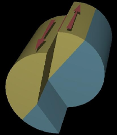
This phenomenon can be understood best, if the side effects of gravity and curved shearing are absent. Therefore a long cylindrical container is considered, which is cut along its axis into two halves (Fig. 1a). (In computer simulations periodic boundary conditions in the axial direction are applied.) The container is completely filled with two granular materials having different frictional properties. They are separated by a planar interface parallel to the axis, but at an angle to the cut of the container. The system is sheared quasi-statically GDR_MiDi (2004) by moving the two halfs of the cylinder wall slowly parallel to the axis in opposite directions. This creates a shear zone starting and ending where the container wall is cut. In order to find the shape of the zone in between we apply the principle of minimum dissipation. This, in zero width approximation Unger et al. (2004), leads to the following variational problem (explained below):
| (1) |
Here the local rate of energy dissipation is integrated over the whole surface of the shear zone. The shear zone is regarded as being infinitely thin, outside the shear zone no deformation and no dissipation takes place. The local dissipation rate per unit area is obtained by the sliding velocity between the two sides of the shear zone times the shear stress . The parameters and denote the overall pressure in the system and the coarse grained effective friction coefficient GDR_MiDi (2004). The effective friction has different values for the two materials while and are taken constant for our setup 111By contrast, and depend strongly on the position in the modified Couette cell. This is caused by gravity (for ) and by curved shearing (for ) Unger et al. (2004). For clarity, these effects are avoided in our case.. The surface that minimizes the total rate of dissipation provides the shape of the shear zone. This means that the system yields along the surface where it has the least resistance against the external shear.
The system is translation invariant along the axis, therefore the above surface integral is reduced to a line integral. We have to find the path (cross section of the shear zone) which connects two fixed points and along which the integral of is minimal. This problem has exactly the form of Fermat’s principle of geometric optics where the effective friction plays the role of the index of refraction. It is known that Fermat’s principle of the shortest travel time leads to refraction of light beams therefore one can expect a similar phenomenon of refraction also for shear zones.
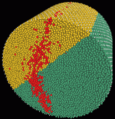
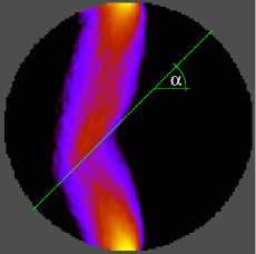
In order to check this prediction we carried out computer simulations of frictional and hard spherical beads (Fig. 1b). Based on a standard discrete element method (DEM) Jean (1999); Brendel et al. (2004) the motion of each bead is determined by Newton’s equation. This grain-level dynamics leads to a collective steady state flow where we measure the coarse-grained velocity field. The coarse-grained velocities are parallel to the cylinder axis. The local strain rate, which is calculated from the velocity field, corresponds to pure shear deformation (without volumetric strain). The spatial distribution of the magnitude of the shear rate is shown in Fig. 1c. As predicted, the arising shear zone departs from the cut plane and its direction is changed significantly at the material interface (Fig. 1b, c). Note, that the shear zone we obtained is quite wide relative to the system size. The relative width becomes smaller for larger systems Fenistein et al. (2004) which, however, would demand also a computational effort out of reach. Still, the effect of refraction is clearly shown.
The analogy with light refraction provides quantitative predictions that can be measured in numerical and real experiments. Fermat’s principle indicates that shear zones have to follow Snell’s law of light refraction which will be tested here by DEM simulations. In order to do so we characterize the behavior of the shear zone by two angles and which are analogous to the incident and refractive angles used in geometric optics. These are defined with the help of the shear deformation (Fig. 1c) as follows: first, the refraction point is identified as the point along the interface where the local shear rate has its maximum. Then the refraction point is connected to the starting and ending points of the shear zone by straight lines. Thus the direction of the shear zone on each side of the interface is determined. These directions provide the angles and with respect to the normal of the interface. Another angle, which is an important input parameter of the shear test, is the tilt angle of the interface between the normal of the cut plane and the interface (Fig. 1c). For various values of we measured and . If the interface is perpendicular to the cut plane () no refraction was observed, however, as is increased the refraction of the shear zone becomes more and more pronounced.
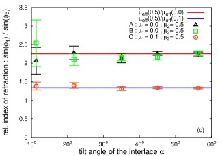
If we apply Snell s law to our case it indicates that, no matter how the angles and are changed, the ratio of and has to be independent of the tilt angle . Furthermore it is expected that this ratio can be expressed by the effective frictions:
| (2) |
First we report the influence of observed in simulations. We used materials that contained hard spheres of radii distributed uniformly between and . This polydispersity was needed to avoid shear induced crystallization Tsai et al. (2003). In order to control the frictional properties of the materials we varied the value of the microscopic friction which is the friction coefficient at the particle-particle contacts. It is important to note that the microscopic friction and the effective friction are not the same although they are closely related as we will see later. We simulated three systems called , and . The total number of particles was for system and for systems and . For each case the shear cell was filled with two materials with microscopic frictions and . For systems and and while for system and . For all systems the radius of the container was approximately .
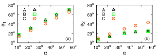
The influence of the tilt angle of the interface is presented in Fig. 2. The computer simulations show that and vary strongly but remains constant for a wide range of the angle . This ratio seems to depend only on the materials in which the shear zone was created, in full agreement with the theoretical considerations.
Next we deal with the role of the effective friction. It is known that if a dense noncohesive granular material is sheared then after a short transient Craig (2004) it reaches a well defined resistance against shear deformation provided the flow is slow enough (quasistatic shear). Thus a material parameter, the effective friction coefficient, can be defined which turns out to be independent of the preparation history, the actual shear rate and the confining pressure GDR_MiDi (2004); Radjai and Roux (2004). The effective friction is given by the shear stress divided by the normal stress, both measured in the plane along which the shear deformation takes place.
The quantity is not a microscopic input parameter of the computer simulation, thus the question arises what values has for the materials that appeared in systems , and . This can be deduced from simulations which are independent of the previous refraction tests: we put the same materials into a 3D rectangular box under plane shear GDR_MiDi (2004) measure the components of the stress tensor Christoffersen et al. (1981) and calculate the value of . In this way we achieve a calibration curve that provides a one to one correspondence between microscopic and effective friction, see Fig. 3.

With that we arrived to a point where we can make quantitative statements about the extent of the refraction based on Snell’s law. E.g. for system , with help of the prescribed values of and , the ratio can be calculated and compared to the data recorded in the refraction test. This is done in Fig. 2 for systems , and . A surprisingly good agreement is found between the predicted and measured values which holds for all systems and for various tilt angles of the interface. This is our main result.
Dealing with shear localization in layered granular materials we investigated the predictions of a recent variational model and compared them to computer simulations. The results of the present work convey two messages. First, we gave verification of the variational approach to granular shear flows. We tested the model in a new situation and, according to the numerical data, it gave an excellent description of the behavior of the shear zones. Second, an interesting analogy between granular flow and geometric optics is revealed. We showed that shear zones are refracted at material interfaces similarly to light beams. The phenomenon presented here should be accessible by experiments.
We are grateful to J. Kertész and D.E. Wolf for their support and help. Support by grant OTKA T049403 and by the G.I.F. research grant I-795-166.10/2003 is acknowledged.
References
- Mueth et al. (2000) D. M. Mueth, G. F. Debregeas, G. S. Karczmar, P. J. Eng, S. R. Nagel, and H. M. Jaeger, Nature 406, 385 (2000).
- Fenistein and van Hecke (2003) D. Fenistein and M. van Hecke, Nature 425, 256 (2003).
- GDR_MiDi (2004) GDR_MiDi, Eur. Phys. J. E 14, 341 (2004).
- Fenistein et al. (2004) D. Fenistein, J. W. van de Meent, and M. van Hecke, Phys. Rev. Lett. 92, 094301 (2004).
- Luding (2004) S. Luding, in The Physics of Granular Media (Wiley-VCH, Weinheim, 2004), pp. 299–324.
- Cheng et al. (2006) X. Cheng, J. B. Lechman, A. Fernandez-Barbero, G. S. Grest, H. M. Jaeger, G. S. Karczmar, M. E. Möbius, and S. R. Nagel, Phys. Rev. Lett. 96, 038001 (2006).
- Unger et al. (2004) T. Unger, J. Török, J. Kertész, and D. E. Wolf, Phys. Rev. Lett. 92, 214301 (2004), cond-mat/0401143.
- (8) J. Török, T. Unger, J. Kertész, and D. E. Wolf, cond-mat/0607162 (http://www.arxiv.org/abs/cond-mat/0607162), accepted in PRE.
- Schultz and Siddharthan (2005) R. A. Schultz and R. Siddharthan, Tectonophysics 411, 1 (2005).
- Scott (1996) D. R. Scott, Nature 381, 592 (1996).
- Jaynes (1980) E. T. Jaynes, Ann. Rev. Phys. Chem. 31, 579 (1980).
- Fenistein et al. (2006) D. Fenistein, J.-W. van de Meent, and M. van Hecke, Phys. Rev. Lett. 96, 118001 (2006).
- Jean (1999) M. Jean, Comput. Methods Appl. Mech. Engrg. 177, 235 (1999).
- Brendel et al. (2004) L. Brendel, T. Unger, and D. E. Wolf, in The Physics of Granular Media (Wiley-VCH, Weinheim, 2004), pp. 325–343.
- Tsai et al. (2003) J. C. Tsai, G. A. Voth, and J. P. Gollub, Phys. Rev. Lett. 91, 064301 (2003).
- Craig (2004) R. F. Craig, Craig’s soil mechanics (Spon Press, New York, 2004).
- Radjai and Roux (2004) F. Radjai and S. Roux, in The Physics of Granular Media (Wiley-VCH, Weinheim, 2004), pp. 165–187.
- Christoffersen et al. (1981) J. Christoffersen, M. M. Mehrabadi, and S. Nemat-Nasser, J. Appl. Mech. 48, 339 (1981).