Slippage of water past superhydrophobic carbon nanotube forests in microchannels
Abstract
We present in this letter an experimental characterization of liquid flow slippage over superhydrophobic surfaces made of carbon nanotube forests, incorporated in microchannels. We make use of a -PIV (Particule Image Velocimetry) technique to achieve the submicrometric resolution on the flow profile necessary for accurate measurement of the surface hydrodynamic properties. We demonstrate boundary slippage on the Cassie superhydrophobic state, associated with slip lengths of a few microns, while a vanishing slip length is found in the Wenzel state, when the liquid impregnates the surface. Varying the lateral roughness scale of our carbon nanotube forest-based superhydrophobic surfaces, we demonstrate that the slip length varies linearly with in line with theoretical predictions for slippage on patterned surfaces.
pacs:
68.08.-p,68.15.+e, 47.61.-k, 47.63.GdThe nature of the hydrodynamic boundary condition of a liquid past a solid surface has been actively revisited over the recent years, strongly motivated by the emergence of microfluidics and nanofluidics ref ; Squ05 . Downsizing leads to large surface-to-volume ratio, and the flow properties at the solid boundaries become a key factor in the understanding of the motion of liquids in ever smaller channels Squ05 . In this context the violation of the no-slip boundary condition (BC) and the existence of slippage of the fluid at the solid surface is a promising way to bypass the huge increase in hydrodynamic resistance that comes with miniaturization.
Slippage, usually quantified by a slip length , has been demonstrated on solvophobic surfaces, with a slip length of a few tens of nanometers BB ; ref ; Cot05 ; Joly06 ; Vino03 . Such values are obviously insufficient to modify the flow in channels with micrometer sizes and other specific solutions have to be proposed to benefit from slippage effects in microfluidics. Super-hydrophobic surfaces are promising in this context, since it has been recently predicted Cot and experimentally reported Roth05 that the associated “Fakir” effect (the so-called Cassie state) considerably amplifies slippage. This situation is achieved with highly rough hydrophobic surfaces: instead of entering this bidimensionnal hydrophobic porous medium, the liquid remains at the top of the roughness thus trapping some air in the interstices, and therefore leading to a very small liquid-solid contact area.
In the context of microfluidics, the challenge now consists in developping versatile methods to design such surfaces in microchannels with optimized flow properties. These have to deal with two conflicting constraints on the engineered surfaces: low friction –i.e. large slippage– and robustness of the Fakir effect against pressure induced impregnation. On the one hand, large slippage is achieved by minimizing the liquid-solid area together with maximizing the underlying lateral length scale of the roughness. Indeed, theoretical predictions show that the resulting effective slip length is mainly fixed by the roughness scale Stone ; Philip ; Cottheory ; cyb06 : , with a numerical factor (smaller than unity for typical surfaces). On the other hand, the stability of the Fakir (Cassie) state with respect to pressure variations fixes some restrictive conditions on the underlying roughness scale quere2002 : above an excess pressure of the order of (with the liquid-vapor surface tension), penetration of the liquid into the roughness occurs –Wenzel state–, and the benefits from the low friction Fakir state are lost. The potential applicability of lithographically designed patterned surfaces, with a surface lateral scale in the ten microns range is therefore limited by their low resistance to pressure Roth05 . While one would expect the increased robustness on nanoengineered surfaces to be achieved at the expense of their slippage properties, recent rheology measurements on nanopost superhydrophobic surfaces have reported slip lengths of tens of microns Choi in clear contrast with theoretical expectations Stone ; Philip ; Cottheory ; cyb06 and with the experimental results of Roth05 at larger (micrometric) scales. This surprising result would suggest that the underlying roughness does not limit the slip length for nanopatterned surfaces, as first expected. However the sensitivity of the rheological method used in Choi appears questionnable Boc06 , and it therefore points out the need for accurate experimental data to achieve a proper understanding of the role of the underlying roughness scale, from nano- to micro- patterned surfaces.
The purpose of the present work is precisely to provide accurate data allowing to understand the role of the roughness scale on the hydrodynamic properties of superhydrophobic surfaces. Taking benefit of recent advances in nanomaterials science we incorporated versatile composite surfaces in microchanels. We make use of recently developed surfaces covered with vertically aligned and densely spaced carbon nanotubes (CNT forests) Lau2003 ; EPL05 . Together with the existence of large contact angles (larger than ), the submicrometric lateral length scale achievable on these surfaces was shown to provide a robust Fakir state with respect to pressure EPL05 , with an intrusion pressure . More interesting in the present framework, is the ability provided by the method to achieve various lateral length scales in the submicron to microns range. Flows in the vicinity of such surfaces were then investigated using particle image velocimetry at the micron scale (-PIV) to probe the velocity profile in the microchannels with submicrometric resolution. Our measurements confirm that a low friction is achieved providing the interface lies in the Fakir state, and demonstrate that these low friction properties are indeed controlled by the lateral roughness scale, in agreement with theoretical considerations Cottheory ; cyb06 .
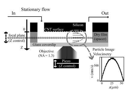
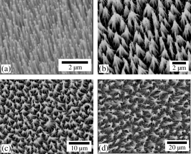
The experimental setup is shown in fig. 1. The CNT forests are obtained using Plasma Enhanced Chemical Vapor Deposition (PECVD), using the protocol previously described in Lau2003 ; EPL05 . The CNT forests are grown on a silicon substrate covered with a SiO2 layer and a thin film of Ni catalyst. This develops Ni islands through the sintering of the Ni film (after introduction in a furnace heated to 750∘C under 20 torr of hydrogen). Ammonia and then acethylene (C2H2) are introduced into the furnace to initiate the CNT growth. A dc discharge between the cathode and anode samples allows for directed growth. The depositions are carried out between 5 and 60 minutes in a stable discharge. Typical CNT forests grown through this process are characterised by a typical nanotube diameter between 50 and 100 nm, a nanotube inter-distance 100-250 nm, and micrometric lengths, as shown on Fig. 2(a). The nanotube lengths and inter-distance can be tuned by varying the deposition time and the thickness of the nickel layer.
To get a superhydrophobic behavior, the CNT forests are then functionalized using thiols in gas or liquid phase, after covering them with an anchoring thin gold layer (5 nm) by sputtering as described in EPL05 . While the gas phase functionalization leaves the CNT forest structure unchanged EPL05 , the functionalization in a liquid phase results in bundles of carbon nanotubes (see fig 2(b-d)), as a result from capillary adhesion during the evaporative drying of the functionalization solvent, ethanol Bico2004 ; EPL05 . Combined with the control of the nanotube density and length, this bundling process is used in the present study as a further way to tune the roughness lateral scale .
These CNT surfaces are embedded in a microfluidic setup (see fig. 1) featuring a microchannel of height 40-m, width mm and length cm. This microchannel is obtained by sandwiching a dry film resist that has a lithographic trench between a CNT covered silicon substrate and a microscope glass coverslip, following a recently introduced method Vulto05 . A pressure driven flow is set up by controlling inlet and outlet pressures in the range of -50 to 100 mbar with respect to the atmospheric pressure, while the pressure drop along the channel remains below 2 mbar. The working solution is deionized water seeded with fluorescent particles (500 nm in diameter), in volumetric concentration. The observation is made with a LEICA epifluorescent microscope, using a oil immersion large numerical aperture objective (NA=1.3) achieving a 700nm depth of field. An optical depth of 500nm is obtained for the measurement volume by thresholding on the intensity and then selecting the particles in focus. The velocity profile is measured using a standard -PIV technique, similar to that described in Joseph2005 , where further details can be found. Briefly, a scan in the vertical direction is provided using a piezotransducer with m step increments, allowing to measure the velocity profile in the whole microchannel. A time-delayed intensity cross correlation is performed in a mm window, and the computed velocity is averaged over 20 pairs of images for each -position of the piezo. We thus obtain eventually an averaged velocity in an imaged zone of . Typical velocity profiles (see fig. 1) present the characteristic parabolic shape associated with the pressure-driven Poiseuille flow.
The position of the CNT surface has been carefully determined. As in Joseph2005 , we take advantage of the presence of a few particles which unavoidably adsorb on surfaces [we only considered windows of observation where at least 3, and up to ten, of such beads are included]. The position of the surface is then determined by fitting the fluorescence intensity emitted by these beads with a lorentzian and by substracting the bead radius from the location of the maximum of the lorentzian. We have considered flows on surfaces in the Cassie state (with trapped air), but also on surfaces in the Wenzel state, where the CNT surfaces are impregnated. This latter behavior –impregnation of the surface roughness– occurs for a few devices at long times and is likely due to defects at the edges of the channel (as suggested by direct observation). These few devices therefore offer the opportunity to also study slippage in the Wenzel state. When the CNT surface is in the Cassie state, the liquid interface lies at the top of the nanotube bundles, to which adsorbed beads are therefore restricted, fixing thereby the effective solid-liquid interface. On the other hand, in the Wenzel state beads are distributed between the top and bottom of the nanotubes and the “effective” (solid-liquid) interface is in that case fixed at the mean position between the top and the bottom of the CNT. The CNTs present a length polydispersity, responsible for the uncertainty in the location of the liquid interface. This uncertainty is measured on each CNT surface and is typically of the order of nm, similar to the characteristic deviation in height of the grown CNT forests (see figs 2 and 3).
Fig. 3 shows a zoom of the water velocity profile measured in the vicinity of the liquid interface when the CNT surface is in the Cassie state. The two vertical dashed lines represent the uncertainty in the position of the liquid interface, as discussed above. As shown in this figure, the velocity profile does not vanish at the boundary and does exhibit slippage at the interface. This slippage can be accounted for by the standard Navier BC for the velocity field at the interface : is the slip length and can be interpreted as the extrapolated distance at which the velocity would vanish. Experimentally, is obtained by fitting the velocity profile using the Poiseuille prediction. For each surface, this procedure is repeated on about 5 measurement windows chosen in different locations at the CNT surface in the microchannel from which an averaged value and error bar are deduced for the slip length.
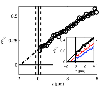
As mentioned above, the characteristics of the underlying CNT surfaces can be varied: the distance between bundles is mainly tuned by the length and density of the forest before functionalization in the liquid phase EPL05 . We have examined the flow behavior on surfaces with various lateral length scales , measured by computing the intensity autocorrelation of the top images of the SEM pictures. In the examined surfaces this typical lateral characteristic length of the roughness varied between m up to m. We have therefore measured the slip length on these surfaces using the procedure described above. Resulting flow profiles for the Cassie state are shown in the inset of fig. 3. The slippage increases with the roughness length scale as is summarized in fig. 4 where the measured average slip length is plotted against , the error bar corresponds to the dispersion in the measurements. We have also measured the slip length for different for systems in the Wenzel state. As shown in fig. 4, slippage is strongly reduced in the Wenzel state, due to the increased liquid-solid friction in the absence of trapped air in the CNT, in agreement with theoretical predictions Cottheory .
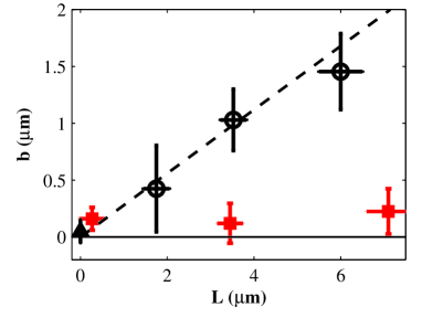
Our results point out the absence of slippage in the Wenzel sate and the direct, linear, dependence of the measured slip length on the CNT lateral roughness scale in the Cassie superhydrophobic state. This confirms recent theoretical predictions made for the effective slip length on superhydrophobic micro-structured surfaces Philip ; Stone ; Cottheory ; cyb06 . In the Cassie state, the liquid is in direct contact with the solid only through a small fraction () of the surface. At the hydrodynamic level, this composite surface leads to a spatially dependent BC with a no-slip BC on the fraction of real solid-liquid interface (with fraction ), while the remaining surface is characterized by a perfect slip BC () on the suspended liquid-vapor interface. At a qualitative level, the theoretical results can be summarized by stating that the effective slip length essentially saturates at the value fixed by the lateral scale of the roughness , . For instance a flow perpendicular to stripes yields Philip ; Stone showing a weak dependency on for feasible surfaces. In our case, the experimental surface is closer to an array of pillars. Since no analytical form is available in this case, we have extended our previous theoretical analysis of Ref. Cottheory to this geometry, showing that the main features of the effects described in Philip ; Stone ; Cottheory (for a surface made of stripes) are preserved for a pattern of pillars cyb06 . In particular, our predictions in this geometry are again summarized by , with a slowly varying , except very close to . This prediction is shown in fig. 4 to be in good agreement with experimental results, with a value of , corresponding to a constant value for of 0.15–0.2. The latter is reasonably consistent with the experimental value of estimated from the contact angle on the CNT surfaces () and the Cassie theory EPL05 . The slightly higher value of obtained in the slippage measurements may result from the random distribution of pillars, as opposed to the regular one used here in the theoretical description of slippage.
Finally the slip lengths we measure are substantially smaller than the ones reported recently in Choi using global rheological measurements (m for water). However, unlike the present -PIV method capable of submicrometric resolution Joseph2005 , the rheological setup lacks the sensitivity required to measure surface effects characterized by slippage in the micron range Boc06 . Our results moreover points out that the effect of the underlying roughness can not be overlooked in determining the slip length on such surfaces, therefore demonstrating that the gas cushion model used in Ref. Choi fails to interprete slippage on nanopatterned surfaces.
To conclude we have measured the surface hydrodynamic properties of superhydrophobic surfaces made of carbon nanotube carpets incorporated into microchannels. Such surfaces are shown to exhibit a no slip boundary condition in the Wenzel state and slip lengths of a few microns in the superhydrophobic (Cassie) state. Moreover, these slip lengths were found to vary linearly with the lateral roughness scale in agreement with theoretical predictions. For a microsystem with given experimental constraints (working pressure, dimensions), this now opens the possibility of designing optimized surfaces in terms of friction reduction and robustness.
We thank K. Stephan R. Ferrigno, S. Purcell and C. Barentin for their help during this work.
References
- (1) T. Squires, S. Quake, Rev. Mod. Phys. 77, 977 (2005).
- (2) E. Lauga, M. Brenner, H. Stone, Handbook of Experimental Fluid Dynamics (Springer, 2005).
- (3) J.L. Barrat, L. Bocquet, Phys. Rev. Lett. 82, 4671 (1999).
- (4) C. Cottin-Bizonne, B. Cross, A. Steinberger and E. Charlaix,Phys. Rev. Lett.,94, 056102 (2005).
- (5) O.I. Vinogradova, G.E. Yakubov, Langmuir 19, 1227, (2003)
- (6) L. Joly, C. Ybert, L. Bocquet, Phys. Rev. Lett. 96, 046101 (2006).
- (7) C. Cottin-Bizonne, J.-L. Barrat, L. Bocquet, E. Charlaix, Nature Materials 2, 237 (2003).
- (8) J. Ou, J.B. Perot, J.P. Rothstein, Phys. Fluids 16, 4635 (2005); ibid. 17, 103606 (2005).
- (9) E. Lauga, H. Stone, J. Fluid. Mech. 489, 55 (2003).
- (10) J.R. Philip, Z.A.M.P. 23, 353 (1972).
- (11) C. Cottin-Bizonne et al. Eur. Phys. J. E 15, 427 (2004).
- (12) C. Ybert et al., in preparation.
- (13) D. Quéré, Nature Materials 1, 14-15 (2002).
- (14) C.-H. Choi, C.J. Kim, Phys. Rev. Lett. 96, 066001 (2006).
- (15) L. Bocquet, P. Tabeling, S. Manneville, to appear in Phys. Rev. Lett. (2006).
- (16) K.K.S. Lau et al., Nano Lett. 3, (12) 1701 (2003).
- (17) C. Journet et al., Europhys. Lett. 71, 104 (2005).
- (18) J. Bico, B. Roman, L. Moulin, A. Boudaoud, Nature 432, 690 (2004).
- (19) P. Vulto et al., Lab on a Chip 5, 158 (2005).
- (20) P. Joseph, P. Tabeling, Phys. Rev. E, 71, 035303 (2005).