Electronic structure of normal and inverse spinel ferrites from first principles
Abstract
We apply the self-interaction corrected local spin density approximation to study the electronic structure and magnetic properties of the spinel ferrites MnFe2O4, Fe3O4, CoFe2O4, and NiFe2O4. We concentrate on establishing the nominal valence of the transition metal elements and the ground state structure, based on the study of various valence scenarios for both the inverse and normal spinel structures for all the systems. For both structures we find all the studied compounds to be insulating, but with smaller gaps in the normal spinel scenario. On the contrary, the calculated spin magnetic moments and the exchange splitting of the conduction bands are seen to increase dramatically when moving from the inverse spinel structure to the normal spinel kind. We find substantial orbital moments for NiFe2O4 and CoFe2O4.
I Introduction
The field of spintronics is concerned with search for highly spin-polarized materials. One aim is to enhance tunnelling magnetoresistance (TMR) of magnetic tunnel junctions (MTJs) which are active members of magnetic random access memory (MRAM) elements. Also, the highly spin-polarized materials are of paramount importance for increasing spin-polarization of currents injected into semiconductors, required for an optimal operation of spintronics devices.zutic There appears to be a number of ways to achieve high spin-polarization, most notably by employing fully spin-polarized ferromagnetic metals, namely half-metals (HM). coey Another possibility is to exploit features of the band structure of such tunnel barrier materials as e.g. MgO, and filtering electronic wave functions according to their symmetry in order to select the most highly spin-polarized ones.Parkin ; Yuasa The least explored possibility is exploiting the spin-filtering effect, based on ferromagnetic or ferrimagnetic insulating barriers. It was introduced by Moodera et al.Moodera , using EuS tunnel barriers. Spin filtering effect has been demonstrated in Gd/EuS/Al junctions LeClair , which exhibit high magnetoresistance, but show no great prospects for technological applications, on account of the low Curie temperature, Tc, of EuS.
Spinel ferrites brabers have been studied for many years both regarding their magnetic behaviour and correlated nature in conjunction with their structural properties to increase their performance in high-frequency devices. Some of them can probably be used as spin filters. Spin-dependent gap should result in spin-dependent barrier for tunnelling of electrons through the insulator, giving rise to spin filtering. Since the tunnelling probability depends exponentially on the barrier height, the spin filtering efficiency can be very high. Candidates for spin filters include such spinel ferrites as NiFe2O4, CoFe2O4 and MnFe2O4 Penicaud . In particular, recently a spin filtering efficiency of up to 22% by the NiFe2O4 barrier has been reported by Lüders et al. ulrike ; agnes In addition, Lüders et al. ulu ; Manuel have demonstrated TMR of 120% in La2/3Sr1/3MnO3/SrTiO3/NiFe2O4 junctions, which corresponds to 45% spin polarization for the conductive NiFe2O4 film, which stays constant up to about 300 K.
These spinel ferrites belong to the same family as magnetite (Fe3O4) which has been most thoroughly studied both for its HM character and the famous charge order Verwey ; Wright . Many theoretical studies have been dedicated to magnetite, and in particular its charge order (which will not be discussed in the present paper) using various approximations to density functional theory (DFT) such as local spin density (LSD) approximation or generalized gradient approximation (GGA), as well as going beyond, for example by invoking the Hubbard U through the LDA+U (local density approximation + U) approach, or using the self-interaction corrected (SIC)-LSD method. anisimov ; antonov ; leonov ; guoFFO ; madsen ; Szotek1 For the other spinel ferrites most theoretical studies have been done with LSD, GGA Penicaud ; Singh ; guo1 ; guo2 or hybrid density functionals.Zuo The former two approaches usually describe these materials to be half-metallic and not insulating, if no distortions are included. The reason is that the transition metal (TM) electrons in oxides (as well as electrons in rare earth compounds) are strongly correlated and cannot be adequately described within the standard band theory framework with such approximations as LSD or GGA, placing them too high in energy around the Fermi level. The SIC-LSD method wmt , on the other hand, provides better description of correlations than LSD, and was successfully applied to a variety of and electron materials ASOG ; ZS ; Nature . In this paper we apply the self-interaction corrected local spin density (SIC-LSD) approximation to study the electronic structure of spinel transition metal oxides MnFe2O4, Fe3O4, CoFe2O4, and NiFe2O4. We concentrate on the nominal valence of the TM elements and electronic and magnetic properties of these systems in both normal and inverse spinel structures. The reason being that in most cases these materials appear to exist as some mixture of those structures.
The paper is organized as follows. An overview of the basic features of the SIC-LSD formalism is presented in the next section. Section III gives some computational details, whilst the results of the application of the SIC-LSD method to the spinel ferrites TMFe2O4 (with TM=Mn, Fe, Co and Ni), are presented and discussed in section IV. The paper is concluded in section V.
II Theory
The basis of the SIC-LSD formalism is a self-interaction free total energy functional, , obtained by subtracting from the LSD total energy functional, , a spurious self-interaction of each occupied electron state PZ81 , namely
| (1) |
Here numbers the occupied states and the self-interaction correction for the state is
| (2) |
with being the Hartree energy and the LSD exchange-correlation energy for the corresponding charge density and spin density . It is the LSD approximation to the exact exchange-correlation energy functional which gives rise to the spurious self-interaction. The exact exchange-correlation energy has the property that for any single electron spin density, , it cancels exactly the Hartree energy, thus
| (3) |
In the LSD approximation this cancellation does not take place, and for well localized states the above sum can be substantially different than zero. For extended states in periodic solids the self-interaction vanishes.
The SIC-LSD approach can be viewed as an extension of LSD in the sense that the self-interaction correction is only finite for spatially localized states, while for Bloch-like single-particle states is equal to . Thus, the LSD minimum is also a local minimum of . A question now arises, whether there exist other competitive minima, corresponding to a finite number of localized states, which could benefit from the self-interaction term without loosing too much of the energy associated with band formation. This is often the case for rather well localized electrons like the 3 electrons in transition metal oxides or the 4 electrons in rare earth compounds. It follows from minimization of Eq. (1) that within the SIC-LSD approach such localized electrons move in a different potential than the delocalized valence electrons which respond to the effective LSD potential. Thus, by including an explicit energy contribution for an electron to localize, the ab initio SIC-LSD describes both localized and delocalized electrons on an equal footing, leading to a greatly improved description of correlation effects over the LSD approximation, as well as, to determination of valence.
In order to make the connection between valence and localization more explicit, it is useful to define the nominal valence Nature as
where is the atomic number (26 for Fe), is the number of core (and semi-core) electrons (18 for Fe), and is the number of localized, i.e., self-interaction corrected, states (either five or six, respectively for Fe3+ and Fe2+). Thus, in this formulation the valence is equal to the integer number of electrons available for band formation. The localized electrons do not participate in bonding. To find the nominal valence we assume various atomic configurations, consisting of different numbers of localized states, and minimize the SIC-LSD energy functional of Eq. (1) with respect to the number of localized electrons.
The SIC-LSD formalism is governed by the energetics due to the fact that for each orbital the SIC differentiates between the energy gain due to hybridization of the orbital with the valence bands and the energy gain upon localization of the orbital. Whichever wins determines if the orbital is part of the valence band or not, and in this manner also leads to the evaluation of the valence of elements involved. The SIC depends on the choice of orbitals and its value can differ substantially as a result of this. Therefore, one has to be guided by the energetics in defining the most optimally localized orbitals to determine the absolute energy minimum of the SIC-LSD energy functional. The advantage of the SIC-LSD formalism is that for such systems as transition metal oxides or rare earth compounds the lowest energy solution will describe the situation where some single-electron states may not be of Bloch-like form. Specifically, in oxides, Mn-, Co-, Ni-, and Fe-3 states may be assumed to be localized, but not the O 2 states, because treating them as localized is energetically unfavourable.
The SIC-LSD approach has been implemented wmt
within the linear muffin-tin-orbital (LMTO) atomic sphere approximation (ASA)
band structure method oka75 , in the tight-binding representation AJ84 .
In this method the polyhedral Wigner Seitz cell is approximated by slightly
overlapping atom centered spheres, with a total volume equal to the actual crystal
volume, while the electron wave functions are expanded in terms of the screened muffin-tin
orbitals, and the minimization of becomes non-linear in the expansion
coefficients. The so-called combined correction term skriver has been implemented
and consistently applied to improve on the ASA.
III Computational Details
The spinel ferrites of interest to the present study have a general chemical formula of the form 24 and crystallize in the face-centred cubic structure. In the normal spinel structure is a divalent element atom, occupying tetrahedral A sites, while is a trivalent element, sitting on the octahedral B sites. When is a trivalent element, and consists of equal numbers of divalent and trivalent elements, distributed over crystalographically equivalent B1 and B2 octahedral sites, then the spinel structure is referred to as the inverse kind. In TM ferrites substantial off-stoichiometry and intersite disorder are often present in samples, but are not considered in this paper. The high temperature phase of magnetite is known to have the inverse spinel structure, where atoms are Fe3+ ions, and B sites are equally populated by Fe2+ and Fe3+ ions. Similarly, the NiFe2O4 system has been established experimentally to crystallize in the inverse spinel structure, with the A sites being Fe3+ ions, while B sites equally populated by Ni2+ and Fe3+ ions. The MnFe2O4, on the other hand, is considered to be predominantly of the normal spinel kind, as about 80% of A sites are populated by Mn2+ ions. hastings ; brabers The CoFe2O4 material is considered to be mostly an inverse spinel compound with about 80% of divalent Co ions occupying octahedral sites. brabers ; sawatzky ; braicovich As the experimental situation with respect to the observed structures and TM valences is not fully established, and the computer simulation of the exact physical conditions is very difficult, in this paper we study both extremes, namely the normal and inverse spinel structures for all the systems. In addition, we investigate a number of different valence scenarios, defined in the following sections, to find the most energetically favourable solutions, be it only at zero temperature, for all the studied systems.
Regarding the magnetic structure of the ferrites, we assume that of magnetite, with the spins of the TM atoms on the tetrahedral sublattice being antiparallel to those of the octahedral sublattice. Within a given sublattice the spins of all the TM atoms are arranged in parallel to one another.
| System | a | rASAtet | rASAoct | rASAO1 | rASAO2 |
|---|---|---|---|---|---|
| MnFe2O4 | 16.08 | 2.204 | 2.588 | 1.979 | 1.979 |
| Fe3O4 | 15.87 | 2.329 | 2.752 | 1.848 | 1.848 |
| CoFe2O4 | 15.84 | 2.434 | 2.696 | 1.928 | 1.928 |
| NiFe2O4 | 15.78 | 2.425 | 2.686 | 1.920 | 1.920 |
The calculations have been performed for the experimental lattice parameters, whose values, together with the corresponding ASA radii, are given in Table 1. Penicaud . For the basis functions, we have used -, -, and -muffin-tin orbitals on all the transition metal atoms as the so-called low waves and on the oxygen the - and -orbitals have been treated as low waves and the -orbitals have been downfolded Lambrecht . For a better space filling and to increase the number of basis functions, a set of empty spheres has also been included in the calculations. For the empty spheres only the basis functions have been treated as low waves, while both - and -orbitals have been downfolded. All the calculations have been performed in the scalar-relativistic mode, but for the calculated ground state configurations the spin-orbit coupling (SOC) was also included to calculate the orbital moment, in addition to the spin moment.
IV Results and discussion
IV.1 MnFe2O4
As mentioned earlier, this compound is believed to be of predominantly normal spinel character. It is insulating, with a small gap of 0.04-0.06 eV as determined by transport experiments. flores Our calculations have adressed the important issues of this system by realizing both normal (’N’) and inverse (’I’) spinel arrangements of ions on the tetrahedral and octahedral sites. In addition, the all 3+ scenario, where all the sites are occupied exclusively by the 3+ ions, has also been studied. Note that in the normal spinel environment the latter would mean that Mn3+ (four electrons are considered as localized) ions occupy the tetrahedral sites, while all the octahedral sites are exclusively populated by Fe3+ ions (’N3+’ scenario). For the inverse spinel environment the tetrahedral ions would be of Fe3+ type, with the B1 octahedral sites occuped by Mn3+ ions and the B2 sites by Fe3+ ions (’I3+’ scenario). In Table 2, we summarize the total energy differences for all the scenarios studied for MnFe2O4, in comparison with all the other spinel ferrites.
| Scenario | MnFe2O4 | Fe3O4 | CoFe2O4 | NiFe2O4 |
|---|---|---|---|---|
| I | 0.58 | 1.54 | 0.20 | 0.00 |
| I3+ | 0.92 | 0.00 | 0.00 | 0.52 |
| N | 0.00 | 2.46 | 1.09 | 1.66 |
| N3+ | 0.28 | 0.00 | 0.46 | 1.57 |
We find the normal spinel arrangement of ions to be the calculated ground state for MnFe2O4 (Table 2), in agreement with the experimental evidence for predominantly normal spinel character of this compound. The ground state solution is followed closely by the all 3+ scenario, realized in the normal spinel environment (’N3+’), which lies only 0.28 eV higher in energy. The inverse spinel solution is 0.58 eV higher, while the ’I3+’ scenario is the most unfavourable state for MnFe2O4.

To establish whether the degree of localization of electrons of the TM ions residing on the tetrahedral sites has any bearing on the preference towards normal spinel structure in MnFe2O4, we have looked at the change in the localization energy when switching Mn2+ ion between the tetrahedral and octahedral sites. We have found that the localization energy associated with Mn2+ on the tetrahedral sites is 0.15 eV smaller than when Mn2+ ions occupy the octahedral sites. At the same time the localization energy associated with the Fe3+ ions is smaller by 0.19 eV for the tetrahedral sites, in comparison with the situation when on the octahedral sites. Hence, the localization energy alone favours the normal spinel structure only by 0.04 eV over the inverse spinel kind, which constitutes just a tiny fraction of the total energy difference of 0.58 eV (Table 2). Thus, the preference of MnFe2O4 for the normal spinel structure is mostly driven by other electronic degrees of freedom.
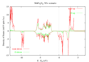
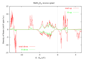
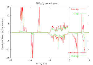
Regarding the density of states (DOS) of MnFe2O4 in the calculated ground state normal spinel structure (the top panel of Fig. 1), one can see that it is insulating, with a gap of about 0.075 eV which is slightly larger than the experimental value obtained from transport measurements. A larger gap of about 0.3 eV is seen for the inverse spinel structure (bottom panel), but the spin splitting of the conduction band is here considerably smaller than for the ground state normal spinel scenario (Table 3). In variance to the normal and inverse spinel cases, the ’N3+’ scenario (middle panel) is found to be half-metallic.
For all the studied scenarios, the valence band is predominantly of the oxygen type, with a very small admixture of the TM character, and its polarization at the top of the band changes from positive to negative between the inverse and normal spinel scenarios (Table 3). What also changes substantially when moving from the normal to inverse spinel scenario is the conduction band splitting, which for the normal spinel scenario is about 2.5 eV larger than that of the inverse spinel case. The reason being that the unoccupied TM -states are substantially pushed up in energy when in the normal spinel environment. Considering that in reality MnFe2O4 is not a pure normal spinel compound, the exchange splitting of the conduction bands is most likely to be somewhere in between the values calculated for the normal and inverse spinel scenarios. Of course, the larger the splitting, the more advantageous should it be for the spin filtering properties.
| ’I’ scenario | ’N’ scenario | |
|---|---|---|
| VBM↑ - VBM↓ | 0.69 | -0.91 |
| CBM↑ - CBM↓ | 1.31 | 3.85 |
| CBM↑ - VBM↑ | 1.64 | 4.84 |
| CBM↓ - VBM↓ | 1.02 | 0.075 |
| Gap | 0.33 | 0.075 |
To understand details of the densities of states shown in Fig. 1, associated with the localized TM states, one should keep in mind that in the normal spinel scenario (top panel) which, as already mentioned, is the calculated ground state structure for this compound, the tetrahedral sublattice is populated by Mn2+ ions and that in this case five minority Mn electrons are described as localized states, seen just below the predominantly O 2 valence band, at about -6 eV. The unoccupied, majority Mn electrons give rise to the states seen as peaks above the Fermi energy at about +6 eV. The octahedral sublattice is populated by Fe3+ ions, with five majority electrons localized, as the two sublattices are anti-parallel to one another. As a result the localized majority Fe states are seen at about -12 eV below the Fermi energy. The unoccupied Fe states, the minority ones, are seen just above the Fermi energy, over the range of up to about 3.5 eV.
In the ’N3+’ scenario (middle panel), one minority Mn electron gets delocalized to realize Mn3+ ions on the tetrahedral sites. As a result the localized, minority Mn peak has moved down in energy, lying just above -10 eV, while the fifth, now delocalized, minority electron appears at the Fermi energy, bringing down also the unoccupied, minority, Fe states. The situation changes in the inverse spinel scenario (bottom panel), as now Mn2+ ions reside on B1 sites of the octahedral sublattice, while the Fe3+ ions populate the tetrahedral sublattice and B2 sites of the octahedral sublattice. Thus on the tetrahedral sites we have five minority Fe electrons which give rise to the peak at about -12 eV, while the localized Fe electrons of the octahedral sublattice are seen as the peak on the majority side, at about -14 eV. The five localized Mn majority states are again seen just below the valence band at about -7 eV. The unoccupied Mn minority bands are seen at about 6 eV above the Fermi energy. The five unoccupied, majority, Fe states, associated with the tetrahedral sublattice, are seen at about 2.5 eV above the Fermi energy. Finally, the unoccupied, minority, Fe states of the octahedral sublattice are seen as two separate peaks above the Fermi energy. Note, however, that the SIC-LSD eigenvalues have no direct physical interpretations as removal energies, and thus should not be directly compared with spectroscopies. To do so, one would need to take into account relaxation/screening effects that are not included in such an effective one-electron theory as SIC-LSD. One way to accomplish this is to employ the calculations,DelSCF ; WalterPr ; photoemission_comment and another is the SIC-LSD based optimized effective potential (OEP) method.Sharp ; Talman ; OEP ; photoemission_comment
| Scenario | MnFe2O4 | Fe3O4 | CoFe2O4 | NiFe2O4 |
|---|---|---|---|---|
| I | 5.00 | 4.00 | 3.00 | 2.00 |
| I3+ | 4.10 | 4.00 | 3.00 | 2.00 |
| N | 5.00 | 6.00 | 7.00 | 8.00 |
| N3+ | 5.00 | 4.00 | 5.60 | 6.80 |
The magnetic properties change when moving from the normal to inverse spinel scenario, as seen in Table 4, where we compare the total spin magnetic moments for all the studied spinel ferrites. The total spin magnetic moment for MnFe2O4 is 5 per formula unit, for both insulating and half-metallic solutions, while for the metallic ’I3+’ scenario the spin moment is reduced to 4.1 per formula unit. Note that unlike in the other ferrites there is no change in the total spin magnetic moment between the normal and inverse spinel scenarios. The reason being that, as seen in Table 5, there are only very small changes in the values of the spin moments of the transition metal ions, that are compensated by changes in the induced oxygen spin moments.
| Scenario | FeA3+ | MnB12+ | FeB23+ | O1 | O2 |
| I | -4.09 | 4.58 | 4.11 | 0.12 | 0.03 |
| Scenario | MnA2+ | FeB13+ | FeB23+ | O1 | O2 |
| N | -4.49 | 4.11 | 4.11 | 0.34 | 0.34 |
Including spin-orbit coupling for the ground state normal spinel scenario for MnFe2O4 compound, we find no considerable orbital moments either on Mn (-0.0005 ) or on Fe ions (0.019 ). As a result, the total orbital moment is of the order of 0.045 per formula unit, while at the same time the total spin moment is changed from 5.0 to 4.9995 per formula unit. Also, even with SOC included, we still observe a small energy gap of 0.064 eV, which incidently is in good agreement with the transport experiments. flores
IV.2 Fe3O4
Based upon its high magnetoresistive properties, magnetite is of interest for technological applications, as e.g. computer memory, magnetic recording, etc. Magnetite is thought to be half-metallic, with the highest known Tc of 860 K. At about TV=122 K it undergoes a transition to an insulating state, associated with some kind of charge order, setting in on the octahedral sites, and a distortion of the crystal structure from the inverse spinel cubic to monoclinic Verwey ; Walz ; Wright . Verwey argued that below the transition temperature, TV, the Fe3+ and Fe2+ cations order in the alternate (001) planes, and interpreted this transition as an electron localization-delocalization transition Verwey .
In the earlier paper, we have studied three different types of charge order on the octahedral sites, both in the high temperature (cubic) and low temperature (monoclinic) phases Szotek1 . In this paper, for the sake of comparison with other spinel TM oxides, we concentrate exclusively on the high temperature cubic phase and the scenarios enumerated in Table 4.
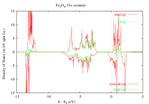
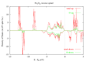
As seen from Table 2 and Fig. 2 (middle panel), the ground state of magnetite in the cubic phase is half-metallic, with all Fe ions in 3+ configuration (five electrons localized). This ground state scenario (’I3+’’N3+’) is the result of a delocalization of the sixth electron of the original Fe2+ ions, that together with Fe3+ ions randomly populate the octahedral B1 and B2 sites in the high-temperature cubic phase. In the ground state scenario, this sixth electron is seen to give rise to the peak at the Fermi energy in the minority channel, together with the other 10 unoccupied minority states associated with the octahedral sites. The five localized tetrahedral FeA minority states appear around -13 eV, while the unoccupied majority FeA states are seen just above the Fermi energy. All the localized majority states of the octahedral sites are at about -12.5 eV. The valence band is of predominantly O character.
The inverse spinel solution (Table 2 and the bottom panel of Fig. 2), corresponding to the assumed Verwey charge order, lies about 1.5 eV above the ground state. In this scenario, the above mentioned sixth electron is localized on the B1-octahedral sites, and appears as a small hump at the bottom of the minority valence band. The remaining five states of the FeB1 sites are seen at about -8 eV below the Fermi energy in the majority bands. The five localized majority FeB2 states lie at about -12.5 eV. The minority FeA states (seen below -10 eV) are localized, and the majority FeA states are unoccupied, occuring at about 3 eV above the Fermi energy. As a result, since the four remaining minority FeB1 states and five minority FeB2 states are also unoccupied, our calculations for this scenario give an insulating state with a gap of 0.7 eV. Understandably, as the latter has been calculated for the high-temperature inverse spinel structure, its value is much larger than the experimental value of 0.14 eV gap , measured for the true, low temperature monoclinic phase.gap1
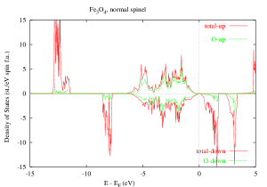
Our calculations for the normal spinel structure give the most energetically unfavourable solution for magnetite, lying about 2.5 eV above the ’I3+’ ground state scenario. In this normal spinel case (top panel of Fig. 2), we obtain an insulating solution with an energy gap of 0.08 eV. Here, the tetrahedral sites are occupied by Fe2+ ions, while the octahedral sites are populated with Fe3+ ions. As a result, five localized minority FeA states lie at about -8 eV, while the sixth localized, majority, FeA state sits right at the bottom of the majority valence band. All the remaining unoccupied majority FeA states are just about seen at 5 eV above the Fermi energy, giving rise to a large exchange splitting of the conduction band. The localized, majority, FeB1 and FeB2 states are seen at -12.5 eV, while their unoccupied, minority, states lie just above the Fermi energy, over the range of about 3-4 eV. So, again like in MnFe2O4, we see a large change in the exchange splitting of the conduction band when moving from the inverse to normal spinel structure. For the inverse spinel scenario (’I’) it is of the order of 1.6 eV, while for the normal spinel arrangement it increases to 3.65 eV (Table 6). It is interesting to note, that in the normal spinel structure the sixth localized electron of the Fe2+ ion occupies one of the eg orbitals, while in the inverse spinel scenario it populates one of the t2g states.
| ’I’ scenario | ’N’ scenario | |
|---|---|---|
| VBM↑ - VBM↓ | 0.06 | -0.35 |
| CBM↑ - CBM↓ | 1.61 | 3.65 |
| CBM↑ - VBM↑ | 2.33 | 4.08 |
| CBM↓ - VBM↓ | 0.78 | 0.08 |
| Gap | 0.72 | 0.08 |
| Scenario | Mtotal | M | M | M | M | M |
|---|---|---|---|---|---|---|
| I | 4.00 | - | -4.00 | 3.57 | - | 4.08 |
| I3+ | 4.00 | - | -4.02 | - | 3.90 | 3.90 |
| N | 6.00 | -3.46 | - | - | 4.09 | 4.09 |
The total spin magnetic moment per formula unit is 4 (Table 4) for all the scenarios studied, with the exception of the normal spinel scenario, where we see a 50% increase to 6 . As all the scenarios give rise to either insulating or half-metallic states, the spin magnetic moments are naturally integer numbers. Table 7 explains how the 50% increase in the total spin magnetic moment comes about when switching from the inverse to normal spinel structure. In the inverse spinel case the spin moment of the tetrahedral Fe ions gets just about cancelled by the spin moment of the B2-octahedral sites, so that the total spin moment is mostly due to the Fe2+ ions on the B1-sites. In the normal spinel, on the other hand, the spin moment of the tetrahedral Fe2+ ions is smaller, and oppositely alligned with the spin moments of the Fe3+ ions that occupy all the octahedral sites. Bearing in mind that there are twice as many octahedral sites as the tetrahedral ones, the substantial increase is easy to account for, especially that the induced spin moments on the oxygen sites do not differ much between the two scenarios.
Including spin-orbit coupling for the ground state ’I3+’ scenario leads to a very small total orbital moment of about 0.05 per formula unit, while the total spin moment is very slightly reduced from 4 to 3.9998 per formula unit. The orbital moments due to the individual Fe-ions are similarly very small, with the tetrahedral Fe being -0.015 and the octahedral Fe of 0.035 .
IV.3 CoFe2O4
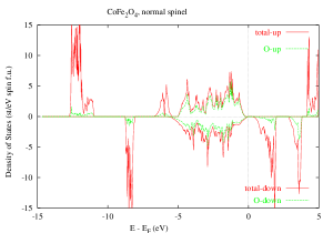
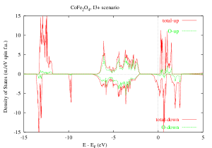
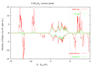
This compound is believed to be mostly of the inverse spinel kind pattrick ; waseda ; neill , with divalent Co ions occupying predominantly the octahedral sites. However, similarly to magnetite in the high temperature cubic phase, our calculations find the ground state of CoFe2O4 to be half-metallic and of the ’I3+’ type (Table 2 and Fig. 3, middle panel). As seen in Table 2, the inverse spinel scenario (’I’) is not far, lying only 0.2 eV higher in energy. What this seems to imply is that this compound prefers the inverse arrangement of atoms, independently of the actual valence of the Co ions. The normal spinel solution is about 1.1 eV away. Although the ground state we find is half-metallic, the inverse spinel scenario (’I’), with Co2+ ions occupying the B1 octahedral positions, describes CoFe2O4 as an insulator, with a gap of 0.8 eV, which is reduced to 0.21 eV in the normal spinel case (Table 8 and Fig. 3).
To understand in detail the densities of states in Fig. 3 note that Co has only one minority electron more than Fe. So, the Co2+ ion has two localized minority electrons, in addition to the five majority ones. In the ground state ’I3+’ scenario (middle panel in Fig. 3), one of these two minority electrons gets delocalized, contributing to the states at the Fermi energy, while the other, localized, one is seen as a sharp peak just above -10 eV. All the remaining main features of DOS for this scenario are exactly like in the case of ’I3+’ scenario in magnetite.
For the inverse spinel structure (bottom panel of Fig. 3), the situation is again very much like in magnetite (bottom panel of Fig. 2), with the exception that now we have a small double hump, at about -7 eV, slightly detached from the predominantly O 2 valence band, while in magnetite it was still attached to the valence band and represented just a single minority electron.
In the normal spinel scenario the Co2+ ions now reside on the tetrahedral sites, with their five localized minority states seen as a rather sharp peak at about -8 eV, in the top panel of Fig. 3. The remaining two localized majority states are sitting just below the majority valence band. All the other features are like in magnetite.
Similarly to other ferrites, one sees substantial change in the exchange splitting of the conduction band between the inverse and normal spinel scenarios, from 1.28 eV to 4.07 eV. Also, the negative spin polarization of the valence band is seen in the normal spinel, while a positive one in the inverse spinel structure. Like in magnetite, for the divalent Co2+ ions on the tetrahedral sites in the normal spinel structure, the eg minority states are populated before the t2g ones, which is in variance to the inverse spinel structure. In the latter case, the Co2+ ions reside on the B1 octahedral sites, and the t2g states are lying lower in energy than the eg states.
| ’I’ scenario | ’N’ scenario | |
|---|---|---|
| VBM↑ - VBM↓ | 0.22 | -0.24 |
| CBM↑ - CBM↓ | 1.28 | 4.07 |
| CBM↑ - VBM↑ | 2.08 | 4.52 |
| CBM↓ - VBM↓ | 1.02 | 0.21 |
| Gap | 0.80 | 0.21 |
As seen in Table 4, the total spin magnetic moment for both the ’I’ and ’I3+’ scenarios is 3 per formula unit. It is reduced from 4 in magnetite due to the smaller value of the spin moment of the divalent Co-ion of 2.58 (Table 9), in comparison with the spin moment of the divalent Fe ions of 3.57 (Table 7). What is however more dramatic is the change of the spin moment when moving from the inverse to the normal spinel arrangement of ions. Table 4 shows that in the normal spinel scenario the total spin moment is 7 per formula unit, which again is due to the fact that the octahedral sites are populated exclusively by Fe3+ ions, whose spin moments are arranged in parallel to one another and whose magnitudes are considerably larger than the moment of Co2+ ions on the tetrahedral sites.
| Scenario | FeA3+ | CoB12+ | FeB23+ | O1 | O2 |
| I | -4.11 | 2.58 | 4.11 | 0.13 | 0.07 |
| Scenario | CoA2+ | FeB13+ | FeB23+ | O1 | O2 |
| N | -2.58 | 4.13 | 4.13 | 0.32 | 0.32 |
With respect to spin-orbit coupling we find the total orbital moment of the ground state ’I3+’ scenario to be quite substantial of the order of 0.58 per formula unit, and associated mostly with the Co3+ ion. As the total spin moment is reduced from 3 to 2.9997 per formula unit, the ratio of the total orbital to spin moment is 0.19. The ratio of the orbital to spin moment for the Co3+ ion itself is 0.21.
IV.4 NiFe2O4
NiFe2O4 is a ferromagnetic insulator that is of possible interest as a spin filter in MTJs ulrike ; agnes . This compound has the Curie temperature of 850 K, and hence has a great potential for technological applications.
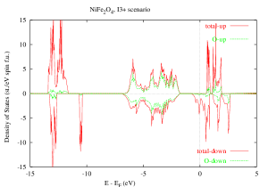
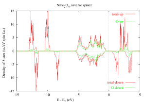
In agreement with experiments, we find the ground state of NiFe2O4 to be insulating and of the inverse spinel kind (Table 4 and the bottom panel of Fig. 4). The calculated energy gap is 0.98 eV (Table 10). It gets reduced to 0.26 eV in the normal spinel scenario, which is the most energetically unfavourable solution for this compound. In the ground state ’I’ scenario, the octahedral B1-sites are occupied by Ni2+ and B2 sites by Fe3+ ions, while the tetrahedral sites are populated exclusively by Fe3+ ions. Replacing the Co2+ ions on the octahedral sites in CoFe2O4 by Ni2+ leads to the reduction of the total spin magnetic moment of 3 in CoFe2O4 to 2 in NiFe2O4 (Table 4), since the spin magnetic moment of the Ni2+ ion is 1.57 (Table 11), as compared to 2.58 spin moment of the Co2+ ion (Table 9). The oxygen spin moments in both materials are comparable, and aligned in parallel to the cation spin moments on the octahedral sites. The width of the predominantly oxygen 2 valence band in NiFe2O4 is comparable to the one of CoFe2O4, but is reduced with respect to the valence band of magnetite. The reason being that the sixth localized electron of the Fe2+ ion (in Fig. 2 (middle panel) seen at the bottom of the valence band between -5.0 and -6.0 eV) is strongly hybridized with the oxygen band. The situation is different in NiFe2O4, where the three localized minority t2g electrons, seen at about -8.0 eV (Fig. 4, bottom panel), are well separated from the bottom of the valence band. Also, the exchange splitting of the conduction band, of importance to spin filtering, is about 20% smaller in NiFe2O4 than in the Verwey phase of Fe3O4.
| ’I’ scenario | ’N’ scenario | |
|---|---|---|
| VBM↑ - VBM↓ | 0.10 | -0.12 |
| CBM↑ - CBM↓ | 1.21 | 2.93 |
| CBM↑ - VBM↑ | 2.19 | 3.31 |
| CBM↓ - VBM↓ | 1.08 | 0.26 |
| Gap | 0.98 | 0.26 |
| Scenario | FeA3+ | NiB12+ | FeB23+ | O1 | O2 |
| I | -4.11 | 1.57 | 4.11 | 0.14 | 0.07 |
| Scenario | NiA2+ | FeB13+ | FeB23+ | O1 | O2 |
| N | -1.65 | 4.13 | 4.13 | 0.35 | 0.35 |
To understand details of the DOS of the ’I3+’ scenario of NiFe2O4, it is helpful to follow the discussion of the same scenario for CoFe2O4, keeping in mind that a Ni3+ ion has two minority electrons in addition to the five majority ones, localized by SIC. Obviously, as already mentioned when discussing MnFe2O4, the positions of the localized peaks calculated in the SIC-LSD should not be directly compared with photoemission experiments.photoemission_comment
The changes in the electronic structure of NiFe2O4 when moving from the ground state inverse spinel structure to the normal spinel scenario are immediately obvious from comparing the bottom and top panels of Fig. 4. In the normal spinel case the Ni2+ ions occupy the tetrahedral sites, while the octahedral sites are solely taken by the Fe3+ ions. As a result, the total spin magnetic moment is increased from 2 per formula unit to 8 per formula unit, as seen in Table 2, in agreement with experimental findings of Refs. ulu, ; Manuel, . However, as seen in the top panel of Fig. 4, the density of states is still just insulating in both spin channels. Also, unlike in the case of the inverse spinel structure, the valence band is strongly spin-polarized, and the polarization is negative. The oxygen spin magnetic moment is 0.35 , aligned in parallel to the Fe spin moment (see Table 11), and three times the value it has in the inverse spinel structure. Also, the Ni spin moment is slightly increased in magnitude to -1.65 . Moreover, the exchange splitting of the conduction band is more than twice increased in the normal spinel, in comparison with the inverse spinel structure, from 1.21 eV to 2.93 eV. As in the case of the other spinel ferrites in realizing Ni2+ ions, the eg states are populated first, i. e., are lying lower in energy than the t2g states, which is opposite to the inverse spinel structure. However, energetically, the normal spinel structure for NiFe2O4 is very unfavourable with respect to the inverse spinel structure (Table 2).
Including the spin-orbit coupling for the ground state inverse spinel scenario gives
rise to the total orbital moment of 0.67 per formula unit, and is mostly
due to Ni ions, with some minor contributions from Fe atoms. This calculated value is
over two times larger than calculated from LSD in Ref. guo2, .
Also, in the earlier SIC-LSD calculations for TM oxides Svane and Gunnarsson ASOG
obtained the orbital moment for NiO of 0.27 , which is substantially smaller
than in the present calculations. Since the total spin moment is slightly reduced to
1.9997 per formula unit, when SOC is taken into account, hence the ratio of
the total orbital and spin moments is calculated to be about 0.34.
The latter is in good agreement with the experimental
estimates of 0.270.07 gerrit and 0.34 (within error bars of up to
0.11) for Ni in NiFe2O4 and NiO. fernandez ; gerrit
Note that the orbital moment due to the Ni2+ ion alone is about 0.7 , while
its spin moment is 1.58 , both per formula unit, giving rise to the orbital to
spin moment ratio of 0.44 for this ion. The total orbital moment is mostly due to the
Ni2+ ion, as the contributions of other TM ions are smaller by an order of magnitude
or so.
V Conclusions
We have shown that, owing to a better treatment of correlations, SIC-LSD can provide useful insights to the nature of a number of spinel ferromagnetic insulators. We have been able to address the issues of the normal versus inverse spinel arrangements in these systems, their electronic and magnetic properties and the valence of the transition metal atoms. We find all the studied ferrites to be insulating for both the inverse and normal spinel scenarios, with the calculated energy gaps being smaller in the normal spinel environment, however showing an increasing trend when moving from MnFe2O4 to NiFe2O4. We have observed dramatic increase of the calculated spin magnetic moments, as well as the exchange splitting of the conduction bands, when moving from the inverse to normal spinel scenarios, some of which have been observed in experiments. Manuel
The total energy considerations seem to favour the inverse spinel arrangement of TM ions as the ground state configurations for all the studied ferrites, with the possible exception of MnFe2O4 where the normal spinel environment may be preferred, with Mn2+ ions on the tetrahedral sites and the Fe3+ ions on the octahedral sublattice. Also, based on the total energy arguments, we find a partial delocalization of the minority spin states to be favourable in Fe3O4 and CoFe2O4, leading to the half-metallic ground states with all TM ions in the trivalent configuration and in the inverse spinel arrangement. The fully inverse spinel scenario, with the Fe3+ ions on the tetrahedral sites and the octahedral sites occupied both by Ni2+ ions and Fe3+ ions, is found to be the ground state only in NiFe2O4. Finally, these findings constitute a good starting point for further studies, incorporating alloying of the normal and inverse spinel structures.
Acknowledgements
LP was supported by the Division of Materials Science an Engineering, Office of Basic Energy Sciences, US Department of Energy.
References
- (1) I. Zutic, J. Fabian and S. Das Sarma, Rev. Mod. Phys. 76, 323 (2004).
- (2) J.M.D. Coey and M. Venkatesan, J. Appl. Phys. 91, 8345 (2002).
- (3) S. S. P. Parkin, C. Kaiser, A. Panchula, P. M. Rice, B . Hughes, M. Samant, and S.-H. Yang, Nat. Mater. 3, 862 (2004).
- (4) S. Yuasa, T. Nagahama, A. Fukushima, Y. Suzuki, and K. Ando, Nat. Mater. 3, 868 (2004).
- (5) J. S. Moodera, X. Hao, G. A. Gibson, and R. Meservey, Phys. Rev. Lett. 61, 637 (1988).
- (6) P. LeClair, J.K. Ha, H.J.M. Swagten, C.H. van de Vin, J.T. Kohlhepp, and W.J.M. de Jonge, Appl. Phys. Lett. 80, 625 (2002).
- (7) V. A. M. Brabers, Handbook of Magnetic Materials, vol. 8 (1995).
- (8) M. Pénicaud, B. Siberchicot, C. B. Sommers, J. Kübler, JMMM 103 212 (1992).
- (9) U. Lüders, M. Bibes, K. Bouzehouane, E. Jacquet, J.-P. Contour, S. Fusil, J.-F. Bobo, J. Fontcuberta, A. Barthélémy, and A. Fert, Appl. Phys. Lett. 88, 082505 (2006).
- (10) U. Lüders, A. Barthélémy, M. Bibes, K. Bouzehouane, S. Fusil, E. Jacquet, J.-P. Contour, J.-F. Bobo, J. Fontcuberta, and A. Fert, Adv. Mater. (in press); cond-mat/0508764.
- (11) U. Lüders, M. Bibes, J.-F. Bobo, M. Cantoni, R. Bertacco, and J. Fontcuberta, Phys. Rev. B 71, 134419 (2005).
- (12) U. Lüders, G. Herranz, M. Bibes, K. Bouzehouane, E. Jacquet, J.-P. Contour, S. Fusil, J.-F. Bobo, J. Fontcuberta, A. Barthélémy, and A. Fert, J. Appl. Phys. 99, 08K301 (2006).
- (13) E.J.W. Verwey and P.W. Haayman, Physica (Utrecht) 8 (1941) 979; E.J.W. Verwey, P.W. Haayman and F.C. Romeijan, J. Chem. Phys. 15 181 (1947).
- (14) J.P. Wright, J.P. Attfield, and P.G. Radaelli, Phys. Rev. Lett. 87, 266401 (2001).
- (15) V. I. Anisimov, I. S. Elfimov, N. Hamada, and K. Terakura, Phys. Rev. B 54, 4387 (1996).
- (16) V. N. Antonov, B. N. Harmon, V. P. Antropov, A. Ya. Perlov, and A. N. Yaresko, Phys. Rev. B 64, 134410 (2001).
- (17) I. Leonov, A. N. Yaresko, V. N. Antonov, M. A. Korotin, and V. I. Anisimov, Phys. Rev. Lett. 93, 146404 (2004).
- (18) H.-T. Jeng, G. Y. Guo, and D. J. Huang, Phys. Rev. Lett. 93, 156403 (2004).
- (19) G. K. H. Madsen and P. Novak, Europhys. Lett. 69, 777 (2005).
- (20) Z. Szotek, W.M. Temmerman, A. Svane, L. Petit, G.M. Stocks and H. Winter, Phys. Rev. B 68, 054415 (2003).
- (21) H-T Jeng and G. Y. Guo, JMMM 239, 88 (2002).
- (22) H-T Jeng and G. Y. Guo, JMMM 240, 436 (2002).
- (23) D. J. Singh, M. Gupta, and R. Gupta, Phys. Rev. B 65, 064432 (2002).
- (24) X. Zuo and C. Vittoria, Phys. Rev. B 66, 184420 (2002).
- (25) W.M. Temmerman, A. Svane, Z. Szotek, and H. Winter, in ”Electronic Density Functional Theory: Recent Progress and New Directions”, Eds. J.F. Dobson, G. Vignale, and M.P. Das (Plenum Press, New York and London, 1998).
- (26) A. Svane and O. Gunnarsson, Phys. Rev. Lett. 65, 1148 (1990).
- (27) Z. Szotek, W.M. Temmerman, and H. Winter, Phys. Rev. B 47, 4029 (1993).
- (28) P. Strange, A. Svane, W.M. Temmerman, Z. Szotek and H. Winter, Nature 399, 756 (1999).
- (29) J.P. Perdew and A. Zunger, Phys. Rev. B23, 5048 (1981).
- (30) O.K. Andersen, Phys. Rev. B12, 3060 (1975).
- (31) O.K. Andersen and O. Jepsen, Phys. Rev. Lett. 53, 2571 (1984).
- (32) H.L. Skriver, The LMTO Method, Springer Series in Solid-State Sciences 41, Springer Verlag, 1984.
- (33) J. M. Hastings and L. M. Corliss, Phys. Rev. 104, 328 (1956).
- (34) G. A. Sawatzky, F. van der Woude, and A. H. Morrish, Phys. Rev. 187, 747 (1969).
- (35) L. Braicovich, A. Tagliaferri, G. van der Laan, G. Ghiringhelli, and N. B. Brookes, Phys. Rev. Lett. 90, 117401 (2003).
- (36) W.R.L. Lambrecht and O.K. Andersen, Phys. Rev. B 34, 2439 (1986).
- (37) A. G. Flores, V. Raposo, L. Torres, and J. Iniguez, Phys. Rev. B 59, 9447 (1999).
- (38) A. J. Freeman, B. I. Min, and M. R. Norman, Handbook on the Physics and Chemistry of Rare Earths, eds. K. A. Gschneidner Jr., L. Eyring and S. Hüfner (North Holland, Amsterdam, Oxford, New York, Tokyo), 1987, Vol. 10, pp. 165-229.
- (39) W. M. Temmerman, Z. Szotek, and H. Winter, Phys. Rev. B 47, 1184 (1993).
-
(40)
To improve the agreement between the calculated position of the
TM states from the SIC-LSD method and the photoemission measurement, one can perform
calculations, that is calculations of the total energy difference between two
configurations of TM assumed to represent well the initial and final states of a photoemission
experiment. This is expressed by the formula
,
meaning that one removes an electron from a TM level and introduces it at the top of the valence
band, thus increasing the total number of valence electrons, , by 1. Here represents the
total energies of the respective and configurations.
Of course, a problem one faces with this kind of estimate is that the correct final state
might not be the ground state of the system with one electron removed.
Another way of improving the agreement with spectroscopies is to apply the OEP philosophy. The SIC-LSD method is an orbital dependent density functional theory. Formally, however, SIC-LSD may be viewed as a standard density functional theory, implying that the SIC-LSD energy functional can be represented as a functional of the total charge density alone and minimized with respect to it. This means that there exists an effective Kohn-Sham equation with an effective potential, which is common to all Kohn-Sham states, is self-interaction free and depends only on the total charge density. Here the situation is completely analogous to the optimized effective potential introduced in connection with the Hatre-Fock approximation,iafrate ; kotani for which case the Kohn-Sham eigenvalues are often compared to quasiparticle energies, with a considerable improvement over the Hartree-Fock eigenenergies. Adopting the OEP philosophy, one can search for the effective potential, which reproduces the SIC spin-density, and with such a potential derive the density of the localized TM states. The search may be constrained by looking only for that particular potential shift on the TM sites, which will reproduce the self-consistent TM spin moment of the SIC-LSD calculations. - (41) J. B. Krieger, Y. Li, and G. J. Iafrate, Phys. Rev. A 45, 101 (1992); J. B. Krieger, Y. Li, and G. J. Iafrate, Phys. Rev. A 46, 5453 (1992); Y. Li, J. B. Krieger, and G. J. Iafrate, Phys. Rev. A 47, 165 (1993).
- (42) T. Kotani, J. Phys.: Condens. Matter 10, 9241 (1998).
- (43) R. T. Sharp and G. K. Horton, Phys. Rev. 90, 317 (1953).
- (44) J. D. Talman and W. F. Shadwick, Phys. Rev. A 14, 36 (1976).
- (45) M. R. Norman and D. D. Koelling, Phys. Rev. B 30, 5530 (1984).
- (46) F. Walz, J. Phys.: Condens. Matter 14 (2002) R285.
- (47) S.K. Park, T. Ishikawa, and Y. Tokura, Phys. Rev. B 58, 3717 (1998).
- (48) Note that our SIC-LSD calculations for the Verwey scenario and the true low temperature monoclinic phase obtained a gap of 0.1 eV,Szotek1 which compares well with the experimental value of 0.14 eV gap .
- (49) R. A. D. Pattrick, G. van der Laan, C. M. B. Henderson, P. Kuiper, E. Dudzik, and D. J. Vaughan, Eur. J. Mineral. 14, 1095 (2002).
- (50) Y. Waseda, K. Shinoda, and K. Sugiyama, Z. Naturforsch. 50a, 1199 (1995).
- (51) H. St.-C. O’Neill and A. Navrotsky, Am. Mineral. 68, 181 (1983).
- (52) G. van der Laan, C. M. B. Henderson, R. A. D. Pattrick, S. S. Dhesi, P. F. Schofield, E. Dudzik, and D. J. Vaughan, Phys. Rev. B 59, 4314 (1999).
- (53) V. Fernandez, C. Vettier, F. de Bergevin, C. Giles, and W. Neubeck, Phys. Rev. B 57, 7870 (1998).