Pseudospin vortex-antivortex states with interwoven spin textures in double layer quantum Hall systems
Abstract
Recent experiments on strongly correlated bilayer quantum Hall systems strongly suggest that, contrary to the usual assumption, the electron spin degree of freedom is not completely frozen either in the quantum Hall or in the compressibles states that occur at filling factor These experiments imply that the quasiparticles at could have both spin and pseudospin textures i.e. they could be CP3 skyrmions. Using a microscopic unrestricted Hartree-Fock approximation, we compute the energy of several crystal states with spin, pseudospin and mixed spin-pseudospin textures around as a function of interlayer separation for different values of tunneling () , Zeeman (), and bias () energies. We show that in some range of these parameters, crystal states involving a certain amount of spin depolarization have lower energy than the fully spin polarized crystals. We study this depolarization dependence on and and discuss how it can lead to the fast NMR relaxation rate observed experimentally.
pacs:
73.21.-b,73.40.-c, 73.20.QtI Introduction
It is now well established that the two-dimensional electron gas (2DEG) in a double-quantum-well system (DQWS) at filling factor has a broken symmetry ground state that can be described as either an easy-plane pseudospin ferromagnet or as an excitonic superfluid. The ferromagnetic state (in the pseudospin language) has finite interlayer coherence even in the absence of tunneling if the interlayer separation is lower than a critical layer separation where is the magnetic length. This is an incompressible state supporting a quantum Hall effect (QHE). The phase diagram and physical properties of this state have been extensively studied over the past fifteen years (for a review, see Refs. dassarmalivre, ,ezawalivre, ).
In most studies of the bilayer coherent states at or near filling factor , it is generally assumed that, due to the strong magnetic field, the ground state is fully spin polarized. The spin degrees of freedom could thus be left out of the analysis. Recent experiments, however, cast some doubt on the validity of this assumption. These experiments include the measurementsawadacp3 of the dependence of the activation energy of the bilayer quantum Hall state at on an in-plane field, and the measurementspielmanprl ; kumadaprl of the nuclear magnetic relaxation (NMR) time near .
The monolayer quantum Hall state at is a spin ferromagnet. In the absence of Zeeman coupling, the lowest-energy charged excitation is a spin-textured topological object called a Skyrmionsondhi ; barret ; schmeller . Measurement of the activation energy shows an increase of the energy gap when the magnetic field is tilted away from the axis at . This is easily understood since keeping the filling factor constant means increasing the magnetic field, so the increase in activation energy reflects the increase in the Zeeman energy cost of the skyrmions. By contrast, measurementmurphy of the activation energy in the bilayer quantum Hall state at shows a strong decrease of this energy with tilting until some critical angle above which the activation energy ceases to depend on This anomalous behaviour of the activation energy was interpreted as a change in the ground state of the system at due to a the occurence of a commensurate-incommensurate transition.kunyangci The lowest-energy charged excitation of the spin-polarized bilayer system at is a bimeron, i.e. a skyrmion in the pseudospin field. A Hartree-Fock calculation of the behavior of the bimeron energy in tilted magnetic field reproduces qualitatively the features found in the experiment.breycristalbimerons
Sawada et al.sawadacp3 measured the activation energy of the 2DEG in a DQWS as a function of a parallel magnetic field and electrical bias between the layers. They define the imbalance parameter where is the density in the right(left) layer of the DQWS. At , the activation energy showed the behavior expected for pseudospin-skyrmions (i.e., bimerons) while at , where all electrons reside in one well, the behavior was that expected for a spin-skyrmion. Sawada et al. found a continuous evolution from pseudospin-skyrmion to spin-skyrmion as the imbalance parameter was increased in various samples with tunneling energies ranging from K to K. They concluded that the excited quasiparticles must contain both spin and pseudospin flips in order to explain their results. In particular, the behavior of the activation energy could not be explained by a level crossing between skyrmion and a bimeron excitations. Instead, the bimeron excitation, at the balance point, continuously transformed into a spin-skyrmion at high bias. This suggests the quasiparticles at these biases may be some object that interpolates between the two types of skyrmions. Such objects have been studied in the field theoretic literature by Ghosh and Rajaramanrajaramancp3 , and more recently by Ezawa and Tsitsishviliezawasu4 , who dubbed these objects CP3 skyrmions. In this last work, good agreement between theoretical calculations and the measurements of Sawada et al. were obtained.
Another set of experiments confirming the necessity to take into account spin depolarization in the ground state of the 2DEG around are those of Spielman et al.spielmanprl and by Kumada et al.kumadaprl . In these experiments, the NMR relaxation time is measured as a function of filling factor. (In Ref. kumadaprl, , this is also done as a function of an electrical bias.) The behavior of seen in these experiments is reminescent of that measuredtyckonmr in monolayer quantum Hall systems where the relaxation rate increases when deviates from . A possible explanation cotegirvinprl involves the inclusion of skyrmions in the groundstate when the system is doped away from . A single skyrmion has it spin aligned with the Zeeman field at infinity, reversed at at the center of the skyrmions, and has nonzero spin components at intermediate distances in a vortex-like configuration. For , the finite density of these objects is expected to condense into a crystal breyprl . The quantum mean-field energy of this crystal is independent of the angle which defines the global orientation of the spin components. Côté et al.cotegirvinprl showed that this extra degree of freedom leads to broken symmetry and hence to a spin wave mode that remains gapless in the presence of the Zeeman field. It is the existence of this extra gapless spin mode in the crystal phase (and possibly in some overdamped form in a Skyrme liquid state) that is believed to be responsible for the rapid nuclear spin relaxation observed in the experiments.
Our goal in this paper is to show that crystal states with some amount of spin depolarization due either to spin-skyrmions or CP3 skyrmions exist around , with lower energy than crystal states with maximal spin polarization. We show this by comparing the energy of several crystal states in the Hartree-Fock approximation. We study the spin and pseudospin textures of these states as the interlayer separation, the Zeeman, tunnel coupling or the electrical bias are varied. Because CP3 crystals must have a gapless spin wave mode, just as the Skyrme crystal in a monolayer QH system has, this crystal state could be responsible for the fast NMR relaxation rate seen in the experiments of Spielman et al.spielmanprl and Kumada et al.kumadaprl . In addition, these Hartree-Fock calculations provide a check on the field theoretic calculations that have been used on the CP3 staterajaramancp3 ; ezawasu4 . In the latter it is assumed that the many body wavefunction can be represented by a local 4-spinor with constant magnitude. While Hartree-Fock introduces its own approximations by using a different approach we may hope to better understand the true many body state.
Our paper is organized as follow. The model hamiltonian and the Hartree-Fock formalism needed to compute the CP3 Skyrme crystal are introduced in Sec. II. In Sec. III, we introduce the CP3 skyrmion and discuss its limiting forms: spin-skyrmion and pseudospin-skyrmion. Our numerical results are presented in Sec. IV. We discuss the relevance of our results to the experiments of Spielman et al.spielmanprl and Kumada et al.kumadaprl in Sec. V.
II Model hamiltonian and Hartree-Fock formalism
II.1 Hamiltonian of the 2DEG
We consider a symmetric double-quantum-well system in a magnetic field and submitted to an electrical bias where are the subband energies in each layer (right and left) in the absence of magnetic field and tunneling. For the sake of limiting the number of parameters characterizing our DQWS, we make a narrow well approximation, i.e. we assume that the width of the wells is small () and treat interlayer hopping in a tight-binding approximation. The single-particle problem is then characterized by the separation (from center to center) between the wells and the tunneling integral . In the Landau gauge where the potential vector is taken as , the Hamiltonian of the non-interacting 2DEG is given by
In Eq. (II.1), is an operator that creates an electron with guiding center in well with spin index We work in the strong quantum limit where we assume that Landau level mixing is negligible and only the Landau level needs to be considered. The energies are defined by and where is the Zeeman energy, is the effective gyromagnetic factor and is the Bohr magneton.
We describe the various phases of the electrons in the DQWS by the set of average values where is an operator that we definecotemethode by
where the Landau level degeneracy is (with the area of the 2DEG). We explain the physical meaning of these operators below.
In the Hartree-Fock approximation, the Hamiltonian of the interacting 2DEG in the DQWS is given by
where the renormalized single-particle energies are defined by
| (2) |
In Eq. (2), and where is the filling factor for state and is the total filling factor of the 2DEG. The Hartree and Fock intrawell and interwell interactions are defined by
II.2 Calculation of the order parameters of the crystal phases
To simplify our notation, we now define the four states and write the order parameters as . From now on, the indices will run from to . The average values are obtained by computing the single-particle Green’s function
whose Fourier transform we define as
so that . In a homogeneous phase, only are nonzero while, in a crystal, only if where is the set of reciprocal lattice vectors of the crystal.
In our numerical calculation, we consider a finite number of reciprocal latttice vectors . Defining the column vectors
where is a Matsubara frequency, and the vectors
along with the matrices
and
we find that the Hartree-Fock equation of motion for the single-particle Green’s function matrix can be written in a matrix form as
| (3) |
where is the hermitian matrix
with
and
| (4) |
In the definition of , the symbols and stand for and the quantity for
The are found by solving numerically the self-consistent equation of motion given by Eq. (3). This equation has many solutions representing the local minima of the Hartree-Fock energy given by
There is no guarantee that a solution is an absolute minimum of . Instead, we compare a finite number of likely solutions and choose the one that minimizes the energy. The numerical scheme to solve Eq.(3) is described in more detail in Ref. cotemethode, .
II.3 Spin and pseudospin fields in the crystal phases
In the Landau gauge and with the Hilbert space restricted to the first Landau level only, an electronic state in a single quantum well system (SQWS) is specified by the two-component spinor where
Similarly, an electronic state in a spin-polarized DQWS can be described by mapping this two-level system into a spin system by using the pseudo-spinor where
For a four-level system (with states as given above), an electronic state is specified by the four-component spinor
The operators that we introduced previously can be mapped into the density operator, , the spin and pseudospin densities operators and (with ) and the 9 operators using the SU(4) algebra (as defined in Ref. ezawasu4, )
| (5) |
| (6) |
| (7) |
| (8) |
where the matrices and are defined by
with a Pauli matrix, and by
where is the unit matrix.
From Eqs. (5)-(8), it is easy to show that the electronic densities in the right and left wells are given by
with the total electronic density given by
The spin densities in the right and left wells are given by
and by
Finally, the pseudospin densities for the up (+) and down (-) spin components are given by
and by
with the total pseudospin density.
Note that by definition Also, and . The four order parameters that are not related to the electron, spin, or pseudospin densities are and their complex conjugates. These densities involve average values of operators that flip both the spin and the pseudospin.
The Hartree-Fock energy per electron can now be written as
| (9) | |||
In Eq. (9), we have defined the interactions
Because of the neutrality of the total system comprising the electrons and the positive donors, we have
In the pseudospin langage, a bias acts as a pseudo-magnetic field that couples to the component of the total pseudospin while the tunneling acts as a pseudo-magnetic field that couples to the component of the total pseudospin. The positive sign in front of the first term on the r.h.s of Eq. (9) is due to our particular choice of mapping ( and ) for the pseudospin states. A positive bias forces the component of the pseudospin down; i.e. pushes the electronic charge in the left well. At zero bias, there is equal population of electrons in both wells and in order to minimize the capacitive energy.
II.4 The coherent liquid state at
At , the 2DEG can have spontaneous interlayer coherence. For nonzero Zeeman coupling, the ground state is well described (but this description is only exact at ) by a state where all electrons are in the symmetric combination of both wells and all spins are polarized. The order parameters are then
irrespective of the value of (for , where is the angle between the pseudospin vector and the axis). In the absence of tunneling, the coherent liquid phase supports a gapless pseudospin wave excitationfertigdispersion that disperses linearly with (for ) at small wavectors and becomes soft at an interlayer separation . This critical separation is increased by a finite tunneling. Above this critical interlayer separation, the interwell coherence is lost. The system is then believed to be formed of two composite fermions liquids with filling factor This state is not captured by the HFA which instead predicts a transition to a charge-density-wave state.
II.5 Influence of a bias
With a bias, the symmetric and antisymmetric states of the non-interacting 2DEG are replaced by the bonding and anti-bonding states defined by
where is the unbalance parameter. At , the ground state has all electrons in the
state (i.e. the symmetric state in this case) with up spin if the Zeeman coupling is non zero.
When interactions are included, we can still easily solve Eq. (3) in the presence of an electric bias, at , assuming that the Zeeman term is non zero so that the 2DEG remains spin polarized. We find
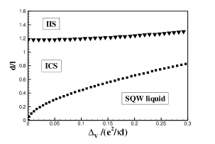
When , the energy of the 2DEG is again invariant with respect to while for , the energy is minimized when . The bias acts as a pseudomagnetic field that forces the pseudospin up or down from the plane. The interlayer coherence is maintained but diminished. In the HFA, there is a critical interlayer separation where interlayer coherence is lost and all the charge is transferred into one well. Notice that the pseudospin mode remains gapless under bias although it now becomes soft at a critical interlayer separation that depends on bias. This situation is represented in Fig. 1 in the case of zero tunneling (essentially the same calculation can be done at nonzero tunneling. As expected, the critical interlayer separation increases with ). For a 2DEG initially in the incoherent state at , it is possible to get a coherent state (and so a quantum Hall effect) by increasing the bias. This transition has been studied in detail both theoreticallybiastheory and experimentallybiasexperiment .
III Topological excitations in the DQWS
III.1 Spin and pseudospin skyrmions
In a monolayer system with only spin degrees of freedom, Eq. (9) becomes
where the interaction
In the absence of Coulomb electrostatic energy and Zeeman coupling and in the gradient approximation where is assumed to vary smoothly over the magnetic length , the energy in Eq. (III.1) can be reduced to that of the O(3) nonlinear sigma model.macdobible The O(3) nonlinear sigma model in a planar geometry possesses topological solitons or skyrmions. Using the complex function which represents the stereographic projection of the unit sphere of spin textures , a skyrmion of Pontryagin index (which corresponds to the addition of one electron to the 2DEG) can be writtenezawalivre as
| (11) |
where Eq. (11) describes a skyrmion of size centered at position in the plane. The spin components are
At infinity, the spins point upward while at the center of the skyrmion, they point downward. The phase in fixes the global orientation of the spins forming the skyrmion.
In quantum Hall systems, skyrmion-antiskyrmion excitations have been shown to have lower energy than the corresponding maximally spin-polarized Hartree-Fock electron-hole excitation if the Zeeman coupling is not too strong.fertigskyrmion ; sondhi Around filling factor , a finite density of skyrmions () or antiskyrmions () are included in the groundstate (with filling fraction ). At K, these quasiparticles condense into a Skyrme crystal.
The equation of motion method derived in Ref. cotemethode, was used some years ago to study the phase diagram of the Skyrme crystal in the space. Numerical resultsbreyprl ; cotegirvinprl show that, in a large portion of the phase space, skyrmions crystallize into a square lattice structure with two skyrmions of opposite phases ( and ) per unit cell. This arrangement was termed (for square lattice antiferromagnetic). More recent calculationscotegroup1 show that, as the Zeeman coupling is increased from small values at fixed quasiparticle filling , the crystal structure changes from a checkerboardbreymeron lattice of merons near (i.e. a skyrmion lattice where each skyrmion splits into two merons of charge with opposite vorticities and where all merons are equally spaced) to a lattice of biskyrmionsnazarov at small a skyrmion lattice at moderate and finally into a lattice of skyrmions (a triangular lattice with three skyrmions with phases per unit cell to avoid the frustration created by the preferred antiferromagnetic ordering of the skyrmionsnazarov ) at higher values of . The spin texture is gradually lost as the Zeeman coupling further increases and we finally have a Wigner crystal of maximally polarized quasiparticles with no spin texture.
For a spin-polarized 2DEG in a DQWS, the energy functional of Eq. (9) becomes
with
In the absence of bias, tunneling and Coulomb electrostatic energies and in the gradient approximation, the energy in Eq. (III.1) can be reduced to that of the anisotropic nonlinear sigma model with a unit pseudospin field .macdobible The topological excitations of this model are bimerons and merons (or pseudospin-skyrmions and pseudospin-merons). A bimeron with topological charge has its pseudospin field given byezawalivre
where are the positions of the two merons forming the bimeron. Alternatively, we can write
where are the positions of the merons in the right and left wells. The angle gives the global orientation of the pseudospin vectors with respect to the axis at infinity. When , we are at the center of the meron on the left(right) well and there the pseudospin .
Bimerons and merons have been studied extensively in the context of the QHE.ezawabimeron ; rajaramanbimeron ; breycristalbimerons Again, bimeron-antibimeron excitations have been shown to be the relevant excitations near Although we have not performed an exhaustive calculation of the phase diagram of bimeron crystals, our numerical resultscotegroup1 show that at finite tunneling, an (or rectangular antiferromagnetic) configuration of bimerons is stable up to an interlayer separation . At very small tunneling, the bimeron lattice becomes a lattice of merons with again the checkerboard configuration. In comparison with Wigner crystal in bilayer systems where a one-component Wigner crystal can only be stabilized at small interlayer distances of order , the interlayer coherence in a bimeron or meron lattice persists to much larger
III.2 CP3 skyrmion
When both spin and pseudospin are active degrees of freedom, electronic states must be described by a four-component spinor. As explained in Ref. rajaramancp3, , this spinor is a CP3 spinor since the DQWS has a U(1) gauge invariance (all four components of the spinor must be transformed by the same phase for the DQWS’s energy to remain invariant). Strictly speaking, a texture of a CP3 spinor can lie wholly in the spin degrees of freedom, or wholly in the pseudospin degrees of freedom. We only have a guarantee that the topological charge associated with the texture integrates to an integer. In this paper we use the phrase “CP3 Skyrmion” to refer to textures in which both the spin and pseudospin degrees of freedom are appreciably varying. This is sometimes referred to as an interwined texture.
To start the iteration process needed to solve Eq. (3), we must provide an approximate solution for the crystal of CP3 skyrmions. From our discussion above, we expect that an configuration of skyrmions could be a likely solution. Following Rajaramanrajaramancp3 , we write the four-component spinor
| (13) |
were and the normalisation factor is
This state contains a skyrmion of size at position in the right well, a skyrmion of size at position in the left well and a bimeron in the spin up component of the pseudospin centered at . The CP3 static energy of this skyrmion is given by
| (14) |
where with a gauge field defined by and a “spin-pseudospin” stiffness. The field must satisfy the constraint . Eq. (14) can be obtained from our Hartree-Fock energy by taking the limit . The solution of Eq. (13) is a skyrmion with topological charge . The CP3 topological charge density is defined by
| (15) |
The order parameters for this single quasiparticle state are given, in real space, by Fourier-transforming this expression, we can easily write the for this state. To write an approximate solution for a crystal of these quasiparticles, we consider the change in the ground state (at ) when a skyrmion is added to the system
where describe the ground state (at ) which has (at zero bias) all electrons in the bonding (or symmetric) state with up spins (see Sec. II). In principle, the fields are zero when we are far away from the position of the skyrmion so that the crystal state can be written approximately as
where is the position vector of the two skyrmions in the unit cell, is a lattice vector, and is the index of the phase of each of the two skyrmions. The order parameters for the crystal state are then given by
| (16) |
In general, it is sufficient to give the given by Eq. (16) on the first or first two shells of reciprocal lattice vectors in order for the program to converge to the CP3 skyrmion crystal. The SLA configuration is obtained by choosing and for the lattice vectors (), and for the positions of the two skyrmions. For the first skyrmion, we take and For the second skyrmion, we take, and in order to rotate the global phase by
IV Numerical results on CP3 crystals
IV.1 Crystal states considered
The HFA does not contain the correlations necessary to describe the ground state at where interwell coherence is lost. For this reason, we limit our numerical calculations of crystal states to interlayer separations In the monolayer and polarized bilayer limits, we found that a square lattice with two skyrmions of opposite phases per unit cell is the ground state in a wide region of parameter space. We thus choose to consider the following states in our analysis:
-
•
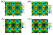
CP3: a square lattice with two spin-pseudospin skyrmions of opposite phases per unit cell as described at the end of Sec. III. This state is represented in Fig. 2 in the case of small tunneling where each skyrmion is broken into two merons of opposite vorticities.
-
•
SPB: a spin-polarized square lattice with two bimerons of opposite phases per unit cell. The spinor of Eq. (13) is replaced by At small tunneling, the bimerons split into a pair of two merons with opposite vorticities. This spin-polarized bimeron (or merons) lattice should be the ground state when the Zeeman energy is of the order or bigger than the tunneling energy.
-
•
SS: this is a symmetric skyrmion state which is a pseudospin-polarized square lattice state with two symmetric-band spin-skyrmions of opposite phases per unit cell. By “symmetric-band”, we mean that the SU(2) spinor for the first electron would be given by in the symmetric-antisymmetric basis ) basis or by in the ) basis. We expect this phase to be the ground state state when tunneling energy dominates the Zeeman energy.
-
•
High Tunneling CP3(HCP3): a square lattice with two spin-pseudospin skyrmion of opposite phase per unit cell. The difference between this state and the CP3 state above is that here the spin texture exists in the symmetric and antisymmetric bands while in the latter it exists separately in each quantum well. This state is the ground state only when the tunneling energy is higher than the Zeeman energy and only for filling factor . We note that the HCP3 state is an intermediate state between SS and SPB states. The textures in the HCP3 state splits into two vortices with charge by reducing the Zeeman gap.
When the tunneling or Zeeman couplings increase, the size of the pseudospin or spin skyrmions decreases. At large values of both these parameters, a limit is reached where the skyrmion state reaches maximal spin and pseudospin polarization. The resulting state may be viewed as a crystal of Hartree-Fock quasiparticles. When interlayer coherence is non zero, the HF quasiparticles are delocalized in both wells and form a coherent Wigner crystal (i.e. a “one-component ”Wigner crystal)
With increasing bias, the CP3 or SS solution will continuously transform into a monolayer spin skyrmion. The SS solution, for example can be written in the basis as in the presence of a bias (where is the unbalance parameter and in the absence of bias).
IV.2 Effect of interlayer separation at zero bias
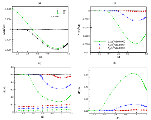
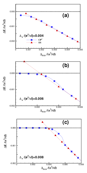
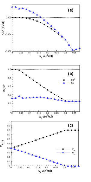
We first compute the energy of the three states just introduced as a function of the interlayer separation for parameters and . Figure 3(a) shows the energy differences and . At small interlayer separation, the ground state is the SPB crystal while above some critical interwell separation that depends on the Zeeman coupling, a CP3 crystal state emerges and remains the ground state up to the largest value of that we consider (i.e. ). Figure 3(b) shows the difference in energy between the CP3 and the SPB crystals for several values of the Zeeman coupling. As expected, the interlayer separation at which the SPB-CP3 transition takes place increases with increasing Zeeman coupling. (We remark that K, so that the difference in energy, at and , is of the order of mK.) Moreover, in Fig. 3(c), we see that the spin polarization per electron varies strongly with interlayer separation in the CP3 crystal state in comparison with the SS state. The spin depolarization of the CP3 state increases with decreasing and reaches a maximum at about . Figure 3(d) shows the behaviour of the pseudospin polarization per electron in the plane i.e. The pseudospin polarization increases when the spin polarization decreases. The value of pseudospin polarization gives some indication of the size of the bimeron in the CP3 skyrmions. When , there are no pseudospin vortices in the phase considered. Note that we have chosen in our analysis a very small value of the tunneling constant. Our results of this section stay essentially the same if the tunneling coupling is exactly zero.
The observation that this CP3 state is most prominent at large suggests that it is stabilized by the interlayer charging energy. The merons of the SPB state involve “tilting” of the pseudospin at their cores into one layer or the other, at an energy cost of order . For large enough , it is energetically favorable to admix spin states so that near their cores the charge of the vortices will be balanced. An examination of the charge densities in each well reveals that the CP3 lattice is indeed more locally balanced than the SPB lattice.
IV.3 Effect of tunneling at zero bias
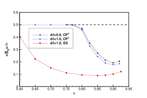
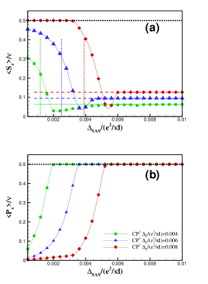
In Fig. 4, we show the behavior of the spin polarization per electron with filling factor for for two values of the interlayer separation. At , . Away from , the spin polarization decreases rapidly for the CP3 crystal until it reaches a minimum at about . Then, as is further decreased and the density of skyrmions increases, the size of the skyrmions also decreases and the Wigner crystal limit is reached where the ground state is again fully spin polarized. The behavior of the spin polarization we find for the CP3 crystal is identical to what was found for Skyrme crystals in a single layer system.breyprl As is increased towards , we also find that the critical interlayer separation for the transition between the SPB and the CP3 states decreases so that the CP3 crystal state is stable over a larger range of interlayer separation for smaller quasiparticle filling. For the SS state that occurs at high tunneling, the variation of the spin polarization is less marked than in the CP3 crystal.
Because the spin polarization is minimal around for we choose this value of the interlayer separation to study the effect of tunneling on the spin polarization. Figure 5 shows the difference in energy and for three values of the Zeeman coupling. At small Zeeman coupling, increasing causes a transition from the CP3 to the SS crystal. At larger Zeeman couplings, where the ground state is the SPB crystal at zero tunneling, increasing causes first a transition to a CP3 crystal (in a very narrow range of ) and then into a SS at larger tunneling values. The CP3 crystal exists only in narrow range of and that range decreases with increasing Zeeman coupling so that the CP3 state disappears at large . Typically, the SS phase occurs for .
The change in the spin and pseudospin polarizations of the CP3 and SS crystals with is shown in Fig. 6 for the values of the Zeeman coupling considered in Fig. 5. We see from this figure that increasing increases the pseudospin polarization and decreases the spin polarization. At the transition from the CP3 to the SS state indicated by the vertical dashed lines in Fig. 6, there is a sharp drop in the spin polarization. This sudden change in and so in the in-plane spin polarization, should lead to abrupt changes in the NMR relaxation time.
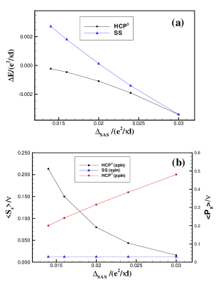
Our results, so far, have been for filling factor . Interestingly, we do not find a precisely analogous spin-pseudospin configuration for filling factors . Instead, as explained in Section IV, we have found an intermediate spin-pseudospin state at large values of and small separations ( ), which we call the HCP3 state. Fig. 7(a) shows the difference in energy of HCP3 or SS and SPB. As we can see in this figure, by increasing the ground state changes from SPB to HCP3 and then to SS. Also in Fig. 7(b) we can see the spin depolarization in HCP3 state as a function of . The spin polarization of the HCP3 state is more sensitive to than the SS state.
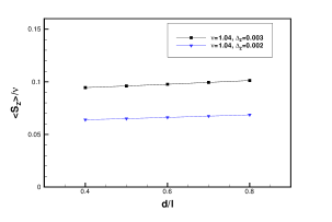
For the SS state also can be the ground state. At we find that the SS state is the ground state for , and The spin polarization with interlayer separation in the SS state is shown in Fig. 8. The linear behaviour is typical of what is obtained for in the SS state (see Fig. 3, for example).
IV.4 Effect of a bias on the spin polarization
To conclude this section, we look at the effect of a potential bias on the spin polarization. Intuitively we understand that a CP3 skyrmion involves a “twist” in some high dimensional space that is difficult to plot in 2D. That twist will occur through degrees of freedom where it costs the least energy, and the texture will vary slowly in sectors where the system is “stiff”. If we can change the stiffness of textures along some direction of phase space we can drive the texture into or out of that degree of freedom. A simple analogy would be to drive an O(3) model into an XY model by making excursions into the z-direction too costly.
The behavior of this system with respect to bias illustrates this physics. We choose the parameters and so that, at the balanced point, the ground state is a spin-polarized meron crystal (SPB). Our numerical results, plotted in Fig. 9, show that there is a transition first into a CP3 crystal and then into the SS state as the applied bias increases. The energy of the CP3 crystal interpolates nicely between the SPB and SS phases as can be seen in the figure. The corresponding spin polarizations are shown in Fig. 9(b). The bias has the effect of inducing a linear spin depolarization of the 2DEG in the CP3 state. In effect, the texture inducing the deviation of charge density from is being shifted from the pseudospin degree of freedom to the spin degree of freedom in a continuous way. Note that the spin polarization varies only slightly with in the SS state. Fig. 9(c) shows the filling factor and in the CP3 state (the exact same curves are obtained in the SS state). Above all the charge is transferred into the right layer and the spin polarization is that appropriate for a monolayer Skyrmion crystal with filling factor and Zeeman coupling and is then independent of the interlayer separation. We expect the marked decrease in the spin polarization with bias to translate into an increase of the NMR relaxation rate with increasing bias.
V Discussion and Conclusion
Our numerical calculations show that crystals involving spin and/or pseudospin textures are likely candidates for the ground state of the 2DEG in a bilayer quantum Hall system around filling factor At small tunneling and for , we find intertwined spin and pseudospin textures (CP3 crystal) with a spin polarization that is strongly interlayer dependent while at higher tunneling, a symmetric skyrmion state with fully polarized pseudospins or another type of spin-pseudospin state minimizes the energy.
As mentioned in our Introduction, a Skyrmion crystal has an extra gapless spin mode in the crystal phase (and possibly in some overdamped form in a Skyrme liquid state) that is believed to be responsible for the rapid nuclear spin relaxation observed in the experiments.cotegirvinprl . This extra Goldstone mode is present both in the SS and CP3 crystal states that we studied in this paper but not, in the SPB state.cotenmr To make a direct comparison with the experiments of Spielman et al. and Kumada et al., it is necessary to compute the NMR relaxation rate. Results of such calculations will be presented elsewhere. cotenmr We can expect, however, that the relaxation rate will be proportional to the in-plane spin polarization so that the behavior of spin polarization should be an indication of the behavior of the relaxation time . The rapid change in the spin polarization that we found in the CP3 crystal state (very small ) for filling factor around may explain the rapid change in the NMR relaxation rate measured in the experiment of Spielman et al. which was carried on at almost zero tunneling and for a Zeeman coupling which is approximately that indicated in Fig. 4.
Our Hartree-Fock calculation indicates that the ground state at higher tunneling is a SS state instead of a CP3 crystal. In this case, the spin polarization varies much less rapidly with filling factor than for CP3 crystal. Moreover, the spin polarization does not depend much on the interlayer separation as can be seen, for example, in Figs. 3. The results of Kumada et al. showing a rapid change in the NMR relaxation rate as well as a strong dependence on the interlayer separation would be more readily explained by a CP3 crystal state than by the SS state that we find. This is also true for their measurement of the relaxation rate in the presence of an applied bias.
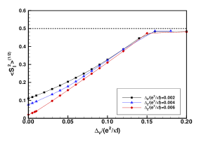
Fig. 10 illustrates the in-plane component for various Zeeman couplings as a function of bias, which we believe is a measure of the NMR relaxation rate, for small . The evident continuous behavior is reminiscent of the Kumada results. We speculate that the effects of finite well width, Landau level mixing, and possibly disorder, all not included in our calculations, may stabilize the CP3 state at higher tunneling than was found for our idealized system.
In conclusion, we have studied textured quantum Hall states in bilayer systems including the spin degree of freedom, and have shown under appropriate circumstances that mixed spin-pseudospin textures appear as the groundstate.
VI Acknowledgements
This work was supported by a research grant (for R.C.) and graduate research grants (for J.B.) both from the Natural Sciences and Engineering Research Council of Canada (NSERC). H.A.F. acknowledges the support of NSF through Grant No. DMR-0454699. K. J. M. and B. R. acknowledge the support of NSF Grants No. DMR-0080054, EPS-9720651 and DMR-0454699. Also B. Roostaei thanks KITP Santa Barbara as part of this work was performed there. R. C. and J. B. thank the Réseau québécois de calcul haute performance for computer time.
References
- (1) S. Das Sarma and A. Pinczuk, Perspectives in Quantum Hall Effects: Novel Quantum Liquids in Low-Dimensional Semiconductor Structures (Wiley, 1996).
- (2) Z.F. Ezawa, Quantum Hall Effects: Field Theoretical Approach and Related Topics (World Scientific, 2000). In this book, the magnetic field while our convention in this paper is that . Thus, our skyrmion has opposite vorticity and real charge from the solution given in this book.
- (3) A. Sawada, D. Terasawa, N. Kumada, M. Morino, K. Tagashira, Z.F. Ezawa, K. Muraki, T. Saku, and Y. Hirayama, Physica E 18, 118 (2003); D. Terasawa, M. Morino, K. Nakada, S. Kozumi, A. Sawada, Z.F. Ezawa, N. Kumada, K. Muraki, T. Saku and Y. Hirayama, Physica E 22, 52 (2004); A. Sawada, Z.F. Ezawa, H. Ohno, Y. Horikoshi, A. Urayama, Y. Ohno, S. Kishimoto, F. Matsukura, and N. Kumada, Phys. Rev. B 59, 14888 (1999).
- (4) I. B. Spielman, L. A. Tracy, J. P. Eisenstein, L. N. Pfeiffer, and K.W. West, Phys. Rev. Lett. 94, 076803 (2005).
- (5) N. Kumada, K. Muraki, K. Hashimoto, and Y. Hirayama, Phys. Rev. Lett. 94, 096802 (2005); N. Kumada, K. Muraki, and Y. Hirayama, Physica E (submitted), 2005.
- (6) S.L. Sondhi, A. Karlhede, S.A. Kivelson, and E.H. Rezayi, Phys. Rev. B 47, 16419 (1993).
- (7) S. E. Barrett, G. Dabbagh, L. N. Pfeiffer, K. W. West, and R. Tycko, Phys. Rev. Lett. 74, 5112 (1995).
- (8) A. Schmeller, J. P. Eisenstein, L. N. Pfeiffer, and K. W. West, Phys. Rev. Lett. 75, 4290 (1995).
- (9) S. Q. Murphy, J. P. Eisenstein, G. S. Boebinger, L. N. Pfeiffer, and K. W. West, Phys. Rev. Lett. 72, 728 (1994).
- (10) Kun Yang, K. Moon, L. Zheng, A. H. MacDonald, S. M. Girvin, D. Yoshioka, and Shou-Cheng Zhang, Phys. Rev. Lett. 72, 732 (1994).
- (11) L. Brey, H.A. Fertig, R. Côté, and A.H. MacDonald, Phys. Rev. B 54, 16888 (1996).
- (12) S. Ghosh and R. Rajaraman, Phys. Rev. B 63, 035304 (2001).
- (13) Z.F. Ezawa, Phys. Rev. Lett. 82, 3512 (1999); Z.F. Ezawa and G. Tsitsishvili, Phys. Rev. B 70, 125304 (2004); Z.F. Ezawa, Physica B 463, 294-295 (2001); Z.F. Ezawa and K. Hasebe, Phys. Rev. B 65, 075311 (2002).
- (14) R. Tycko, S. E. Barret, G. Dabbagh, L. N. Pfeiffer, and K. W. West, Science 268, 1460 (1995).
- (15) R. Côté, A.H. MacDonald, L. Brey, H.A. Fertig, S.M. Girvin, and H. T. C. Stoof, Phys. Rev. Lett, 78, 4825 (1997).
- (16) L. Brey, H.A. Fertig, R. Côté and A.H. MacDonald, Phys.Rev. Lett. 75, 2562 (1995).
- (17) R. Côté and A. H. MacDonald, Phys. Rev. B 44, 8759 (1991).
- (18) H. A. Fertig, Phys. Rev. B 40, 1087 (1989).
- (19) Y. N. Joglekar and A. H. MacDonald, Phys. Rev. B 65, 235319 (2002).
- (20) I. B. Spielman, M. Kellogg, J. P. Eisenstein, L. N. Pfeiffer, and K. W. West, Phys. Rev. B 70, 081303(R) (2004).
- (21) K. Moon, H. Mori, K. Yang, S.M. Girvin, A.H. MacDonald, L. Zheng, D. Yoshioka and S. C. Zhang, Phys. Rev. B 51, 5138 (1995); K. Yang, K. Moon, L. Belkhir, H. Mori, S.M. Girvin, A.H. MacDonald, L. Zheng, and D. Yoshioka, Phys. Rev. B 54, 11644 (1996).
- (22) H. A. Fertig, L. Brey, R. Côté, and A.H. MacDonald, Phys. Rev. B50, 11018 (1994).
- (23) R. Côté, M. Boissonneault and M. Dion. Unpublished.
- (24) L. Brey, H.A. Fertig, R. Côté, and A.H. MacDonald, Physica Scripta, T 66, 154 (1996).
- (25) Y. V. Nazarov and A. V. Khaetskii, Phys. Rev. Lett. 80, 576 (1998).
- (26) Z.F. Ezawa, Phys. Rev. B 55, 7771 (1995).
- (27) S. Ghosh and R. Rajaraman, International Journal of Modern Physics B 12, 2495 (1998); ibid. p. 37.
- (28) R. Côté et al. Unpublished.