temporary address:]Russell S. Springer Professor - University of California, Berkeley, CA 94720-1740, USA
present address:]Cornell University, Ithaca, NY USA
A high-reflectivity high-Q micromechanical Bragg-mirror
Abstract
We report on the fabrication and characterization of a micromechanical oscillator consisting only of a free-standing dielectric Bragg mirror with high optical reflectivity and high mechanical quality. The fabrication technique is a hybrid approach involving laser ablation and dry etching. The mirror has a reflectivity of 99.6%, a mass of 400ng, and a mechanical quality factor Q of approximately . Using this micromirror in a Fabry Perot cavity, a finesse of 500 has been achieved. This is an important step towards designing tunable high-Q high-finesse cavities on chip.
Micromechanical oscillators are today widely used in applications from thermal, infrared and chemical to biological sensing Sensors . This huge success is due to the fact that sensors based on micro cantilevers can detect extremely small stimuli such as temperature and mass changes as well as small external forces Ekinci_2005 . Available devices can be placed in two categories based on their readout scheme. Micro electro-mechanical systems (MEMS) use a wide array of electronic coupling schemes to transduce mechanical energy into electronic signals, while micro opto-mechanical systems (MOMS) are usually read out using an optic lever or a Fabry Perot interferometer. For MOMS, the sensitivity or coupling strength is mainly dependent on both the mechanical quality and the reflectivity of the cantilever. By increasing the mechanical quality factor and using ultra-high reflectivity materials one can thus considerably increase the performance of such sensors. Ultimately, when all technical noise sources have been eliminated, quantum mechanics poses a limit in the sensitivity of such devices WeakForces . Although in today’s sensor applications this quantum limit has not yet been reached Millburn , a very close approach has been demonstrated Lahaye ; Hadjar .
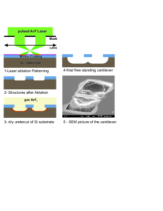
While the reflectivity of a bulk dielectric or semiconductor material is, in general, quite low (typically around 50%), reflectivities of up to 98% can be achieved by depositing a thin metallic layer on top of predefined structures. If higher reflectivities are needed one has to use Bragg mirrors which consist of a stack of thin layers of materials with different refractive indices. Such mirror materials are widely used and can reach reflectivities larger than 99.999% or, when used as mirrors in an optical cavity, a cavity finesse of . High reflectivities have been achieved in MEMS tunable Fabry-Perot etalons, however with a very low mechanical quality Q typically well below 10 Tucker . In this paper we report the fabrication and characterization of a high-quality mechanical beam oscillator consisting of a free-standing Bragg mirror with reflectivity and of high mechanical quality . In contrast to previous approaches, where the reflectivity of Si-microstructures is increased by coating them in a postprocessing step, we directly fabricate the microstructure out of a large-scale Bragg-mirror (See figure 1). This avoids the unwanted side effects that typically arise during the coating procedure, such as bending due to thermal mismatch Stressdielectric . The fabrication technique is based on pulsed-laser ablation of the coating, followed by dry-etching of the substrate underneath. Laser ablation is an interesting technique complementary to standard micro-fabrication methods, since, unlike wet etching or reactive ion etching, it does not depend on the chemical reactivity of the material being patterned Bauerle ; Schafer . Furthermore, the good spatial selectivity achieved with short laser pulses allows the local removal of material while it preserves the coating quality on the oscillator.
The low selectivity on material at high laser fluences allows ablation of thick dielectric stacks of materials with different chemical properties. The good control of the ablation depth permits well-defined removal of the coating. To free the structure from the substrate, a very selective dry-etching method was employed. It undercuts the patterned coating but does not etch it in any measurable manner. Following the description of the fabrication method we present the experimental setup to characterize the optical and mechanical quality of the resulting structure. Subsequently we give a short summary and discussion of the obtained results.
The fabrication of the micromirrors starts from a standard polished silicon wafer on which 16 layers of and have been deposited to form a highly reflective (HR) Bragg mirror. This process, which has been optimized to reduce tensile stress, was done by the coating company O.I.B.GmbH. The nominal reflectivity is 99.8% at a wavelength of 1064 nm.
Subsequently the coated wafer is patterned using laser ablation by projecting 193 nm ArF-laser radiation ( 1.3 , ns, repetition rate 1 to 10 pps) via a mechanical mask (reduction optics 10:1). With the laser pulse length employed, the heat affected zone (HAZ) was about 5 . This is in reasonable agreement with estimates of lateral heat diffusion in the silicon substrate Bauerle . To protect the mirror from debris generated during laser ablation, the surface is coated with a thin layer of a soft-baked photoresist (Shipley S1813). After ablation this layer is dissolved in an ultrasonic bath of acetone. By putting the sample in a atmosphere the exposed Si substrate is etched rapidly Chang (1 / min) isotropically and very selectively in the ablated regions around and below the beam. The / selectivity of the etch is better than 1000:1 Manufact , and there is no measurable etch of TiO2, which is the top layer of the coating. The etching is optically monitored in-situ, and is stopped as soon as the beam is fully underetched. The final structure consists of a free-standing beam of approximately 520 length and a width of 120 , which is made only out of the original 2.4 thick Bragg-mirror coating surrounded by a membrane of about half of its width. The total mass of the beam, as calculated from its dimensions, is about 400ng. The uneven undercut of the structure depicted in figure 1 is most probably due to partial coverage of the silicon surface with other materials. Possible sources of contamination are incomplete ablation, redeposition of ablated material or oxidation of the heated silicon surface in air, all of which can be avoided by ablating the coating in vacuum or deeper ablation.
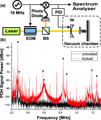
The micro-mirror was characterized via Fabry-Perot interferometry. We built a linear Fabry-Perot optical cavity with the beam as the highly-reflecting end mirror on one side and a massive input coupler mirror on the other side (see figure 2). The input-coupler is a concave mirror with radius of curvature R = 25mm and a reflectivity of 99.4% for 1064nm radiation. The cavity was slightly shorter than 25 mm. The chip containing the micro-mirror was placed on a 3-axis translation stage for alignment and the optical beam was positioned on the oscillator. The size of the waist of the mode of the cavity is around 20 , which is much smaller than the width of the beam. The input mirror is placed on a piezoelectric transducer (PTZ)respectively to scan the length of the cavity. The whole cavity is placed in a vacuum chamber with a pressure of mbar to avoid damping of the oscillations of the beam due to air friction. All experiments were performed at room temperature.
For readout, the cavity is locked via the Pound-Drever-Hall (PDH) method pdh . The PDH locking signal is sent to a PID controller, the output of which is sent to the PZT to control the fine length of the cavity at resonance (Fig.3). It is known that the intensity of the PDH error signal around resonance is proportional to the change in length of the cavity. As a consequence, the vibrational noise of the beam can be monitored with high accuracy via the spectrum of the PDH error signal pdhmeasurement . The optical quality is characterized by measuring the finesse F of the cavity, which is related to the round-trip intensity loss via in the limit of a high-finesse cavity. We measured a finesse of 650 at non-undercut regions of the mirror and of around 500 on the beam, corresponding to overall round trip losses of 1% and 1.3% respectively (This includes the 0.6% insertion losses on the input coupler). To determine the reflectivity of the coating, we build a cavity using a region of the coating that is spaced a few mm from the ablated structures. In this regions we obtain a reflectivity of 99.6% (i.e. a minimal degradation from the nominal value). The additional losses of 0.3% on the beam can be explained both by diffraction losses and by imperfections introduced during laser ablation, in particular near the edges of the beam.
The mechanical quality factor is obtained via the frequency spectrum of the PDH signal while the cavity is locked at resonance with the input laser frequency. Several mechanical resonance peaks can be detected within the range of 200 kHz to 5 MHz. Their frequencies match well with finite elements (FE) simulations of transverse vibrational modes (i.e. oscillations occur normal to the surface) of a doubly clamped beam under tensile stress, specifically of a fundamental mode at 278kHz and its harmonics. We observe an additional splitting of each transverse mode into two modes separated by a few kHz, which can be identified as modes with different torsional contributions.
A critical parameter for performing high-sensitivity measurements with movable micro-mirrors is their mechanical quality factor Q, which is a direct measure for the time scale of dissipation in an oscillating system. Q is defined as the ratio between the resonance frequency and the full width at half maximum (FWHM)correspond to of the resonance peak. It is a crucial parameter for sensors as it limits the sensitivity of all measurements. We isolated the lowest resonance at 278 kHz, which corresponds to the fundamental transverse mode of the beam. The measured Q-factor of this mode was around 9000, with a FWHM of around 32Hz. The Q-factor of higher-order modes decreases monotonically to around 2000 for the fourth transverse mode at 1.2MHz, which is indicative for the presence of clamping losses (see for example Ekinci_2005 and references therein). One should finally note that our method is not limited to the present parameter range but can in principle yield much higher reflectivity and Q. For example, the reflectivity can be increased by employing sophisticated state-of-the-art HR coatings as are typically used for gravitational wave detectors (yielding reflectivity of up to 99.9999%). Another possibility is to use Silicon-On-Insulator (SOI) technology instead of plain silicon wafers. The dry etch would then undercut only the device layer and stop on the buried oxide. This could lead to more kinetically controlled etching, i.e. to a better control of the membrane uniformity, and hence to a more controlled resonance frequency and higher Q factor.
In conclusion, we have demonstrated a promising method for the fabrication of micromechanical mirrors with high reflectivity, high mechanical quality, and low mass. Such a Bragg mirror is the lightest HR beam that one can design since the coating itself constitutes all the mass. We have characterized its mechanical and optical properties by using this micro-mirror in a Fabry-Perot interferometer. The reflectivity of the mirror is in principle limited only by the intrinsic coating quality. The combination of high reflectivity, low mass and high mechanical quality make the fabricated micro-mechanical mirrors an excellent candidate for high-sensitivity measurements down to the quantum limit. In addition, such structures may provide the possibility to study genuine quantum effects involving mechanical systems Mancini94 ; Bose97 ; Marshall03 ; Pinard05 .
Acknowledgements.
We would like to thank Heidi Piglmayer-Brezina for fabricating the masks for the laser ablation. We acknowledge financial support by the Austrian Science Fund (FWF) under the programs SFB15 and P16133-N08, by the Austrian NANO Initiative (MNA), by the European Commission under the Integrated Project Qubit Applications (QAP) funded by the IST Directorate under contract number 015846, by the Foundational Questions Institute (FQXI) and by the City of Vienna.References
- (1) T. Thundat and Arun Majumdar, in ”Sensors and Sensing in Biology and Engineering”, Springer (2003)
- (2) K. L. Ekinci and M. L. Roukes, Rev. Sci. Instr. 76, 061101 (2005)
- (3) V.B. Braginsky , A.B. Manukin, Univ. of Chicago Press (1977)
- (4) G. J. Milburn, K. Jacobs, and D. F. Walls, Phys. Rev. A 50, 5256 (1994).
- (5) M. D. LaHaye, O. Buu,B. Camarota, K. Schwab, Science 304(5667), 74?77 4 (2004).
- (6) Y. Hadjar, P. F. Cohadon, C. G. Aminoff, M. Pinard, A. Heidmann, Europhys. Lett, 47 (5), pp. 545-551 (1999)
- (7) R.S. Tucker, D.M. Baney, W.V. Sorin, C.A. Flory - IEEE Journal of selected topics in Quant. Elec. (2002)
- (8) H. Kupfer, T. Fluegel, F. Richter, P. Schlott, Surface and Coatings Technology 116-119 (1999)
- (9) D. Bäuerle, Laser Processing and Chemistry (Springer, 2000), 3 edn.
- (10) D. Schaefer, J. Ihlemann, G. Marowsky, P.R. Herman, Appl. Phys. A, 72, 377-379 (2001)
- (11) Floy I. Chang, Richard Yeh, Gisela Lin, Patrick B. Chu, Eric G. Hoffman, Ezekiel J. Kruglick, Kristofer S. J. Pister, and Michael H. Hecht, Proc. SPIE Int. Soc. Opt. Eng. 2641, 117 (1995)
- (12) Manufacturer private communication
- (13) R. W. P. Drever, J. L. Hall, F. V. Kowalski, J. Hough, G. M. Ford, A. J. Munley, H. Ward, Applied Physics B, 31, 97 (1983)
- (14) K. Jacobs, I. Tittonen, H.M. Wiseman, S. Schiller, Phys. Rev. A 60, 538 (1999)
- (15) S. Mancini and P. Tombesi, Phys. Rev. A 49, 4055–4065 (1994)
- (16) S. Bose, K. Jacobs and P. L. Knight Phys. Rev. A 56, 4175-4186 1997
- (17) W. Marshall, C. Simon, R. Penrose, D. Bouwmeester, Phys. Rev. Lett. 91, 130401 (2003)
- (18) M. Pinard, A. Dantan, D. Vitali, O. Arcizet, T. Briant, A. Heidmann, Europhys. Lett. 72, 747 (2005)