Microwave Heating of Water, Ice and Saline Solution: Molecular Dynamics Study
Motohiko Tanaka, and Motoyasu Sato
Coordinated Research Center, National Institute for Fusion Science, Toki 509-5292, Japan
Abstract
In order to study the heating process of water by the microwaves of 2.5-20GHz frequencies, we have performed molecular dynamics simulations by adopting a non-polarized water model that have fixed point charges on rigid-body molecules. All runs are started from the equilibrated states derived from the Ic ice with given density and temperature. In the presence of microwaves, the molecules of liquid water exhibit rotational motion whose average phase is delayed from the microwave electric field. Microwave energy is transferred to the kinetic and inter-molecular energies of water, where one third of the absorbed microwave energy is stored as the latter energy. The water in ice phase is scarcely heated by microwaves because of the tight hydrogen-bonded network of water molecules. Addition of small amount of salt to pure water substantially increases the heating rate because of the weakening by defects in the water network due to sloshing large-size negative ions.
PACS Numbers: 77.22.Gm, 52.50.Sw, 82.20.Wt, 82.30.Rs
I Introduction
It is well known that microwaves (300MHz - 300GHz range) can heat solid, liquid and gaseous matters such as engineering materials, laboratory plasmas, and biological matters including living cells. A microwave oven used in daily food processing is one of such applications. However, unlike laser lights whose photon energy is from several to tens of electronvolts, the photon energy of microwaves is as small as eV and their period is by orders of magnitude longer than the electronic processes (a few fs) occurring in molecules. Nevertheless, microwaves can control chemical reactions, synthesize organic and inorganic materials kappe ; appl-syn , and sinter metal oxides with high energy efficiency Roy . Thus, for the microwave-related heating and reactions to take place, non-resonant interactions between waves and materials that persist for many wave periods are expected.
The physical and chemical properties of matters are the basis of material science, engineering and biological applications. Especially, the dielectric permittivity was measured extensively as the function of electromagnetic wave frequency and temperature data-hip , and precise experimental formulas were presented for the dielectric properties of water, including enhanced heating of salty water water-diel . The imaginary part of the dielectric permittivity is related to the energy absorption by dielectric medium, which is termed as dielectric loss. For water, the rotational relaxation of permanent electric dipoles occurs approximately in 8ps at 25∘C (frequency of 120GHz) dip-relax . For the microwaves less than and around this frequency, only translational and rotational motions of polar molecules are expected to respond to the waves.
The diffusion coefficients and dielectric relaxation properties of water, i.e. the response of electric dipoles to a given initial impulse, were studied theoretically hirata . Numerically, the melting of ice at normal pressure was investigated with several water models melting . The heating and diffusion of water under high-frequency microwaves and infra-red electromagnetic waves were investigated by molecular dynamics simulations using elaborated point-charge models that incorporated either charge polarization or molecular flexibility for the system of 256 water molecules Eng1 ; Eng2 . Precise studies showed that the polarizable water model TIP4P-FQ combined with the Lekner method gives more accurate results than fixed-charge model, including the potential energy, dipole moment, dielectric constant and relaxation times Eng3 . However, the polarizable model requires large computation times, roughly three times more than fixed-charge models with the Ewald method for 256 water molecules. It becomes progressively more demanding as O() with the increasing number of molecules compared to O() of the Ewald method. Since we treat large systems with 2700 water molecules with or without salt ions, we adopt the non-polarized water model SPC/E combined with the Ewald method, which yields rather qualitative but reasonable results for electrostatic properties.
Complementary to the previous studies, we examine the heating of water by low-frequency microwaves in typical phases, including liquid water, ice and dilute saline solution, by means of classical molecular dynamics simulations MD-DNA . We use the microwaves in the 2.5-20GHz frequency range and the field strength of 0.01V/Å, and a relatively large system containing 2700 water molecules. As we focus on the heating process in the low frequency and low field strength regime, we adopt a fixed point-charge, rigid-body model for water and a constant volume periodic system without an energy or particle reservoir. As for the diagnosis, we directly measure the kinetic and potential energies to obtain transferred energies from the microwaves.
We have confirmed that water in the liquid phase is heated by microwaves through the excitation of rotational motion of permanent electric dipoles of water molecules which is delayed from the wave electric field. The microwave energy is transferred to kinetic and internal (inter-molecular) energies of water, where the energy stored as the internal one amounts to about one third that of the total absorbed power. Dilute salt water is heated significantly more rapidly than pure water because of the weakening of hydrogen-bonded water network due to large-size salt ions including Cl-. On the other hand, the water in ice phase is hardly heated by low-frequency microwaves, since electric dipoles exhibit substantial directional inertia due to the rigid network of water molecules.
This paper is organized as follows. In the next section, the simulation method and parameters adopted in this study are described. In Sec.3, our simulation results of microwave heating are presented for three typical cases including ice, liquid water and salt-added water. Sec.4 will be a summary of this paper.
II Simulation Method and Parameters
To study the heating process of water, we use the microwaves of the frequency range 2.5-20GHz, whose wavelengths and periods are 1.5-12cm and 50-400ps, respectively. These scale-lengths are much larger than our model water system whose edge length is approximately 40Å in one direction (typically one molecule resides in every 3Å). Also, all the involved velocities are much less than the speed of light (). Under such circumstances, we can safely assume with the motion of water molecules and salt ions that the microwave is represented by spatially uniform, time alternating electric field of the form
| (1) |
For the purpose of our study mentioned above, the water in liquid and ice phases is approximated by the assembly of three-point-charge rigid-body molecules known as the SPC/E model SPC . These molecules are placed in a constant volume cubic box. In this model, fractional charges are distributed at the hydrogen sites and at the oxygen site, where with the electronic charge. The -th atom of the water molecule moves under the Coulombic and Lennard-Jones forces
| (2) | |||
| (3) |
where and are the position and velocity of the -th atom, respectively, , and are its mass and charge, respectively. For the Lennard-Jones potential between interacting -th and -th atoms, the combination rules
| (4) |
are used where and are the diameter and Lennard-Jones potential depth of the -th atom, respectively. In Eq.(2), the Lennard-Jones force is calculated only for the oxygen atoms with 3.17Å and 0.65kJ/mol. The length of the hydrogen-oxygen bond is 1.00Å and the angle between these bonds is 109.47 degrees. The constraint dynamics procedure called ”Shake and Rattle algorithm” shake is used to maintain these bond length and angle. Salt Na+Cl- is added in some runs. The Lennard-Jones forces are calculated for the pair of the ionic atom and oxygen atom of water molecules, where the diameter and the Lennard-Jones potential depth used for Na+ are 2.57Å and 0.062kJ/mol, respectively, and those for Cl- are 4.45Å and 0.446kJ/mol, respectively.
As for the initial conditions, we use highly structured crystal ice Ic with 14 molecules in all three directions under given density 1.00g/cm3 for liquid water (the edge length of the cubic box is fixed at 43.448Å), and 0.93g/cm3 for ice (44.512Å). Thus, we have approximately 2700 water molecules in the box with periodic boundary conditions. Water molecules, especially those of ice and liquid water, form a three-dimensional network with hollow unit cells consisting of six-membered water rings ohmine . The connection between the molecules is made by the hydrogen bond between a hydrogen atom and an adjacent oxygen atom that belongs to a different molecule. Each molecule donates two hydrogen bonds to adjacent molecules and accepts two hydrogen bonds from other molecules to form the hydrogen-bonded network, thus there is a freedom to which neighboring molecules two hydrogen atoms are donated from one molecule. The initial orientations of water molecules are prescribed such that the directions of two hydrogen atoms bonded to an oxygen atom are swapped under the Ic symmetry until the sum of the bonded O-H vectors is nullified for each of all three directions; the number of water molecules in any direction must be an even number iceIc , which is 14 for the system length 44.512Å. All simulation runs are preceded by an equilibration phase of 100ps at given temperature and density before microwaves are applied.
The calculation of the Coulombic forces under the periodic boundary condition requires the charge sum in the first Brillouin zone and their infinite number of mirror images (the Ewald sumEwald ). The sum is calculated with the use of the particle-particle, particle-mesh algorithm and the procedure of minimizing the rms error in the force Eastwood ; Deserno . We use spatial meshes and the 3rd order spline interpolation for the calculation of the reciprocal space contributions to the Coulombic forces, and take direct summations for the short-range particle-particle forces with the real-space cutoff 10Å and the Ewald screening parameter Å-1. This yields the maximum rms error in the force . We note that the accuracy of the Ewald sum can be optimized with the Lekner method for highly ionic environments at the expense of computation times Eng5 . The time integration step is 1fs, for which the detection level of heating for liquid water is /ps. We use our PC cluster machines, each of which consists of four Pentium 4/EM64T (3.4GHz) processors, and a 500ps run takes typically 48 hours.
Three types of runs are performed, namely, (i) ice of the Ic form at 230K, (ii) pure water whose initial temperature is 300K, and (iii) salt water with 1mol% NaCl (3.2wt% or 0.57M) starting at 300K. In numerical simulations, we use large electric fields in order to detect heating in a reasonable computation time, which is typically V/cm. Nevertheless, this is not a large electric field when viewed from water molecules, since the dipole energy eV (esu cm is the electric dipole of our model water) is still less than thermal energy eV at room temperature K, where is the Boltzmann constant. The dipole energy is by orders of magnitude less than the hydrogen-bond energy 2.5eV per bond.
III Simulation Results
In the following sections, unless otherwise specified, we use the microwaves of the frequency 10GHz (period 100ps) and the strength V/cm, which corresponds to the ratio of the dipole energy and thermal energy at K, .
III.1 Heating of Crystal Ice
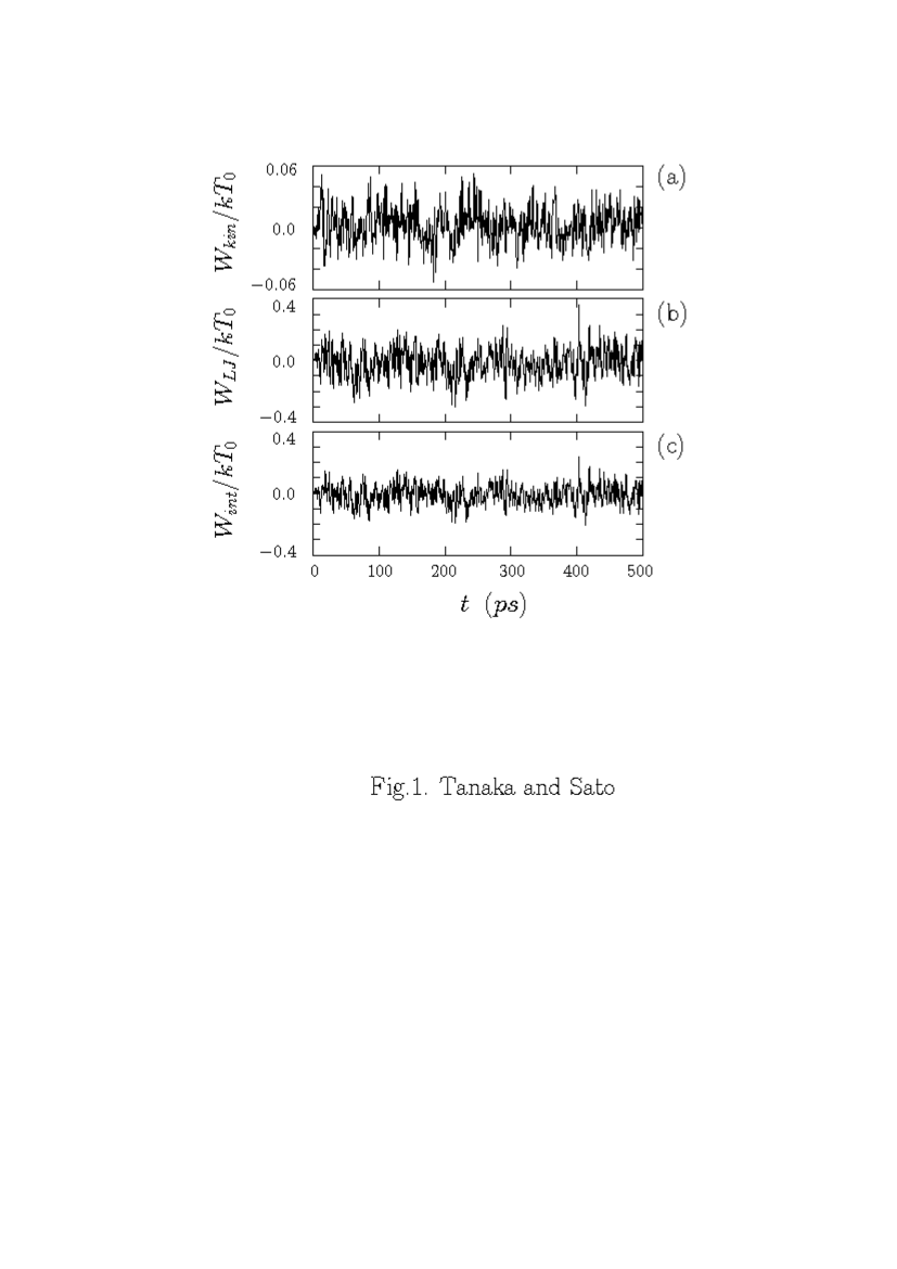
The microwave heating of water in ice phase is examined for the crystal ice Ic at the temperature 230K. Figure 1 shows the time history of average quantities: (a) the kinetic energy of water molecules , which includes both translational and rotational energies, (b) the Lennard-Jones energy, , and (c) the inter-molecular energy, which is the sum of the Lennard-Jones energy and the Coulombic energy , where the prime means the summation excluding the charge pairs on the same molecule. The kinetic energy above is the index of heating, and the maximum and minimum of Fig.1(a) correspond to 2307K, respectively. Despite the microwave application for , the kinetic and inter-molecular energies remain nearly constant except for small periodic fluctuations.
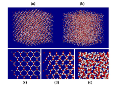
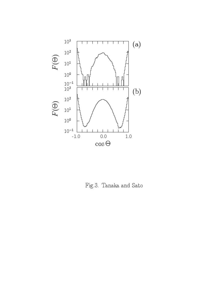
The geometrical arrangement of water molecules is shown in Fig.2 at the final time =500ps for (a) ice at 230K, (b) liquid water initially at 300K (to be mentioned in Sec.IIIB), and (c)-(e) their enlarged plots of the edge parts. The water in ice phase of Fig.2(c) has a complete crystal structure, which remains nearly intact after the microwave application as seen in Fig.2(d) and (a). The distribution functions of electric dipoles of water molecules for the ice in terms of the directional cosine
| (5) |
are shown in Fig.3, which also stay almost unchanged during the microwave application (the ordinate is in a logarithmic scale), where is the electric dipole of the -th molecule, is the unit vector in the direction. This immobility of electric dipoles is attributed to the rigidity of the network of water molecules due to hydrogen bonds. These observations indicate that pure crystal ice is not heated by microwaves of a few GHz frequency at the applied intensity. On the other hand, methane hydrates were found to be raptured by microwave fields at higher intensities Eng4 .
III.2 Heating of Liquid Water
Now we examine the microwave heating of water in the liquid phase starting at the temperature 300K. In the cubic box there are 2744 water molecules which have been equilibrated without the microwave field at this temperature.
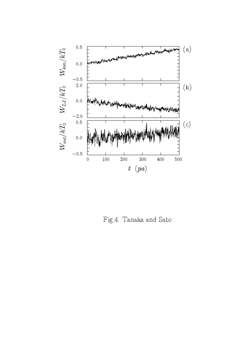
The depiction of molecular arrangement of Fig.2(b) and (e) at ps after microwave application clearly shows that the water molecules in the liquid phase are randomized both in guiding center positions and molecular orientations by absorbing microwaves. Figure 4 shows the time history of (a) the kinetic energy of water molecules, (b) the Lennard-Jones energy, and (c) the sum of the Coulombic and Lennard-Jones energies. When microwaves are switched on at t=0 in Fig.4, the kinetic energy of water molecules begins to increase at a constant rate; the final temperature is 350K. The average distance between the molecules is expanding during this rearrangement of molecules (the energy minimum of the Lennard-Jones potential is located at 3.56Å). We note that the water at rest is in a minimum energy state because of strong attraction forces due to hydrogen bonds. The decrease in the Lennard-Jones energy and the increase in the Coulombic energy take place simultaneously under the microwave field, but the latter is larger than the former, thus the inter-molecular energy increases. The microwave energy is transferred to kinetic and inter-molecular energies of water, where the latter is about 35% that of the total absorbed power, as seen by comparing Fig.4(a) and (c).
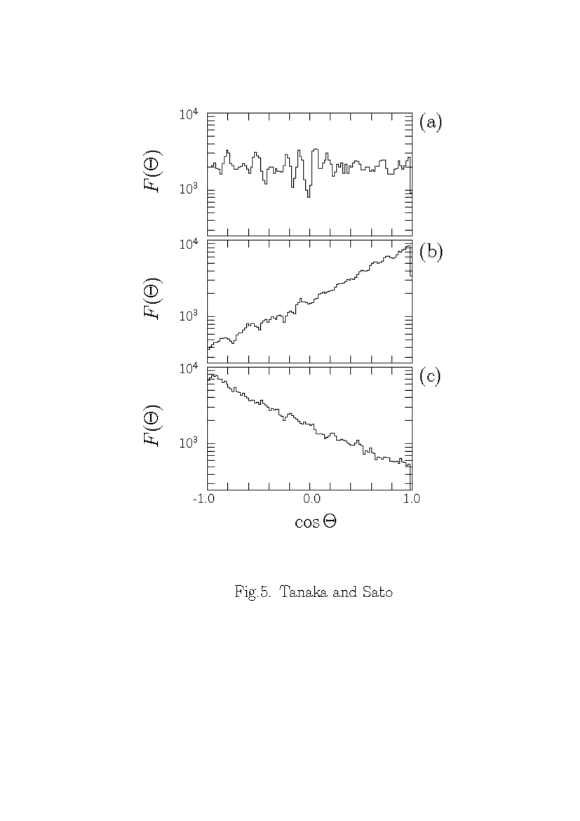
The observed heating is attributed to the excitation of the rotational motion of permanent electric dipoles of water molecules and simultaneous energy transfer to translational energy via molecular collisions. Angular distributions of electric dipoles as the function of the directional cosine of their orientation are shown in Fig.5 in 50ps intervals. Before the microwave application, the electric dipoles in Fig.5(a) have random orientations at room temperature. When the microwave electric field is present, the dipoles align along the direction of the time-alternating electric field , as seen in Fig.5(b) and (c). At each instant, the angular distribution of electric dipoles nearly follows the statistical (Boltzmann) distribution,
| (6) |
with regard to the angle , where is the dipole energy and the normalization constant is .
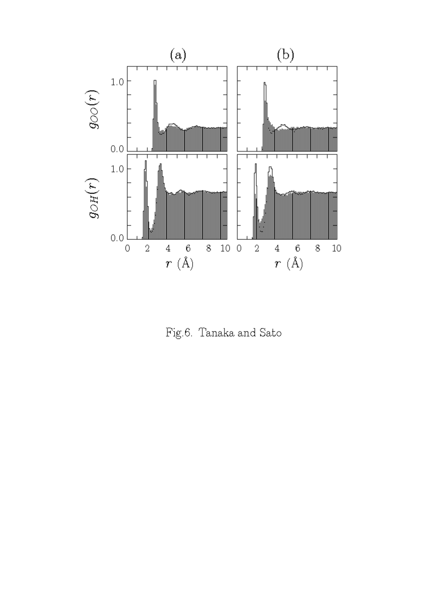
The radial distribution function (RDF) between oxygen atoms for liquid water in Fig.6(a) reveals that the initial gap located at 3.5Å is filled after the microwave application. The gap at 2.5Å in the RDF between hydrogen and oxygen atoms is also partially filled. These observations indicate the randomization of the orientation of electric dipoles and the increase in the distances between oxygen atoms. They are consistent with the increase in the Coulombic energy , where the major contribution comes form the hydrogen and oxygen pairs due to hydrogen bonds.
However, it should be noted that a finite phase difference is required between the orientation of electric dipoles of water molecules and the electric field for the energy to be transferred from microwaves to water. The sum of the -component of electric dipoles is obtained by
| (7) | |||
where we have used Eq.(6) and expanded it assuming (the next order term is , which is a few percent of the above leading term even for ). Then, we put the electric dipole with the phase lag . The work done to the dipoles at the position per unit time by the electric field Eq.(1) is,
| (8) | |||
If we assume the Debye-type relaxation and , where is the friction from adjacent water molecules water-relax , then we have
| (9) |
This formula indicates that, without friction , the phase lag vanishes , thus we have no microwave heating of water.
The heating and energy absorption rates of liquid water at 300K by the microwaves of f= 10GHz and V/cm are /ps and /ps, respectively (Table I). The expected energy absorption rate using the experimentally obtained imaginary part of the dielectric constant is erg/ps/molecule /ps/molecule, where molecules/cm3. This estimate is in fair agreement with the simulation value of the energy absorption rate. Further, by equating Eq.(8) and the energy absorption rate in the simulation, then we have the estimate for the phase lag as ps.
The total energy absorption rate by the water system may be obtained by integrating the local energy absorption rate over the depth (-coordinate). Since the wave electric field attenuates as in dielectric medium, then we have
| (10) |
where , and is the electric field at the interface (inside) of water. The length is a few cm for 2-10GHz microwave in water. For the power dependence on the electric field , the integration yields the same power dependence even when by substituting of the local formula by .
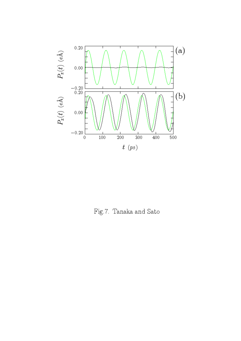
Existence of the phase-lag is verified in Fig.7 which shows the temporal phase variations of the -component of the average water electric dipole and the electric field, for (a) ice at 230K and (b) liquid water initially at 300K. For the ice case, variations of the electric dipoles are very small. For the liquid water, on the other hand, we see large oscillations in the -component of electric dipoles. Their amplitude is almost the value expected by Eq.(7), and a finite phase difference exists between the electric dipole and the electric field. The phase-lag of electric dipoles from the microwave electric field is about 12ps on average. This is about two third that of the phase lag obtained above using Eq.(8), but is close to the rotational relaxation time 8ps of water dipoles at 25∘C, and a fraction of the macroscopic relaxation time 40ps (25GHz) of bulk water wat-relax .
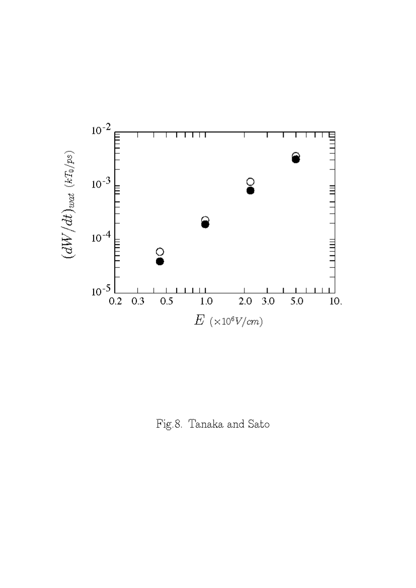
The dependence of the energy transfer rate to liquid water on the strength of the microwave electric field is shown in Fig.8, for the temperature 300K and the wave frequency 10GHz. Here, the time rate of the increase in the kinetic energy is plotted by filled circles, and that in the total energy (the sum of the kinetic and inter-molecular energies) is plotted by open circles, with both axes in logarithmic scales. These two energy transfer rates from the microwaves increase by power laws of the microwave electric field, and are scaled as
| (11) |
with both for the wave power absorbed by the water system and the kinetic energy of water. We note that about 30% of the absorbed microwave energy is stored as the inter-molecular energy to rearrange water molecules. These dependences on the electric field agree with that given by Eq.(9).
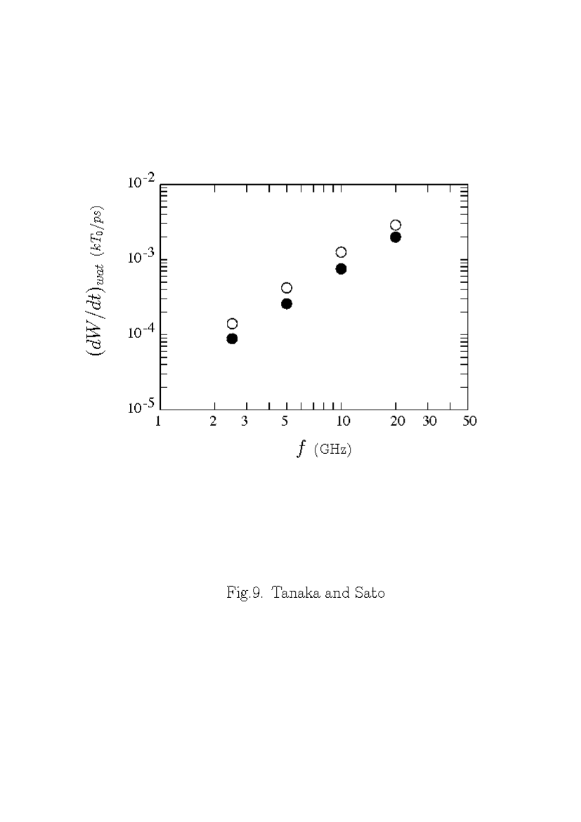
The dependence of the energy transfer rate on the frequency of microwaves is shown in Fig.9, where the frequency is in the = 2.5-20GHz range. The transferred energy from the microwaves increases with the wave frequency, and are scaled by
| (12) |
with both for the total energy absorbed by the water system and for the kinetic energy of water molecules. These frequency dependences are somewhat weaker than that of the formula Eq.(9), as the approximation may deteriorate at high frequencies.
In Table I, the heating rates that we have measured by numerical simulations of the ice and liquid water at two initial temperatures are listed, together with that for the salt water (to be mentioned in Sec.IIIC). The heating rate for the ice is below our detection level. The heating rate of hot water at 400K (in liquid phase, because of the constant volume) is small and only a fraction in comparison with that at room temperature. This is due to less friction at higher temperatures, since the inter-molecular distances of water molecules become large. The simulation value is consistent with the experiment data-hip .
III.3 Heating of Salt Water
We examine the heating process of dilute saline solution, which corresponds to our daily applications including the heating of salty food in a microwave oven. In the simulation, we place 27 Na+ and 27 Cl- ions (1mol% NaCl or 3.2wt% salinity) at random positions to the water system at room temperature. The number of water molecules here 2717 is less than that of the pure water case with the same volume to avoid overlap of salt ions and water molecules. We equilibrate the solution for 100ps before the microwave application at .
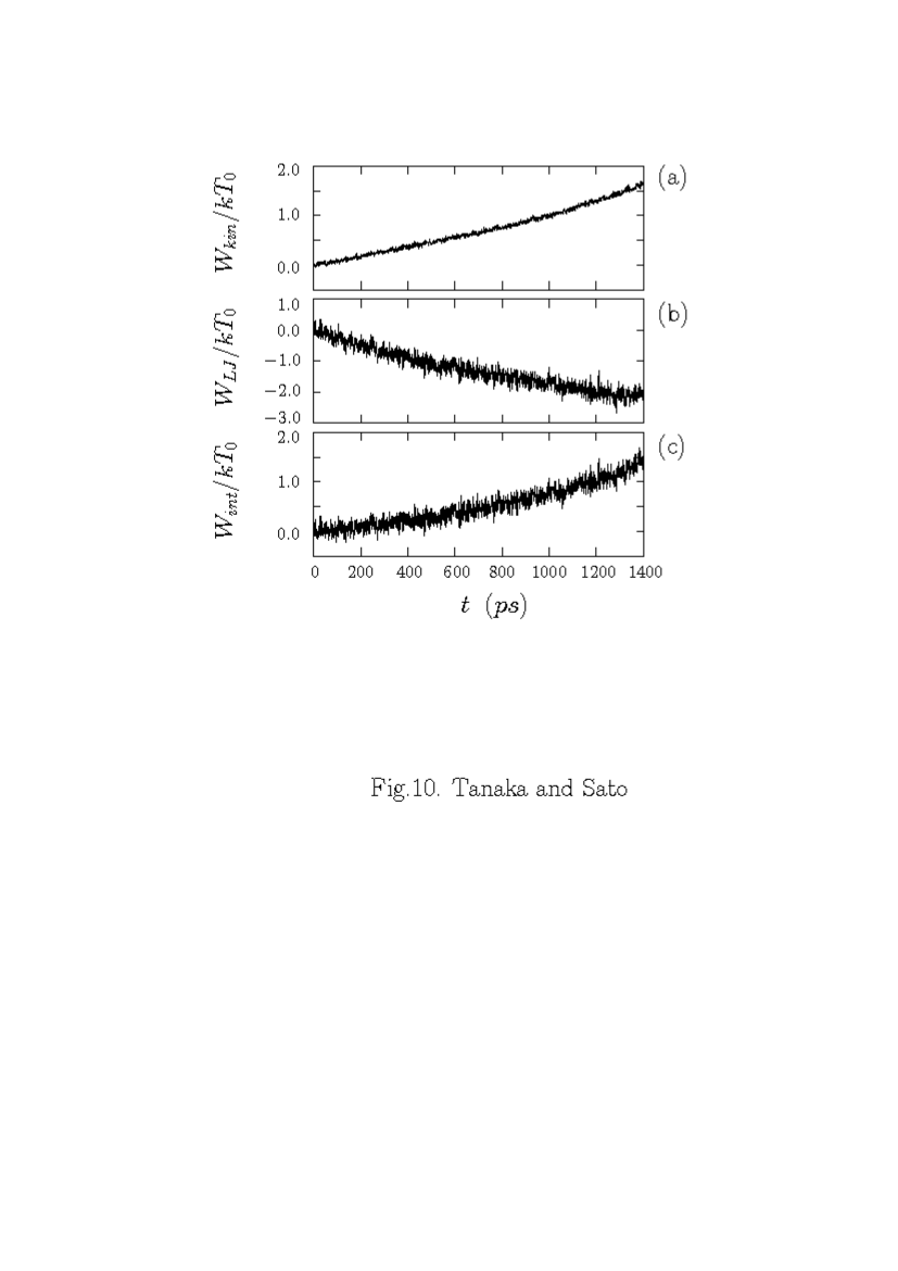
Figure 10 shows the time history of salt water heating by microwaves of 10GHz and the field strength V/cm (). The kinetic energy of water molecules increases only slightly faster (11%) than for pure water in the early stage. After a waiting time of 0.8ns, a rapid heating phase sets in and the salt water is heated by a few times better than the pure water. The length of this microscopic waiting time among the runs with different microwave field strength is not indexed to the water temperature at which the rapid heating sets in. The microwave power is absorbed also as the inter-molecular energy, which is comparable to the increase in the kinetic energy (Fig.10(c)).
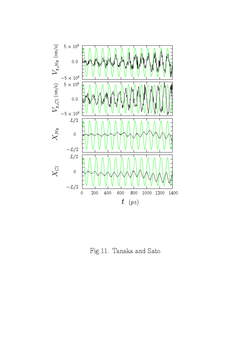
The behavior of salt ions in saline solution after the microwave application is shown in Fig.11. Both the cations and anions are accelerated by the electric field, and the envelops (maximum values) of their average velocities expand continuously in time. Their acceleration is nearly in-phase and out-of-phase with the microwave field for cations and anions, respectively. Interestingly, the degree of the acceleration is appreciably larger for the heavier and larger anions than cations. This fact may be due to that small-size cations are well contained in the water network compared with anions whose diameter is comparable to the cell size of the network (this point is to be mentioned in the RDF of salt ions in Fig.12). The mean displacements of salt ions in Fig.11 shows that anions shift toward the negative -direction and its amplitude is larger than that of cations which shift to the positive -direction. We note that the amount of the positional shift for anions increases linearly up to 0.8ns. At the end of this period when the rapid hating phase begins, the positional shift is roughly 7Å which is comparable to the unit cell size of the water network consisting of hydrogen-bonded six-membered rings. This reveals that the rapid heating of saline solution is connected with sloshing of anions among the neighboring cells.
The velocity distribution functions along the direction of the microwave electric field has been examined for salt ions in saline solution. Unlike the solids such as zeolites and titanium oxides Eng5 ; zeolite , the velocity distribution function consists of a single Boltzmann distribution and supra-thermal component has not been detected under the wave frequency and intensity of the present study.
The radial distribution functions (RDF) of oxygen-oxygen pairs and those of oxygen-hydrogen pairs are shown for the above salt water in Fig.6(b). Initial RDFs are shown by solid lines and those at the final times are shown by shaded histograms. We see drastic differences between the RDFs before and after the microwave application. The height of the first peak at 1.9Å in and that at 2.8Å in are much reduced, and the gaps between the first and second peaks are filled. This reveals the randomization of the position and orientation of water molecules, and thus weakening of the water network.
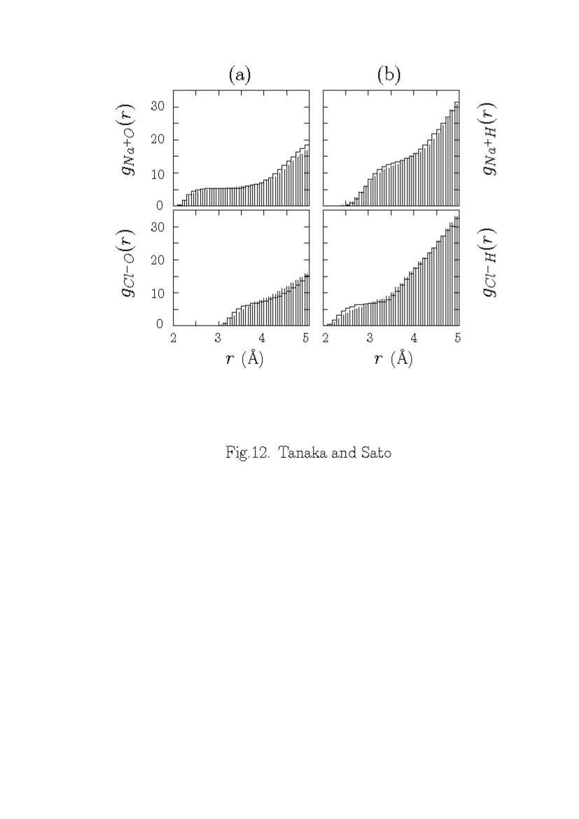
The accumulated RDF for the oxygen-hydrogen pairs at the initial time has a flat pedestal, from which the association number of a hydrogen atom to oxygen atoms is approximately two at 2Å. At 1.4ns, the inner edge of the accumulated RDF is receded for oxygen-hydrogen pairs. The accumulated RDF of the Na+ ions in Fig.12 shows that they are associated with five oxygen atoms at 2.5Å which changes only slightly during the microwave application. This means that Na+ ions are well contained in the unit cell of the water network, as previously mentioned. On the other hand, shows that a Cl- ion is loosely associated with seven oxygen atoms at 3.8Å. After the microwave application at 1.4 ns, the inner edges of the accumulated RDFs for Cl- ions, and recede both with respect to oxygen and hydrogen atoms. This implies that large Cl- ions are constantly pressed by water molecules and are less stably trapped in the water network. As has been suggested by Fig.11, oscillating Cl- ions are generating friction against water molecules and deteriorating the hydrogen bonding between them.
The heating rate of the saline solution with 1mol% NaCl in the present molecular dynamics simulations and that of experiments are also listed in Table I. The experimental values are very diverse probably because of the different experimental devices and sample sizes. The old experiments were made with a Pt foil-wrapped resonator in which samples were placed data-hip . Another measurement was done with a cavity resonator using two microwaves of different frequencies, one for heating and the other for measurement data-fuk . The heating rate of salt water in the simulation (ns) is just between the experimental values.
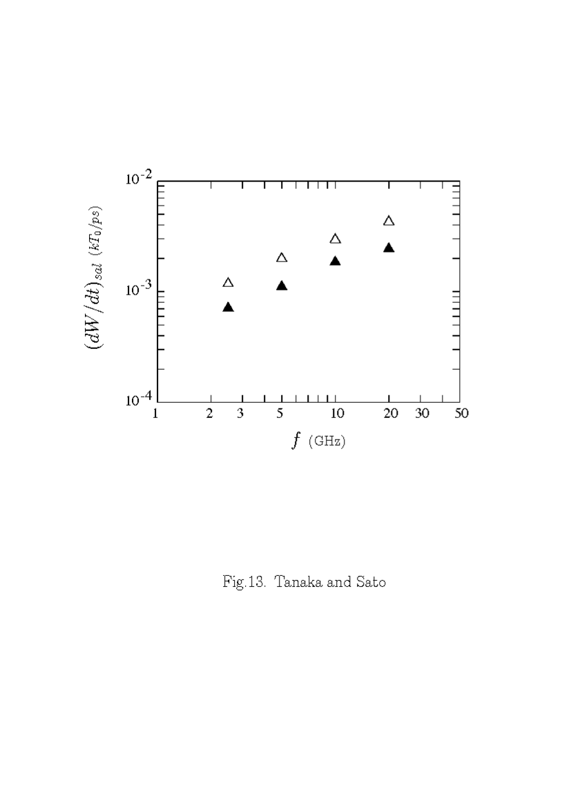
The dependence of the energy transfer rate from microwaves to salt water on the frequency of microwaves is shown in Fig.13. Both the energy transfer rate to the system (open triangles) and that to the kinetic energy of water (filled triangles) are scaled as
| (13) |
with , which is less sensitive to the microwave frequency than for pure water. We expect that the heating of salt water is not attributed to a simple acceleration of salt ions but is the result of the interactions between charged salt ions and the water network.
In order to verify the aforementioned statement, we prepare special saline solutions with (i) heavy salt ions, (ii) small Cl ions = 2.57Å, and (iii) non-charged salt, then apply the microwaves of 10GHz frequency and the strength V/cm. In the case (i), the salt ions are made ten times as heavy as their original masses, thus their vibrations are slower and smaller than the normal salt. The heating rate of water is found to be /ps, which is similar to that of the normal salt water shown in Table I. For the case (iii), the heating rate is small, /ps, and this is almost the same as that of the pure water. This reveals that a non-charged sphere, even if it is as large as the unit cell of the water network, does not actively interact with water molecules. An interesting case is the small salt ions of (ii), for which the heating rate is intermediate between those of the pure and salt waters, /ps. These special runs clearly indicate that large-size, charged ions like Cl- are playing important roles in the water heating process. Namely, large salt ions that do not fit in the unit cell of the water network make defects to it, and cleave the network through oscillations in response to the microwave electric field.
IV Summary
In this paper, we have studied the heating process of liquid water, ice and dilute saline solution by microwaves of 2.5-20GHz, where molecular dynamics simulations are performed with the explicit point-charge, rigid-body water model. We have verified that water in the liquid phase is heated via the rotational excitation of water electric dipoles, which is delayed from the microwave electric field. Microwave energy is transferred to both kinetic and inter-molecular energies of water, where the former corresponds to the heating of water and the latter is stored internally to rearrange water molecules. The latter energy occupies about one third of the total absorbed microwave power.
Hot water is significantly less heated than the water at room temperature, because the electric dipoles follow the microwave field with less phase-lags due to less friction. Water in ice phase is scarcely heated because the electric dipoles cannot rotate due to a tightly hydrogen-bonded network of water molecules. Dilute saline solution is substantially more rapidly heated than pure water. This is due to cleavage and weakening of hydrogen-bonded water network by large-size Cl- salt ions oscillating in the microwave electric field.
We remark that the microwave electric field in usual applications may be several orders of magnitude smaller than that used in the present study. The actual microwave field within the experimental sample should be considerably small compared with the surrounding vacuum space, because microwaves attenuate in the dielectric medium. If we assume that the strength of the microwave electric field is 10V/cm (700W microwaves correspond to the electric field 730V/cm, which becomes in water), and the wave frequency is 2.5GHz, then using the scalings Eqs.(11) and (12) we have
| (14) |
for the heating rate of water, where K. This corresponds to the temperature increase of roughly 70 degrees in two minutes, which is consistent with our daily experiences.
We have two other remarks: (i) For the microwave of small intensity, several orders of magnitude more wave periods are required to heat water and related materials. (ii) A part of the energy stored internally may be released as heat in a long time scale, but it is beyond the scope our present study. Finally, the energy associated with the electric dipole in the presence of microwaves in our simulation is not exceeding thermal energy or hydrogen-bond energy of water molecules. Therefore, except for secondary phenomena such as a long-time relaxation of water structures, our simulations are correctly reproducing the essence of the microwave heating process of water and saline solution.
Acknowledgements.
One of the authors (M.T.) thanks Prof.I.Ohmine and Dr.M.Matsumoto for fruitful discussions and providing him with the Ic ice generating program. This work was supported by Grant-in-Aid No.16032217 (2003-2005) and No.18070005 (2006-2010) from the Ministry of Education, Science and Culture of Japan. The present simulations were performed using our Linux-based PC cluster machines comprising of Pentium 4/EM64T and Opteron 275 processors.References
-
(1)
A.Stadler and C.O.Kappe,
J.Chem.Soc., Perkin Trans., 2, 1363 (2000);
G.Horais, S.Pichler,
A.Stadler, W.Gossler and C.O.Kappe, 5th Electronic Conference on Synthetic Organic
Chemistry (2001). -
(2)
G.Caliendo, F.Fiorino, E.Perissutti, B.Severino, S.Gessi,
E.Cattabriga, P.A.Borea
and V.Santagada, Euro.J.Med.Chem., 36, 873 (2001). - (3) R.D.Peelamedu, M.Fleming, D.K.Agrawal, and R.Roy, J.Am.Ceram.Soc., 85, 117 (2002).
-
(4)
A.R. von Hippel, ed., Dielectric Materials and
Applications, p.361 (MIT Press,
Cambridge, Mass., 1954). -
(5)
S.Havriliak, and S.J.Havriliak, Dielectric and Mechanical
Relaxation in Materials: Analysis,
Interpretation, and Application to Polymers (Hanser Publishers, 1997). - (6) U.Kaatze, V.Uhlendorf, Z.Phys.Chem. 126, 151 (1981); U.Kaatze, J.Chem.Eng.Data, 34, 371 (1989).
- (7) T.Yamaguchi, S.H.Chong, and F.Hirata, J.Chem.Phys., 116, 2502 (2002).
- (8) C.Vega, E.Sanz, and J.L.F.Abscal, J.Chem.Phys., 122, 114507 (2005).
- (9) N.J.English, and J.M.MacElroy, J.Chem.Phys., 118, 1589 (2003).
- (10) N.J.English, and J.M.MacElroy, J.Chem.Phys., 119, 11806 (2003).
- (11) N.J.English, Mol.Phys., 103, 1945 (2005); ibid., 104, 243 (2006).
- (12) Y.Rabin and M.Tanaka, Phys.Rev.Lett., 94, 148103 (2005).
- (13) H.Berendsen, J.Grigera, and T.Straatsma, J.Phys.Chem., 91, 6269 (1987).
- (14) H.C. Andersen, J.Comp.Phys., 52, 24 (1983).
- (15) M.Matsumoto, S.Saito, and I.Ohmine, Nature, 416, 409 (2002).
- (16) Initial configuration of ice is due to courtesy of Dr. M.Matsumoto.
- (17) P.P.Ewald, Ann.Physik, 64, 253 (1921).
- (18) J.W.Eastwood and R.W.Hockney, J.Comput.Phys., 16, 342 (1974).
- (19) M.Deserno and C.Holm, J.Chem.Phys., 109, 7678 (1998).
- (20) N.J.English, D.C.Sorescu, and J.M.MacElroy, J.Phys.Chem.Solids, 67, 1399 (2006).
- (21) N.J.English, and J.M.MacElroy, J.Chem.Phys., 120, 10247 (2004).
-
(22)
W.T.Coffey, Y.P.Kalmykov, and J.T.Waldron, The Langevin
Equation with Applications
in Physics, Chemistry and Electrical Engineering (World Scientific, 1996). - (23) I.Ohmine, J.Phys.Chem., 99, 6767 (1995).
- (24) C.Blanco, and S.M.Auerbach, J.Phys.Chem., 107, 2490 (2003).
- (25) H.Fukushima, Y.Yamanaka, M.Matsui, J.Japan Soc.Proc.Eng, 53, 743 (1987).
| state | temperature | heating rate | absorption rate | experiments |
|---|---|---|---|---|
| ice | 230K | very small | very small | 0.01 |
| water | 300K | 13 | ||
| watera | 400K | 2.4c | ||
| salt waterb | 300K | 18d, 42e |