present address: ]Dept. of Condensed Matter, Weizmann Institute of Science, 76100 Rehovot, Israel
Spin accumulation probed in multiterminal lateral all-metallic devices
Abstract
We study spin accumulation in an aluminium island, in which the injection of a spin current and the detection of the spin accumulation are done by means of four cobalt electrodes that connect to the island through transparent tunnel barriers. Although the four electrodes are designed as two electrode pairs of the same shape, they nonetheless all exhibit distinct switching fields. As a result the device can have several different magnetic configurations. From the measurements of the amplitude of the spin accumulation, we can identify these configurations, and using the diffusion equation for the spin imbalance, we extract the spin relaxation length nm and an interface spin current polarization at low temperature and nm, at room temperature.
pacs:
72.25.Ba, 72.25.Hg, 73.23.-b, 85.75.-dIt is an interesting question what happens to the transport properties in non-magnetic conductors if the carriers are spin polarized. This is both a fundamental question in the field of spintronics and has also practical applications rew . In an all-electrical setup, spin polarized carriers are injected by driving a current from a ferromagnet. This induces an imbalance between the two spin populations, that, for diffusive systems, extends over a distance of order from the interface. is the spin lifetime and the electron diffusion constant for the conductor. If a second ferromagnet is present within from the injector, it can be used to detect the spin accumulation.
In order to study spin related transport in a non-magnetic metal using a lateral device, a true multi-terminal device is needed. By spatially separating the current path from the voltage probes, one can distinguish between truly spin-related effects and spurious, interface-dependent phenomena.
This technique, pioneered by Johnson and Silsbee (1985), has been successfully extended to the study of spin transport in diverse systems, from metallic systems at low and room temperature (Jedema et al., 2001; jed, ; Urech et al., 2004; Kimura et al., 2004; Garzon et al., 2005) to carbon nanotubes (Tombros et al., 2005), and to a lesser extent, in semiconductors (Ohno et al., 1999), superconductors (Beckmann et al., 2004) and organic materials (Dediu et al., 2002). In the case of metallic systems, the interface between the ferromagnet and the metal has been varied from transparent to tunnelling. Valenzuela et al. (2005) have used a lateral spin valve device to probe the magnitude and sign of the polarization of a ferromagnetic contact as a function of the injecting bias voltage.
Recently, the spin accumulation in a diffusive Al island, with all lateral dimensions smaller than has been studied (Zaffalon and van Wees, 2003). The island is contacted by four Co electrodes via tunnel barriers for injection/detection of the spin accumulation. However, this system suffers from several drawbacks such as difficulty of fabrication and, more importantly, large magnetic fringing fields at the end of the electrodes, which can affect the spin accumulation. Also it is not straightforward to reduce the island’s volume to increase the spin accumulation.
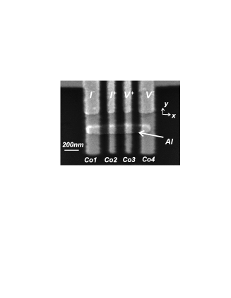
In this work, we focus on a 1-D system (only one lateral dimension larger than ) in which an Al island is contacted with four in-line Co electrodes, as shown in Fig. 1.
The orientation of the electrodes’ magnetization is pinned along the electrode axis in the substrate plane by the shape anisotropy and can be switched by an external magnetic field in the -direction. The inner/outer electrode pairs are designed to have different widths.
As the switching field is lower for the wider (outer) electrodes, we have a control on the magnetization of the individual electrodes. However, we will see that the switching fields for identically designed Co electrodes may not be the same. This is due to the small differences produced during the fabrication and to magnetic interactions between the electrodes ends.
Here, we study the spin accumulation as a result of the different orientations of the four Co electrodes and we show how, from the magnitude of the spin accumulation, we can infer the magnetic configuration of the electrodes, as well as the polarization of the Co/Al2O3/Al contacts and the spin diffusion length in Al.
The theoretical analysis of the spin imbalance in our Al strip is based on the model for diffusive transport introduced by van Son et al. (1987); Johnson and Silsbee (1988) and refined by Valet and Fert (1993): there transport was analyzed for transparent ferromagnetic/non-magnetic (FM/N) interfaces. It was later understood (fil, ) that the efficiency of the injection, i.e. the ratio spin polarized current to total current, can be increased by interposing a spin dependent interface between FM and N, such as a high resistance tunnel barrier.
The devices (see Fig. 1) are made by electron beam lithography and two-angle shadow mask evaporation process. The shadow mask consists of a PMMA-MA/germanium/PMMA try-layer, the base resist having higher sensitivities than the top resist as to enable, by selective exposure, the making of a suspended mask with large undercuts. First, we deposit through the suspended mask 20 nm thick Al at 35∘ on the Si/SiO2 substrate using electron-gun evaporation to form 1 m nm strip. Next, we expose Al to pure oxygen at a pressure of mbar for few minutes to form a thin Al2O3 layer. In the last step, four Co electrodes 30 nm thick are deposited perpendicular to contact the Al strip, without breaking the vacuum. The resistance of the Al/Al2O3/Co tunnel junctions ranges from m2, depending on the oxidation time.
As mentioned above, the inner/outer Co electrodes have been designed to have different widths, with the outer contacts at 150 nm and the inner ones at 80 nm. This allows us to independently flip the magnetization direction of the electrodes, when an external magnetic field is slowly swept ( 1–2 mT/sec), along the contacts’ direction. Nevertheless, we will present measurements in which sometimes the narrow contacts switch at lower fields than the wider ones.
Measurements were performed at about 2 K and at room temperature by standard a.c. lock-in techniques, with a modulation frequency of 7–17 Hz. We have measured 5 devices in detail.

All measurements presented here are taken in the non local measuring configuration: a current is injected from Co2 to Co1 and a voltage is detected between Co3 and Co4. Since no charge current flows through the voltage detectors, our device is not sensitive to interface or bulk magnetoresistance related effects, but only to the spin degree of freedom.
Figure 2 shows two typical nonlocal spin valve measurements for different devices at low temperature. The plotted signal is , as a function of the in-plane (in the direction) magnetic field. Referring to Figure 2(a) device A, at +200 mT, all contacts’ magnetization are aligned parallel to the external magnetic field, in the direction. We sweep the magnetic field toward negative values. At –80 mT, the two larger electrodes, namely Co1 and Co4, flip their magnetization (antiparallel configuration), and the detected signal increase to 90 m above a zero background. Upon increasing the magnetic field further to –120mT, the two smaller electrodes, Co2 and Co3, flip, the magnetization of the four contacts is parallel again, but now in the opposite direction (). The reverse trace show a similar behavior. Also for repeated sweeps, the field at which the magnetization switching occurs is within 20 mT of the given values.
Now, what happen if all four Co electrodes switch their magnetization at different fields? Figure 2(b) shows such a measurement for device B. We interpret the additional steps in the signal as the fingerprint of different magnetic configurations of the electrodes. Again, at –170 mT, we start with a parallel configuration of the Co electrodes and with a background level of +70 m (the nature of which is unknown). Ramping the field to positive values, at +75 mT, Co1 flips, the injectors are antiparallel and the signal increase above the background level by +17 m. At +90 mT the other largest electrode, Co4, reverses, so that also the detectors are antiparallel to each other. The spin signal increases now by +90 m above the background level. At 106 mT, Co3 strip flips, the detectors return to parallel and the signal drops by 20 m below the background level. The electrodes stay in this configuration until reaching a field of +120 mT, when the other smallest electrode, Co2, switches and the signal reaches the background level. The sweep to negative fields shows a similar behavior, with a difference in the value of the spin signal, probably due to presence of the magnetic domains in the Co strips.
It is worth mentioning at this point that, given the symmetric positions of the electrodes on the island, one cannot tell whether the electrode flipping at the lowest field, for example in Fig. 2(b), is Co1 or Co4. This uncertainty could have been avoided, for instance if the electrodes were arranged in a wide, narrow, wide, narrow fashion (and if the switching field is determined by the lateral dimension of the electrode only).
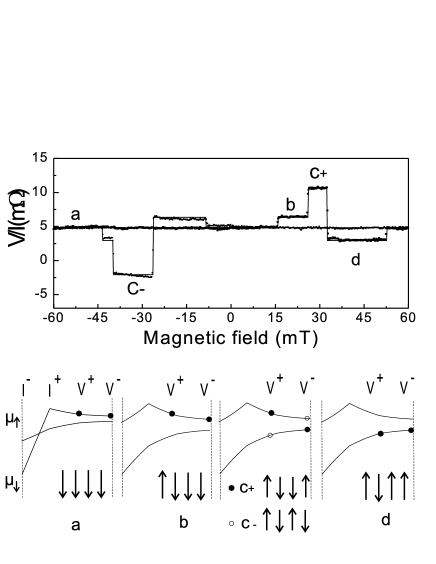
Figure 3 top panel shows data for device C measured at room temperature. The behavior is similar to that of device B. The spin signal of 6-7 m is smaller due to a lower spin relaxation length, and a somewhat smaller interface polarization at room temperature. For both positive and negative sweep directions of the magnetic field, we identify five magnetic configurations, a, b, c+, c– and d.
To clearly illustrate the spin contributions in different magnetic configurations, we refer to Fig. 3 (bottom). Here we show schematically the spatial dependence of the spin-up () and spin-down () chemical potentials in the Al island, for the different magnetic configurations, when a charge current is injected from to . and represent the position of the voltage probes. Let us assume, for the moment, the contacts to be 100% spin polarized: would detect either or , according to the magnetization direction of the contact.
In the configuration a in which all contacts are parallel, and the spin related signal arises from the spatial dependence of .
When Co1 flips, configuration b, the injectors are antiparallel, a non-uniform spin accumulation is present in the Al island, and relaxes from the points of injection, giving rise to a spin current . Note that the charge current at Co3 and Co4 is absent. Although the detectors are still parallel and sensitive only to spin down channel, the signal is somewhat larger than in configuration (a), as it can be seen in the measurement, by 1.6 m.
When Co4 reverses, configuration c+ (black dots), also the detectors are antiparallel, the electrode detects and , . In this configuration, with both injectors and detectors antiparallel to each other, we obtain the highest spin contribution, that is 6 m in our measurement. When also Co3 flips, configuration d, the detectors now measure the spatial dependence of , so that the magnitude of the signal is the same as in configuration b but with opposite sign. In the reverse trace, configuration c– (open dots) the notable difference is that Co3 flips before Co4 and the signal changes sign as is sensitive to spin up while injects spin down electrons.
To evaluate qualitatively the experimental results, we model the system as i) one dimensional and we assume injectors and detectors to be ii) collinear (parallel or antiparallel to ), and iii) point-like. Assumption i) and iii) are justified by the fact that previous measurements reported nm at RT, (jed, ; Zaffalon and van Wees, 2003), larger than the island’s and contacts’ width, and ii) because shape anisotropy keeps the magnetization in-plane and in the direction of the contact. The contacts’ positions of Co1, Co2, Co3, Co4 electrodes to the Al island are at , , and , with . A charge current is injected at and extracted at . As the injectors are ferromagnetic, the injected charge current is partially spin polarized, , ( and ). This produces a space dependent spin accumulation in the Al island (the minus sign because of the opposite directions of the charge current) where . The spatial dependence of in Al strip, can be calculated by solving the 1-D spin coupled diffusion equation (van Son et al., 1987) with the boundary conditions at either ends of the island or , that is, no charge or spin current at . The solution is (Zaffalon, 2006)
| (1) |
where and A are the conductivity and sectional area of the Al strip and and are given by
| (2) |
In the limit , one recovers the 1-D equation (jed, ) and in the limit , one finds the 0-D expression (Zaffalon and van Wees, 2003). The ferromagnetic detectors positioned at and have polarization and . We measure the difference of the detectors’ potentials at this points, , and the spin dependent resistance is .
In the fitting, the free parameters are and , the position of the electrodes are as determined from the SEM micrographs. Also, a constant background is added to the calculated signal. We find at low temperature a spin diffusion length nm and an interface polarization and nm, at room temperature. Both these values are slightly smaller than previously found jed ; Valenzuela et al. (2005); Zaffalon and van Wees (2003).
Figure 4 shows a non-local spin valve measurement at room temperature for device D. We observe, while sweeping at positive fields, at around +14 mT, an extra step in the signal and we interpret this as Co4 flipping its magnetization through an intermediate step. We also note in the reverse trace that Co3 reverses before Co4. Also here, the fit follows well the experimental data: this implies that all junctions have the same polarization.
In summary, we have studied spin accumulation in an Al island, connected by four Co electrodes through low resistance junctions. From the measurements of the amplitude of the spin accumulation we can identify the sequence of the magnetization switching of the ferromagnetic contacts. The analysis based on eq. (1) allows us to extract and .

This work was supported by the Stichting Fundamenteel Onderzoek der Materie (FOM) and MSC. We acknowledge useful discussions with Andrei Filip and Steven M. Watts and the technical support of Gert ten Brink and Pim van den Dool.
References
- (1) For recent reviews, see: D. D. Awschalom, D. Loss and N. Samarth, Semiconductor Spintronics and Quantum Computation (Springer-Verlag, 2002); I. Žutić, J. Fabian and S. Das Sarma, Rev. Mod. Phys., 76, 3231 (2004).
- Johnson and Silsbee (1985) M. Johnson and R. H. Silsbee, Phys. Rev. Lett. 55, 1790 (1985).
- Jedema et al. (2001) F. J. Jedema, A. T. Filip, and B. J. van Wees, Nature 410, 345 (2001).
- (4) F. J. Jedema, H. B. Heersche, A. T. Filip, J. J. A. Baselmans, B. J. van Wees, Nature 416, 713 (2002); F. J. Jedema, M. V. Costache, H. B. Heersche, J. J. A. Baselmans and B. J. van Wees, Appl. Phys. Lett. 81, 5116 (2002).
- Urech et al. (2004) M. Urech, J. Johansson, V. Korenivski, and D. B. Haviland, J. Magn. Magn. Mater. 272, E1469 (2004).
- Kimura et al. (2004) T. Kimura, J. Hamrle, Y. Otani, K. Tsukagoshi, and Y. Aoyagi, Appl. Phys. Lett. 85, 3501 (2004).
- Garzon et al. (2005) S. Garzon, I. Žutić, and R. A. Webb, Phys. Rev. Lett. 94, 176601 (2005).
- Tombros et al. (2005) N. Tombros, S. van der Molen, and B. van Wees, cond-mat/0506538 (2005).
- Ohno et al. (1999) Y. Ohno, D. K. Young, B. Beschoten, F. Matsukura, H. Ohno, and D. D. Awschalom, Nature 402, 790 (1999).
- Beckmann et al. (2004) D. Beckmann, H. B. Weber, and H. v. Löhneysen, Phys. Rev. Lett. 93, 197003 (2004).
- Dediu et al. (2002) V. Dediu, M. Murgia, F. C. Matacotta, C. Taliani, and S. Barbanera, Solid State Commun. 122, 181 (2002).
- Valenzuela et al. (2005) S. O. Valenzuela, D. J. Monsma, C. M. Marcus, V. Narayanamurti, and M. Tinkham, Phys. Rev. Lett. 94, 196601 (2005).
- Zaffalon and van Wees (2003) M. Zaffalon and B. J. van Wees, Phys. Rev. Lett. 91, 186601 (2003).
- van Son et al. (1987) P. C. van Son, H. van Kempen, and P. Wyder, Phys. Rev. Lett. 58, 2271 (1987).
- Johnson and Silsbee (1988) M. Johnson and R. H. Silsbee, Phys. Rev. B 37, 5326 (1988).
- Valet and Fert (1993) T. Valet and A. Fert, Phys. Rev. B 48, 7099 (1993).
- (17) A.T. Filip, B.H. Hoving, F.J. Jedema, B.J. van Wees, B. Dutta and S. Borghs, Phys. Rev. B 62, 9996 (2000); G. Schmidt, D. Ferrand, L.W. Molenkamp, A.T. Filip and B.J. van Wees, Phys. Rev. B 62, R4790 (2000); E.I.Rashba, Phys. Rev. B 62, 16267 (2000).
- Zaffalon (2006) M. Zaffalon, Ph.D. thesis, University of Groningen (2006).