Random particle packing with large particle size variations using reduced-dimension algorithms
Abstract
We present a reduced-dimension, ballistic deposition, Monte Carlo particle packing algorithm and discuss its application to the analysis of the microstructure of hard-sphere systems with broad particle size distributions. We extend our earlier approach (the “central string” algorithm) to a reduced-dimension, quasi-3D approach. Our results for monomodal hard-sphere packs exhibit a calculated packing fraction that is slightly less than the generally accepted value for a maximally random jammed state. The pair distribution functions obtained from simulations of composite structures with large particle size differences demonstrate that the algorithm provides information heretofore not attainable with existing simulation methods, and yields detailed understanding of the microstructure of these composite systems.
I Introduction
Hard-sphere particle packing models have proven useful in the study of liquids and fluids Bernal (1959, 1960); Scott and Kilgour (1969); Martys et al. (1994), glasses Truskett et al. (2000); Kim and Munakata (2003), foams O’Hern et al. (2001), granular flows Kadanoff (1999); Makse and Kurchan (2002), and amorphous solids Bennett (1972); Srolovitz et al. (1981), and have been extended to non-spherical particles as well Coelho et al. (1997); Donev et al. (2004a). Perhaps the most interesting application of particle packing is its use as a tool to understand the microstructure of particulate materials and powders. Understanding order in particulate systems is an outstanding question, and particle packing approaches have contributed to this line of research for some time Bernal (1959, 1960); Bennett (1972); Berryman (1983); Jullien et al. (1996); Quintanilla and Torquato (1996); Rintoul and Torquato (1996a, b); Kansal et al. (2000); Truskett et al. (2000); Torquato and Stillinger (2001); Kansal et al. (2002). Many researchers also use the tool to study a variety of related lines of research, including the interpretation of amorphicity as spatial chaos in one dimension Reichert and Schilling (1984), pressure and entropy in crystals Speedy (1998), thermodynamics of slowly sheared granular systems Makse and Kurchan (2002), the onset of dilatancy in loose packings Onoda and Liniger (1990), transport properties Truskett et al. (2000), and porosity Yang et al. (1996, 2000); Truskett et al. (2000) to name a few. Of particular interest is the recent work on the concept of random close packing and the more rigorous definition of jamming in these systems Torquato et al. (2000); Kansal et al. (2002); O’Hern et al. (2003); Donev et al. (2004b).
Particle packing simulations take a variety of forms. Early attempts incorporated real particles such as powders McGeary (1961), ball bearings Scott and Kilgour (1964, 1969); Finney (1970), balls and spokes Bernal (1959, 1960), and recently glass beads in a neutrally buoyant fluid Onoda and Liniger (1990), horizontally shaken beads Pouliquen et al. (1997), and M&M111M&M’s Candies is a registered trademark of Mars, Inc. chocolate candies Donev et al. (2004a). Numerical and Monte Carlo techniques include seed aggregation Bennett (1972) or variants thereof Matheson (1974), growth in a unidirectional force field Visscher and Bolsterli (1972), shrinking of randomly placed spheres Jodrey and Tory (1985), dynamic, growing spheres on the surface of a hypersphere Tobochnik and Chapin (1988), overlap relaxation followed by space expansion and vibration He et al. (1999), conjugate gradient energy minimization O’Hern et al. (2002, 2003), and various forms of molecular dynamics Lubachevsky and Stillinger (1990); Lubachevsky et al. (1991); Elliot and Windle (2000); Kim and Munakata (2003).
II Motivation for this work
We seek to calculate the bulk and microstructural properties of particulate systems composed of rigid or semi-rigid particles embedded in an elastic or viscoelastic matrix Davis et al. (1993); Davis (1999). This area of research demonstrates that the macroscopic properties of a composite material (e.g., the modulus) can depend on the microscopic details of the packing structure comprising the material Hubner et al. (1999); Hatch . For example, the bulk response of a particulate system to an applied external stress can be determined in large part by particles in the pack that lie very near each other (i.e., within a fraction of a particle radius). For this reason, our desire to calculate bulk properties using a first-principles approach relies on a thorough understanding of the material microstructure. Moreover, detailed knowledge of the microstructure of such systems allows for related studies, such as combustion of solid rocket propellants Kochevets et al. (2001).
For some systems of interest, the particulate ingredients that comprise the system may include particles with potentially very large size differences. Packing simulation of such systems with traditional methods can be problematic as the size difference increases. For example, a simulation of spherical particles with a size ratio of 100:1 would require small spheres for each large sphere in the pack (assuming an equal mass ratio). Obtaining good statistics for such packs would require literally billions of particles in the pack, which is clearly unattainable with extant computational methods.
In an earlier paper, one of us introduced the concept of the central string algorithm Davis and Carter (1990). The key feature of that approach is the idea that some packing statistics near a line drawn through a composite structure ought to mimic the three-dimensional statistics of the pack for a sufficiently long line. We emphasize that a reduced-dimension algorithm may not be able to supplant a 3D algorithm for all statistics of interest. In this paper, we focus on particle packing fraction and radial distribution functions; the treatment of other statistics is under investigation.
The appeal of the reduced-dimension approach is that, when correctly implemented, it should allow researchers to calculate certain statistics for packs with large particle size variations which would otherwise be unattainable due to the long computation times associated with a full three-dimensional packing of such composite materials.
The earlier work Davis and Carter (1990) demonstrated the promise of a reduced-dimension approach, but the central-string method exhibited shortcomings. The most serious shortcoming present in the previous model was that the perturbation approach was unable to prevent particle segregation during growth. Also, the earlier model was unable to provide detailed information about the microstructure because of the limited structure found around the central string. The present work seeks to overcome these shortcomings by extending the central-string approach to a quasi-3D method, thereby providing the ability to calculate detailed microstructure, including radial distribution functions and coordination numbers.
Our algorithm follows most closely that of Visscher and Bolsterli Visscher and Bolsterli (1972), and is in essence a ballistic dispersion, reduced-dimension Monte Carlo simulation.
III The concentric-cylinder, reduced-dimension approach
A natural extension of the central-string approach to reduced-dimension particle packing is to extend the central string into a cylinder, producing a quasi-3D packing algorithm. In effect, we extend the notion of a line drawn through the three-dimensional particle pack to a cylinder drawn through the particle pack. Whereas the particles that intersected the line represented the packing statistics (for a sufficiently long line), a cylinder of equivalent length which cuts through the pack should also represent the pack statistics, but with more accuracy (per unit length) because more particles are included in the cylinder than intersect the line. In particular, if properly simulated and interpreted, this approach should provide sufficient information to allow a detailed examination of the pack microstructure.
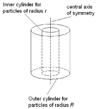
The key to this reduced-dimension approach is to represent each particle of a different size or density (a mode) in the pack by its own cylinder, scaled appropriately to the particle’s size. We define a particle mode to be all particles in a pack that are indistinguishable relative to one or more properties of interest. A monomodal pack comprises a single cylinder (and is in fact equivalent to a three-dimensional pack). A binary pack includes two concentric cylinders, whose radii are scaled proportionally to the size of each particle. A ternary pack comprises three cylinders, and so on; see Fig. 1. All cylinders share a common axis, but the cylinder radii depend on each particle’s size.
We construct the pack by dropping particles at a randomly chosen position within each particle’s cylinder. When simulating more than one particle mode, the order in which the particles are dropped is also random (respecting the final number of each particle mode required to represent the desired mass fraction of each mode). Each particle is dropped above the pack and allowed to descend into the pack under the influence of a unidirectional force field (e.g., gravity) acting along the -axis until the particle finds a contact stability point. Until the particle finds a stability point, it will roll along other particles or the roll corridor defined by one or more particles and/or the cylinder wall. Contact stability refers to whether the current sphere is in compressive contact with an object or in tensile contact. If it is in compressive contact with another sphere or the cylinder wall, the particles push against each other due to the current sphere’s weight. When a particle touches three or more objects compressively, it is stable and is placed at that position. When in tensile contact with another particle or the cylinder wall, the current sphere will roll away from the object unless it already has three or more compressive contacts. After the particle is placed at a contact stability point, another particle is dropped and the sequence repeated until completion (all particles dropped and stable).
The dropping and rolling of pack particles does not include any dynamics. The particles do not bounce, do not gain speed or shoot off the edge of another particles with a parabolic trajectory. Once placed at a stability point, the particle remains there for the duration of the simulation. It is as if the particles are being dropped in a highly viscous fluid so that all inertia is absent and the particle creeps to its final resting place. In general, we use a number of trial drops (8-32) for each particle and choose the lowest of the set to ensure the densest packing behavior.
As we build the pack, each particle mode remains within its own cylinder. The smallest mode particle resides in the smallest cylinder, and is closest to the axis of symmetry. Larger particles may lie within the inner cylinders, but also extend into outer cylinders; each mode is always constrained to remain within its own cylinder. The largest particle in the pack may lodge in any of the cylinders, and in the outermost cylinder it resides alone. It should be clear that setting all cylinders to be the same size (the size of the largest particle’s cylinder) produces a three-dimensional simulation. The implementation we have chosen thus allows us to build simulated packs with both reduced- and three-dimensional approaches by simply choosing each particle’s cylinder size appropriately.
III.1 The power of the reduced dimension approach
The development of the reduced-dimension approach to particle packing provides the opportunity to analyze particle packs with broad size distributions which would otherwise be computationally prohibitive. A full, three-dimensional simulation of 600,000 particles in a ternary pack with size ratios of 30:50:175 consumes 40 hours (real-time) on a fast desktop PC, placing approximately four particles per second. A reduced-dimension simulation which produces comparable statistical results runs in two minutes, placing 170 particles per second. This computational advantage increases tremendously as the particle size ratio increases. We recently investigated a composite material consisting of four particles of varying sizes with a maximum size ratio of 77:1; the reduced-dimension simulation modeled particles and required about 100 hours to complete. We estimate that a three-dimensional simulation of the same fidelity would have required about particles and about 100 years computer time with our simulation.
In general, we find that for equal numbers of particles, the algorithm’s time to completion as a function of the the particle size ratio varies as for a fully three-dimensional simulation, but only as using the reduced dimension algorithms. Using the reduced-dimension approach, the algorithm time to completion as a function of the number of particles is linear in , with a particle size ratio of about 7-10:1. In three dimensions, the same calculation varies as . The reduced-dimension algorithm brings the simulation of complex particle packs with large particle size variation into the realm of possibility.
IV Implementation of the concentric cylinders algorithm
The introduction of concentric cylinders of arbitrary size into the basic ballistic deposition algorithm introduces challenging analytical and simulation issues. The inclusion of the arbitrary-size cylinders must not be allowed to change the microstructure and must not introduce artificial structures into the simulation.
IV.1 Particle segregation
The primary problem introduced by the concentric-cylinder, reduced-dimension algorithm is particle segregation during pack growth. Particle segregation takes one of two forms: segregation in the growth direction (axial segregation), and segregation in the radial direction (normal to the growth direction). Segregation in the growth direction may occur for any particle in the simulation, while segregation in the radial direction may occur for all but the smallest particle in the simulation.
IV.1.1 Axial segregation
Segregation in the growth direction for small particles is a “real” phenomenon for particle packing in a unidirectional force field. In essence, the small particles fall through the interstitial spaces between bigger particles until they find a resting place. The final resting position can be far below the current pack “surface” if the pack is porous (as compared to the small particle’s radius). This effect is an artifact of the simulation method, and doesn’t represent real composite materials that are prepared through adequate mixing or in the presence of an interstitial matrix or binder.
To prevent axial segregation of small particles, we introduce the concept of the catch net. The catch net prevents particles from falling too far (typically a few radii) below the growing pack surface, even if there is an allowed pathway. The catch net position after the addition of the -th particle, is:
| (1) |
where is the height (position in the growth direction) of the -th particle, is the radius of the particle (of mode ), is a uniform random deviate on the range (0,1), is the length of the moving average, as given by
| (2) |
with equal to the radius of the confining cylinder of the smallest mode, and is the exponential moving average of length of the time-series variable :
| (3) |
where
| (4) |
In the current implementation, the default value chosen for is the number of particles required to “tile” the innermost cylinder, as given by Eq. (2). Particles that would otherwise fall below the catch net surface are prevented from doing so, are fixed at the current position of the catch net, and remain at that position during the remaining pack growth. The catch net surface only acts on particles with the smallest radius in the innermost cylinder.
Particles larger than the smallest particle may also experience segregation in the growth direction. The segregation of these particles is a direct artifact of the reduced-dimension algorithm. When the larger particles fall in an outer cylinder, they do not have smaller particles to support them, so they fall until they lodge against other large particles. If the large particles are densely populated in the pack, segregation is not an issue, as they will support each other at the appropriate position. If the large particles are sparsely populated in the pack, a new particle may fall many diameters below what would otherwise be the pack surface. This undesired effect is a direct consequence of the fact that the reduced-dimension algorithm does not include all particle types in the cylinders outside the innermost cylinder.
To remedy the segregation of these particles in the growth direction, we introduce the concept of a synthetic surface. The synthetic surface serves to support particles that would otherwise fall below the surface defined by the particles in the innermost cylinder. The definition of the synthetic surface position, , after the addition of the -th particle is:
| (5) |
where is the height of the -th particle, is the radius of the -th particle, and is the number of spheres included in the average. It is important to point out that the sum is over the particles with the highest north poles in the pack, not the last particles added. (The “north pole” is the position of the top of the sphere–the center of the sphere plus the sphere radius.) Any particle whose center would fall below the synthetic surface position is prevented from doing so, fixed at the current position of the synthetic surface, and remains at that position during the remaining pack growth. The synthetic surface is a single surface active for all particles in the pack except the particles in the innermost cylinder (which is managed by the catch net). In the current implementation, = , as given by Eq. (2).
IV.1.2 Radial segregation
Particle segregation in the radial direction is also an artifact of the reduced-dimension approach. The effect is most pronounced for particles whose radius is significantly larger than the radius of an inner cylinder. These particles tend to roll off the pedestal formed by particles in the inner cylinder, because uneven variations in the surface structure act as inclined planes. If the particle radius is sufficiently large, the moment arm above these planes is big enough to cause the particle to roll out of the inner cylinders. A straightforward calculation of the geometry of the situation shows that rolling can occur for particle radii ratios as small as a few to one.
To remedy this situation, we force particles to remain within the largest cylinder that encloses the particle’s center position upon selection of its drop point. Choosing drop points to be uniformly randomly distributed across all allowed cylinders ensures that each cylinder contains the correct number of particles, accurately representing a three-dimensional pack. Examination of the radial distribution of each particle mode in the resulting pack shows that this approach accurately maintains the expected dependence of the particle distribution.
IV.2 Edge effects
Another potential problem that can be important but is easily negated is an edge effect, which occurs when the radius of the confining cylinders is not large compared to the particle radius. If the confining cylinders for each particle mode are chosen to be not much bigger than the particle radius (e.g., just a few times larger than the particle radius), then edge effects tend to dominate the particle statistics near the cylinder walls. This undesired effect can be substantial: for some configurations, these edge effects reduce the population of particles near the cylinder walls by as much as 50 percent from the nominal values; the particles are no longer distributed as . Fortunately, this effect has a simple remedy; we set the confining cylinder for each particle to be at least 20 times the particle radius . Tests show that this reduces the magnitude of the variation from the nominal value in particle population at the edges to less than one percent. This causes the simulation to run slower than it would with a smaller cylinder, but is required in order to ensure pack integrity.
IV.3 Implementation summary
In summary, we introduce a reduced-dimension approach to the standard ballistic deposition method. Concentric cylinders contain particles of various sizes, with increasing cylinder diameter corresponding to increasing particle size. The particles are distributed as within each cylinder, out to each particle’s outermost constraining cylinder. The presence of small particles is simulated in the outermost cylinders (where they do not reside) by calculating the effective surface height of these particles and representing that surface throughout all larger cylinders. We prevent small particles from percolating downward through large interstitial voids in the pack. We consider the algorithm to be “quasi-3D” because each cylinder is at least 20 times the radius of the particle it confines.
Detailed analysis of the simulation results, including the resulting pack structure, demonstrates conclusively that the reduced-dimension approach produces numerically identical results (within statistical uncertainty) to three-dimensional simulations, but at much less cost. In some cases, the reduced-dimension algorithm allows calculation of microstructure for packs that would otherwise be unattainable with existing methods.
Each of the results presented in this paper has been verified by direct comparison to three-dimensional simulations which do not include any of the reduced-dimension algorithms. In the discussion to follow, we present comparison results between reduced-dimension and 3D simulations that verify this claim.
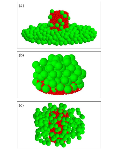
In figure 2, we show representations of particle packs obtained from the simulations. Inset (a) shows the effects of axial segregation of large particles when the synthetic surface is not implemented. Inset (b) shows the effects of axial segregation of small particles when the catch net is not implemented. Inset (c) shows a reduced-dimension pack with all reduced-dimension algorithms implemented.
IV.4 Limits of the reduced-dimension algorithm
We haven’t performed an exhaustive comparison of results obtained from 3D and reduced-dimension simulations due to the very long run-times associated with 3D simulations of particle packs with very large (e.g., 10:1) particle size differences. We have determined limits on some simulation parameters such as cylinder size, total particle number, and largest-smallest size ratio. As described above, to avoid edge effects, each cylinder size must be at least 20 times the particle radius; smaller cylinders yield unacceptable deviations from uniformity in particle density across the cylinder. To acquire acceptable statistics, each particle mode should occur at least times in the pack. This operational limit leads to constraints on the largest-smallest particle size ratio that can be examined with the current algorithm, and depends on the computing resources available. Currently, total particle numbers in the pack should be constrained to less than about particles, meaning that particle size ratios of about 1000:1 are attainable for binary packs, depending on the relative mass fraction in each mode. We have successfully simulated particle packs with about particles, consisting of about 30 particle modes, with the largest particle radius ratio around 80:1.
V Calculation of pack microstructure and statistics
The concentric cylinders approach introduces complexity into the calculation of pack microstructure and packing statistics. The reduced-dimension nature of the pack destroys the three-dimensional symmetry of the pack; the pack is highly anisotropic. The calculation of packing fraction and radial distribution functions is complicated by this structure. We cannot directly calculate microstructural statistical properties in the usual way for a 3D pack.
Fortunately, this complication is fairly easy to overcome by correctly accounting for the asymmetry. Some properties require that we include only the innermost cylinder’s structure in our calculations, while others require us to renormalize the statistic to account for the anisotropy in the reduced-dimension pack.
The calculation of volume (packing) fraction is done for only the innermost cylinder. Each particle’s contribution to the packing fraction simply becomes the ratio of the volume each particle occupies in the innermost cylinder to the total volume of that cylinder. (Only the portion of the particle that lies within the innermost cylinder is included in the volume calculation.)
The calculation of the radial distribution function requires an accounting of the pack asymmetry. The radial distribution function is defined to be the number density of particles of type that are within the range ring and from particles of type :
| (6) |
where is the range from particle to particle , and is the number of particles at the given range Cusack (1987); Mason (1968).
To calculate the radial distribution function for a reduced-dimension pack, we calculate according to equation (6) within cylinder , and renormalize the resulting value by multiplying the total volume of the range ring within cylinder by the appropriate value to obtain a full steradians at the given range. In essence, the contribution to within cylinder is weighted according to the fraction of contained within cylinder .
We show below that detailed comparisons of three-dimensional results obtained without any reduced-dimension algorithms to this calculational approach for the reduced-dimension algorithm confirm the validity of this approach.
VI Applications
VI.1 Comparison to mechanical packing experiments
We have used this new reduced-dimension algorithm extensively in the analysis of monomodal and multimodal packs. This allows us to compare the simulation results with previously published experimental and simulation data. It’s not entirely clear what would be the best basis for comparison. Mechanical shaking experiments such as those performed by McGearyMcGeary (1961) appear to be the most applicable experimental work. However, there is known variation in the results of such experiments; Scott showed that, depending on the physical methods used, the packing fraction of equal-sized spheres could vary between 0.60-0.637Scott (1960).
A similar, but more dramatic, variation exists in numerical and simulation methods. In crystalline structures, the simple cubic structure has a packing fraction of about 0.52, while the close-packed face-centered cubic lattice and its stacking variants has a packing fraction of about 0.74. So-called random-close packed structures generally fall in between these limits, but the very definition of a random close-packed structure is in questionTorquato et al. (2000).
In general, as one would expect, the ballistic deposition approach used here yields packing fractions that are lower than those obtained by other methods. For example, the measured monomodal packing fraction in our simulation is 0.60, about three-four percent less than that expected for a maximally random jammed pack of equal size hard spheres Kansal et al. (2002).
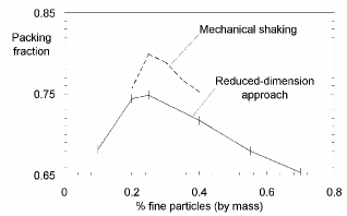
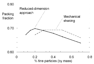
We have compared the packing fractions obtained from our simulation with those of previously published mechanical shaking experiments, and find a similar lower value than published measurements for binary mixtures McGeary (1961). In Fig. 3, we show a comparison of the packing fractions obtained from McGeary (1961) and our simulation for a binary pack with size ratio of 124:19 (about 6.5). The data shows close agreement between the packing fractions at small and large mass ratios, but more deviation for mass fractions that are approximately equal. However, the qualitative agreement between the curves is excellent, with the maximum value of the packing fraction occurring at the same mass fraction value (25% fine).
Investigations with binary packs of various size ratios show that the difference between the measured packing fraction and that produced by our simulation can be as large as several percent in some cases (for large particle size differences); see Fig. 4. We suspect that the large difference arises primarily because of the ballistic deposition method employed. The ballistic deposition approach inevitably will produce lower packing fractions than would be obtained with mechanical shaking, where the particles may reorient themselves cooperatively as a group.
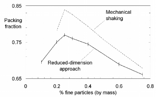
Similar comparisons of the simulation to published data for smaller size ratios yields a somewhat surprising result. We find a closer quantitative agreement for a size ratio of 31:9 (about 3.4), but the packing fraction peak occurs at a different value of the mass fraction for our simulation than that published in McGeary (1961). Fig. 5 shows a fairly broad peak near a mass fraction of about 40 percent fine particles for the mechanical data, but our simulation packing fractions are largest near a mass fraction of 20 percent fine particles. We point out that this trend in peak position is consistent with simulations at other particle size ratios. We cannot determine conclusively why there is such a distinct difference between the published data and our simulation at small particle radius ratios. The data from McGeary (1961) is sparse in this region, and may not fully represent what might be observed in a more exhaustive study.
We have investigated extensively the differences between packing fraction results for reduced-dimension and three-dimensional simulations for the data presented above. The data indicate a small (about 0.5%) bias between the reduced-dimension and three-dimensional approaches, with an identical trend in shape. We are confident that the larger differences between the data in McGeary (1961) and our simulations do not arise from the use of the reduced-dimension approach, but rather are a feature of ballistic deposition methods in general, whether the three-dimensional or reduced-dimension method is used.
VI.2 Radial distribution functions
In an effort to understand the microstructure of the packs produced by our algorithm, we examined the radial distribution function of the particles in both three-dimensional and reduced dimension packs. Recent investigations of (the pair distribution function) illustrate that it may be used as a tool to aid understanding of the nature of order in a random particle pack, and includes features that may be ascribed to jamming Donev et al. (2005).
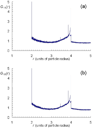
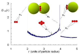
We first show results to support our claim that the reduced-dimension approach produces identical radial distribution functions to those obtained from 3D simulations. In figure 6, we show the pair distribution function for a bimodal pack consisting of particles with a radius ratio of 6.5:1 for our simulation without any reduced-dimension algorithms (inset a) and using the reduced-dimension algorithms and statistics calculation methods (inset b). Although there are very minor differences between the two data sets (due to statistical noise resulting from the finite size of the pack), the data are essentially indistinguishable. (See the text below for a discussion of the pack structure giving rise to the observed resonances in the distribution function.)
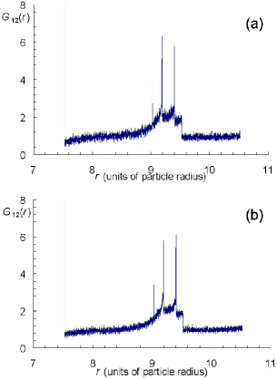
We also show the radial distribution function for this same binary pack in figure 7. Again, the two distributions are essentially identical; the slight variation in peak height for the resonances near is again due to the finite size of the pack. (The data shown in figures 6 and 7 is presented again in figures 10 and 11 in the context of the discussion of the pack microstructure.)
Our radial distribution function for a monomodal pack follows closely that of Donev, Torquato and Stillinger Donev et al. (2005), with two notable exceptions. First, we do not observe the divergence near contact (where is the range away from contact). We ascribe this to the nature of our simulation, which places particles at a stability point in a static configuration, rather than allowing them to reorient dynamically as in other simulations. Second, we measure the “second split peak” at (where is the particle radius), but the strength of this resonance is much smaller in our packs than in the earlier work Donev et al. (2005); in particular, the shoulders of the resonance are much less pronounced; see Fig. 8. The fact that this peak is less pronounced in our pack suggests that the pack is less ordered, and may be responsible in part for the known decrease in packing density that exists for packs created with the ballistic deposition method.
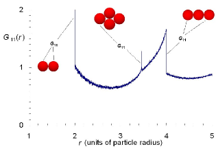
The pair distribution functions in binary packs exhibit rich structure of a similar character to that shown in Fig. 8, but with more features. For example, the pair distribution function for a binary pack with radius ratio 3:1 shows that the peak observed at in the monomodal pack splits into two peaks. Some of the particles that give rise to this feature in the monomodal pack (the “line” of three particles) are wrapped around the surface of the larger particle in the binary pack, so that the peak splits; see Fig. 9.
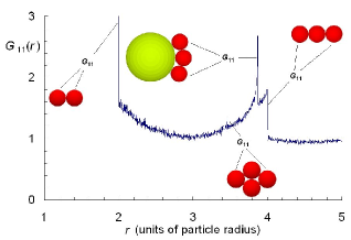
Increasing the size of the second particle in the binary pack above 4:1 shows that an additional resonance arises near the peak at . This additional resonance comes from a line of three smaller particles that wrap around the roll corridor formed by two larger particles. The roll corridor has a smaller radius than the radius of the larger particle, yielding the satellite peak at smaller . This resonance does not occur in binary packs with a size ratio of less than 4:1 because in that case, the smaller particles protrude beyond the roll corridor formed by the larger particles, preventing formation of this configuration. (See Fig. 10). We note that this resonance (near ) is qualitatively different from the others. In essence, the jammed state of this particle configuration affords no room for the particles to shift slightly from the default positions, so that the resonance at this value of exhibits a delta-function behavior. The other resonances have shoulders as approaches the resonance, indicating slight variations in these configurations. Note that the high resolution with which we measure the radial distribution functions is a direct consequence of our reduced-dimension approach and the capability to simulate systems with millions of particles with large size differences.
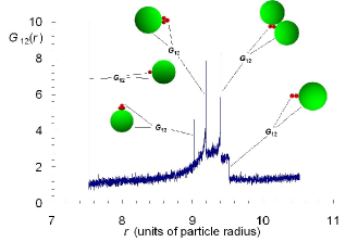
Finally, we consider for a binary mixture (mass ratio 25% fine) with a radius ratio of 6.5:1. This function exhibits resonances not seen, for example, in for a particle size ratio of 3:1. In particular we find a delta-function resonance near . This resonance arises from a tetrahedron of small particles whose base is in contact with the larger particle. Similar to that shown in Fig. 10, this resonance demonstrates no freedom of slight movement for the particle atop the tetrahedron, in turn yielding a delta-function resonance at this value of ; see Fig. 11. Smaller size ratios do not exhibit this feature, presumably because the tetrahedron cannot form on the surface unless the size ratio is large enough.
VI.3 A note about jamming
The pair distribution functions produced from our simulation exhibit features commonly associated with jamming Donev et al. (2005). However, the resonances found in the distribution functions simply arise from ordered sets of particles in contact, and are not definitive proof of jamming. Recent work has placed the understanding and qualification of jamming on a rigorous foundation Donev et al. (2004b); Torquato and Stillinger (2001).
At first blush, our simulation appears to produce hard-sphere packings that cannot be jammed according to these recent definitions. For example, the outer cylinders may contain particle that “hang” in mid-air (i.e., supported by virtual particles). However, we have verified by direct calculation that, in the innermost cylinder (which by design is meant to replicate a “3D” packing), each particle is in fact locally jammed Torquato and Stillinger (2001), in that each particle has at least 4 contacts with other particles, not all of which are in the same hemisphere. (As is common to other numerically-simulated systems, our simulation produces a very small number of “rattlers”, or particles with only three contacts; the typical abundance of such particles is about 0.1% by number in a monomondal, 3D simulation.) These observations suggest that further work on the subject of jamming in a reduced-dimension simulation might prove fruitful, and is one of our active lines of investigation.
VII Conclusion
In summary, we have demonstrated a new, reduced-dimension, Monte Carlo ballistic deposition algorithm that allows analysis of multimodal hard-sphere systems. The simulation produces radial distribution functions which were heretofore unavailable for hard-sphere systems with large particle size differences. These distribution functions exhibit resonances associated with particle configurations found in the pack microstructure. This microstructure information is important for researchers attempting to determine macroscopic material properties using ab initio, first principles calculations. These results also suggest that this simulation technique may be a useful tool for further study of order in hard-sphere systems with diverse particle sizes.
VIII acknowledgments
The authors would like to acknowledge and thank Micheal Iverson of ATK Thiokol for sharing his expertise with the design and development of the packing simulation and pack viewing software.
References
- Bernal (1959) J. D. Bernal, Nature 183, 141 (1959).
- Bernal (1960) J. D. Bernal, Nature 185, 68 (1960).
- Scott and Kilgour (1969) G. D. Scott and D. M. Kilgour, Brit. J. Appl. Phys. 2, 863 (1969).
- Martys et al. (1994) N. S. Martys, S. Torquato, and D. P. Bentz, Phys. Rev. E 50, 403 (1994).
- Truskett et al. (2000) T. M. Truskett, S. Torquato, and P. G. Debenedetti, Phys. Rev. E 62, 993 (2000).
- Kim and Munakata (2003) K. Kim and T. Munakata, Phys. Rev. E 68, 021502 (2003).
- O’Hern et al. (2001) C. S. O’Hern, S. A. Langer, A. J. Liu, and S. R. Nagel, Phys. Rev. Lett. 86, 111 (2001).
- Kadanoff (1999) L. P. Kadanoff, Rev. Mod. Phys. 71, 435 (1999).
- Makse and Kurchan (2002) H. A. Makse and J. Kurchan, Nature 415, 614 (2002).
- Bennett (1972) C. H. Bennett, J. Appl. Phys. 43, 2727 (1972).
- Srolovitz et al. (1981) D. Srolovitz, T. Egami, and V. Vitek, Phys. Rev. B 24, 6936 (1981).
- Coelho et al. (1997) D. Coelho, J.-F. Thovert, and P. M. Adler, Phys. Rev. E 55, 1959 (1997).
- Donev et al. (2004a) A. Donev, I. Cisse, D. Sachs, E. A. Variano, F. H. Stillinger, R. Connelly, S. Torquato, and P. M. Chaikin, Science 303, 990 (2004a).
- Berryman (1983) J. G. Berryman, Phys. Rev. A 27 (1983).
- Jullien et al. (1996) R. Jullien, P. Jund, D. Caprion, and D. Quitmann, Phys. Rev. E 54, 6035 (1996).
- Quintanilla and Torquato (1996) J. Quintanilla and S. Torquato, Phys. Rev. E 54, 5331 (1996).
- Rintoul and Torquato (1996a) M. D. Rintoul and S. Torquato, J. Chem. Phys. 105, 9258 (1996a).
- Rintoul and Torquato (1996b) M. D. Rintoul and S. Torquato, Phys. Rev. Lett. 77, 4198 (1996b).
- Kansal et al. (2000) A. R. Kansal, T. M. Truskett, and S. Torquato, J. Chem. Phys. 113, 4844 (2000).
- Torquato and Stillinger (2001) S. Torquato and F. H. Stillinger, J. Phys. Chem. B 105, 11849 (2001).
- Kansal et al. (2002) A. R. Kansal, S. Torquato, and F. H. Stillinger, Phys. Rev. E 66, 041109 (2002).
- Reichert and Schilling (1984) P. Reichert and R. Schilling, Phys. Rev. B 30, 917 (1984).
- Speedy (1998) R. J. Speedy, J. Phys. Condens. Matter 10, 4387 (1998).
- Onoda and Liniger (1990) G. Y. Onoda and E. G. Liniger, Phys. Rev. Lett. 64, 2727 (1990).
- Yang et al. (1996) A. Yang, C. T. Miller, and L. D. Turcoliver, Phys. Rev. E 53, 1516 (1996).
- Yang et al. (2000) R. Y. Yang, R. P. Zou, and A. B. Yu, Phys. Rev. E 62, 3900 (2000).
- Torquato et al. (2000) S. Torquato, T. M. Truskett, and P. G. Debenedetti, Phys. Rev. Lett. 84, 2064 (2000).
- O’Hern et al. (2003) C. S. O’Hern, L. E. Silbert, A. J. Liu, and S. R. Nagel, Phys. Rev. E 68, 011306 (2003).
- Donev et al. (2004b) A. Donev, S. Torquato, F. H. Stillinger, and R. Connelly, J. Appl. Phys. 95, 989 (2004b).
- McGeary (1961) R. K. McGeary, J. Am. Cer. Soc. 44, 513 (1961).
- Scott and Kilgour (1964) G. D. Scott and D. M. Kilgour, J. Phys. D: Appl. Phys. 2, 863 (1964).
- Finney (1970) J. L. Finney, Proc. R. Soc. A 319, 479 (1970).
- Pouliquen et al. (1997) O. Pouliquen, M. Nicolas, and P. D. Weidman, Phys. Rev. Lett. 79, 3640 (1997).
- Matheson (1974) A. J. Matheson, J. Phys. C: Solid State Phys. 7, 2569,2576 (1974).
- Visscher and Bolsterli (1972) W. M. Visscher and M. Bolsterli, Nature 239, 504 (1972).
- Jodrey and Tory (1985) W. S. Jodrey and E. M. Tory, Phys. Rev. A 32, 2347 (1985).
- Tobochnik and Chapin (1988) J. Tobochnik and P. M. Chapin, J. Chem. Phys. 88, 5824 (1988).
- He et al. (1999) D. He, N. N. Ekere, and L. Cai, Phys. Rev. E 60, 7098 (1999).
- O’Hern et al. (2002) C. S. O’Hern, S. A. Langer, A. J. Liu, and S. R. Nagel, Phys. Rev. Lett. 88, 075507 (2002).
- Lubachevsky and Stillinger (1990) B. D. Lubachevsky and F. H. Stillinger, J. Stat. Phys. 60, 561 (1990).
- Lubachevsky et al. (1991) B. D. Lubachevsky, F. H. Stillinger, and E. N. Pinson, J. Stat. Phys. 64, 501 (1991).
- Elliot and Windle (2000) J. A. Elliot and A. H. Windle, in Sixth Euorpean SGI/Cray MPP Workshop (Manchester Research Center for Computational Science, 2000).
- Davis et al. (1993) I. L. Davis, R. L. Hatch, M. Yener, and K. Chompooming, Phys. Rev. B 47, 2530 (1993).
- Davis (1999) I. L. Davis, Cur. Op. Sol. State Mat. Sci. 4, 505 (1999).
- Hubner et al. (1999) C. Hubner, E. Geibler, P. Elsner, and P. Eyerer, Propellants, Explosives, Pyrotechnics 24, 119 (1999).
- (46) R. L. Hatch.
- Kochevets et al. (2001) S. Kochevets, J. Buckmaster, T. L. Jackson, and A. Hegab, J. Prop. Power 17, 883 (2001).
- Davis and Carter (1990) I. L. Davis and R. G. Carter, J. Appl. Phys. 67, 1022 (1990).
- Cusack (1987) N. E. Cusack, The Physics of Structurally Disordered Matter (Adam Hilger, Bristol and Philadelphia, 1987).
- Mason (1968) G. Mason, Nature 217, 733 (1968).
- Scott (1960) G. D. Scott, Nature 188, 908 (1960).
- Donev et al. (2005) A. Donev, S. Torquato, and F. H. Stillinger, Phys. Rev. E 71, 011105 (2005).