Universal set of quantum gates for double-dot spin qubits with fixed interdot coupling
Abstract
We propose a set of universal gate operations for the singlet-triplet qubit realized by two electron spins in a double quantum dot, in the presence of a fixed inhomogeneous magnetic field. All gate operations are achieved by switching the potential offset between the two dots with an electrical bias, and do not require time-dependent control of the tunnel coupling between the dots. We analyze the two-electron dynamics and calculate the effective qubit rotation angle as a function of the applied electric bias. We present explicit gate sequences for single-qubit rotations about two orthogonal axes, and a CNOT gate sequence, completing the universal gate set.
pacs:
03.67.Pp,73.21.La,85.75.-dElectron spins in semiconductor quantum dots (QDs) are promising candidates for encoding and manipulating quantum information in the solid state. Initialization, manipulation and readout of electron spins have already been demonstrated in these systems Petta ; DelftRO . Proposals exist for encoding one logical qubit in one LD , two Levy ; WuLidar ; ByrdLidar , three DiVincenzo ; Kyriakidis2005 , or even more Meier spins. Although they differ in many respects, a common essential ingredient of all these proposals is electrical control of the two-electron exchange interaction in a double quantum dot, which is characterized by the singlet-triplet energy splitting .
Conventionally, control over is envisioned through voltage control of the tunnel coupling between the two dots. However, in many QD systems, such as vertical pillars Ono2002 , self-assembled dots SAdots , nanowires NWs , or etched dots in Si SiDots , is fixed by growth or fabrication parameters. Even for double QDs (DQDs) in electrically gated systems, such as GaAs dots JeroPRB2003 and carbon nanotubes Mason , fast control over the tunnel coupling is challenging and has not been demonstrated thus far.
A possible way around this problem was demonstrated in a recent experiment by Petta et al. Petta , where is controlled by the misalignment between the two QDs. In contrast to the tunnel coupling, the misalignment can easily be changed over a wide range on a subnanosecond timescale by pulsing the source-drain bias HayashiPRL2003 or a gate voltage Petta . Building on this result, Taylor et al. Taylor proposed a set of universal gates for a logical qubit whose basis states are the two-electron states and . However, their scheme requires to be tunable to zero, which is not possible by changing alone footnote1 . Therefore, voltage control of is still needed in their scheme.
Here, we propose a set of universal quantum gates for the qubit in a constant small inhomogeneous field, that eliminates the need for controlling the tunnel coupling . We demonstrate how arbitrary single-qubit rotations can be performed at finite , by combining Z rotations with rotations around an axis in the XZ plane. We discuss the experimental requirements for this scheme and compare them to current-day devices. Finally, we outline a two-qubit CNOT operation, which is based on a change in the rotation angle of the target qubit that is conditional on the control qubit through spin-dependent tunneling and the capacitive coupling between qubits.
Tunable spin dynamics in a DQD–Our qubit is realized in the and states of two electrons in a double quantum dot, where and are the lowest-energy singlet and triplet states. The dynamics of these states can be described by the Hamiltonian
| (1) |
in the basis , , , footnote-triplets . Here, () denotes the number () of electrons in dot (), is the inhomogeneous magnetic field between the dots and is the difference in Coulomb energy between the and the or state.
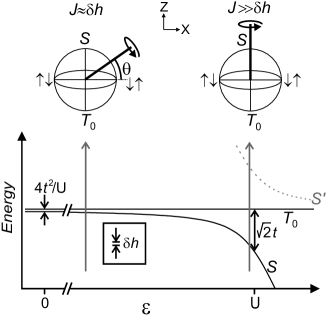
Figure 1 shows the energy of the lowest eigenstates as a function of for =0. In this case, the eigenstates are pure spin states for all values of and we define the qubit basis states as the triplet and the lowest-energy singlet , which are separated by an energy . At , there is an avoided crossing of the and states, and as a consequence is large at this point. In the presence of an inhomogeneous field with magnitude much smaller than (as in the inset of Fig. 1), and remain eigenstates near where . Far away from the avoided crossing, however, and therefore and are strongly mixed. As a consequence, the qubit rotates about an axis determined by and .
The qubit subspace is energetically separated from the two remaining singlets (away from the avoided crossing, the gap is ). Therefore, under the condition that is always changed adiabatically with respect to the energy difference between the qubit states and all other states, the Hamiltonian (1) can be reduced to the qubit subspace and, in the qubit basis and , has the general form
| (2) |
where we have chosen the zero of energy mid-way between the states and and introduced a pseudo-spin notation with Pauli matrices in the two-dimensional qubit subspace. The pseudo-magnetic field is , where the exchange coupling and effective difference field are functions of , , , and . In what follows, will be real and thus the pseudo-field always lies in the -plane (Fig. 1). The angle of the pseudo-field with the axis is
| (3) |
and can be controlled by changing the electric bias , while keeping , , and fixed. Single-qubit rotations can be carried out by switching between two different values of the electric bias , as shown in Fig. 1. One of these working points is chosen to lie close to the avoided crossing, , where (Fig. 1, right). At this point, points into the direction on the Bloch sphere and has a magnitude . The other working point is chosen far from the avoided crossing, (Fig. 1, left) where the pseudo-field lies close to the axis and . In theory, can be made to align with by switching to zero. However, as we wish not to rely on this fast control of , we assume is fixed and therefore remains finite. Thus, we cannot reach a point where lies in the equator plane, i.e., we have to work with a finite angle .
Single-qubit gates–We now show that arbitrary single-qubit rotations can be constructed from the two available elementary operations: (i) rotations about the -tilted axis by some angle , being the switching time,
| (4) |
and (ii) nearly perfect rotations by , given by the diagonal matrix with diagonal entries and . Arbitrary single-qubit rotations can be constructed using the Euler angle method, if rotations by arbitrary angles about two orthogonal axes are available. Therefore, it is sufficient to show that arbitrary rotations about the axis, , in addition to the -rotations, are feasible. The three-step sequence
| (5) |
with the rotation angles footnote-solution
| (6) | |||||
| (7) |
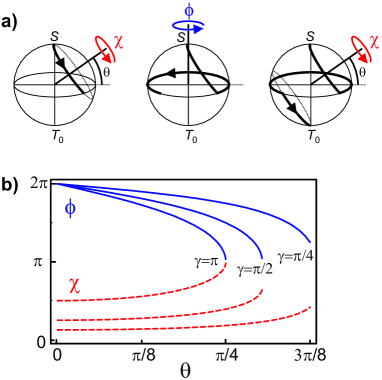
generates a rotation about the -axis by an arbitrary angle , as long as . One can intuitively understand this sequence by following the state on the Bloch sphere; Fig. 2a depicts the three steps for a rotation from to (). We note that switching between the working points has to be performed non-adiabatically with respect to . The rotation angles and are plotted as a function of in Fig. 2b for three different -rotation angles . For a -flip about the axis, , we find the simpler expressions,
| (8) |
We note that the sequence Eq. (5) is not simply one of the known NMR sequences. Actually, in NMR it is usually not a problem to perform rotations about an axis in the equator plane of the Bloch sphere Vandersypen .
Doing nothing– A convenient “idle” position would be close to the avoided crossings , i.e. close to the Z-gate operation point, as here only Z-rotations need to be accounted for. A disadvantage of this position is that the qubit is more susceptible to decoherence from charge fluctuations, due to the different orbital characters of the basis states close to the avoided crossing HuDasSarmaPRL06 . The best waiting position in terms of coherence is probably the symmetric point . However, since and are of the same order at , the spin constantly rotates about the pseudo-field oriented between the and axes at the angle from the axis. To erase this effect, one could always wait for an integer number of full periods, . Alternatively, a pulse sequence similar to refocusing in NMR Vandersypen can be applied,
| (9) |
where and are angles determined by the waiting position and time, and follows from and as
| (10) |
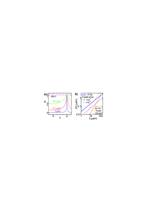
Experimental requirements–To gain insight into the experimental parameters, we have numerically calculated as a function of at fixed values of , , and by diagonalizing (1); the result is shown in Fig. 3(a).
(Explicit expressions for and can be obtained for by way of a Schrieffer-Wolff transformation BI ).
Since we assume that is fixed, the angle will never be exactly , which is required for perfect Z rotations. The desired values of and therefore depend on the error that can be tolerated (see Fig. 3(b)), with typically exceeding by more than an order of magnitude. For the X rotations we need , which gives , which can be satisfied by moving away from the avoided crossing. The minimum value of needed for the X rotation is given in Fig. 3(b) for two typical values of . We note that more detailed calculations including higher orbitals yield a lower () value of EPAPS .
In most systems, can be set by gates or fabrication parameters to anything between and . Several methods exist for creating an inhomogeneous field : (i) application of an inhomogeneous magnetic field, (ii) different -factors in the two dots–either by composition or confinement gfactorcomp –in combination with a homogeneous magnetic field, and (iii) inhomogeneous nuclear polarizations Lai2006 . Note that the effect of a fluctuating nuclear field can be diminished by bringing it into an eigenstate Nuclearfield . The electrical bias , finally, can be controlled in all quantum dot systems listed in the introduction, by pulsing the source, drain or gate voltage footnote-t .
The switching speed of the bias is limited by adiabaticity constraints: switching should be sufficiently fast to guarantee non-adiabatic switching within the qubit subspace, , but not exceedingly fast, to avoid transitions out of the computational space to the higher orbital states, such as the singlet S’ in Fig. 1 (, away from the avoided crossing).
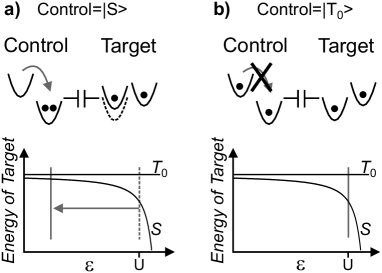
Controlled-NOT gate–To complete our universal set of quantum gates, we require a suitable two-qubit operation, e.g., the controlled-NOT (CNOT, or quantum XOR) gate that flips the target qubit () if the control qubit is in state , and otherwise leaves the target unchanged. This can be achieved by applying a bias voltage on the control qubit, such that its charge state partly shifts to if the qubit state is , but remains mostly in if the state is because the triplet state is far away in energy Petta ; Cphase . Due to the Coulomb interaction between the control and the target qubit, the target qubit will experience a conditional bias shift (see Fig. 4), that can be of the same order as the interdot Coulomb energy within a single logical qubit.
The CNOT is a conditional -rotation by , thus it is natural to use a sequence analogous to Eq. (5),
| (11) |
where and are given in Eq. (8) in terms of and at the conditional bias point , induced by the charge movement in the control qubit, and is the single-qubit -rotation. The conditional rotations about the -axis are analogous to , but instead of being induced by a direct manipulation of the bias , they are controlled by applying to the control qubit, which results in a conditional bias at the target qubit.
The sequence Eq. (11) for is not a true CNOT yet, because (i) the -rotation is not conditional on the control qubit being in state , but is in fact always carried out, and (ii) the conditional rotations also perform a -rotation in case the control qubit is in state . In summary, does a NOT operation (-rotation by ) on the target if the control is and a -rotation by if the control is in state . The true CNOT operation does nothing on the target qubit if the control is in ; it can be obtained with the sequence
| (12) |
canceling the undesired phases if the control qubit is .
In conclusion, we have proposed a universal set of quantum gates for the qubit, consisting of single-qubit rotations about two orthogonal axes and about arbitrary angles combined with the CNOT gate. The electrical bias is the only parameter that needs to be tuned fast and with high precision, which considerably relaxes the experimental requirements compared to previous spin-based qubit control proposals and makes our scheme applicable to virtually any quantum dot system.
This research was supported in part by the NSF under Grant No. PHY99-07949. We thank the KITP at UCSB, where this work was initiated. RH is supported by AFOSR, DARPA/MARCO, DARPA/CNID, and ARO; GB acknowledges funding from the Swiss National Science Foundation and NCCR Nanoscience Basel.
References
- (1) J. R. Petta et al., Science 309, 2180 (2005).
- (2) R. Hanson et al., Phys. Rev. Lett. 94, 196802 (2005).
- (3) D. Loss, D. P. DiVincenzo, Phys. Rev. A 57, 120 (1998).
- (4) J. Levy, Phys. Rev. Lett. 89, 147902 (2002).
- (5) L.-A. Wu and D. A. Lidar, Phys. Rev. A 65, 042318 (2002); Phys. Rev. A 66, 062314 (2002).
- (6) M. S. Byrd and D. A. Lidar, Phys. Rev. Lett. 89, 047901 (2002).
- (7) D. P. DiVincenzo, D. Bacon, J. Kempe, G. Burkard, and K. B. Whaley, Nature 408, 339 (2000).
- (8) J. Kyriakidis and S. J. Penney, Phys. Rev. B 71, 125332 (2005).
- (9) F. Meier, J. Levy, and D. Loss, Phys. Rev. Lett. 90, 047901 (2003).
- (10) K. Ono, D. G. Austing, Y. Tokura and S. Tarucha, Science 297, 1313 (2002).
- (11) M. Bayer et al., Science 291, 451 (2001); B. D. Gerardot et al., Phys. Rev. Lett. 95, 137403 (2005); T. Ota et al., Phys. Rev. Lett. 95, 236801 (2005); E.A. Stinaff et al., Science 311, 636 (2006).
- (12) M. T. Björk et al., Nano Lett. 4, 1621 (2004).
- (13) J. Gorman, D.G. Hasko and D.A. Williams, Phys. Rev. Lett. 95, 090502 (2005).
- (14) J. M. Elzerman et al., Phys. Rev. B 67, 161308 (2003).
- (15) N. Mason, M. J. Biercuk, and C. M. Marcus, Science 303, 655 (2004).
- (16) T. Hayashi et al., Phys. Rev. Lett. 91, 226804 (2003).
- (17) J. M. Taylor et al., Nature Physics 1, 177 (2005); J. M. Taylor et al., cond-mat/0602470.
- (18) Note that is predicted to go to zero in a finite perpendicular magnetic field BLD ; Kyriakidis2002 , but such a relatively large field also closes the essential single-dot singlet-triplet gap.
- (19) G. Burkard, D. Loss, and D. P. DiVincenzo, Phys. Rev. B 59, 2070 (1999).
- (20) J. Kyriakidis et al., Phys. Rev. B 66, 035320 (2002).
- (21) We only consider the states with spin projection . The triplet states with can be efficiently decoupled from the subspace by chosing purely along and by applying a magnetic field along . Note that choosing in the plane of the dots is preferable to minimize effects of on the orbitals. See EPAPS for details.
- (22) See EPAPS Document No. E-PRLTAO-98-036706. For more information on EPAPS, see http://www.aip.org/pubservs/epaps.html.
- (23) The angles and are obtained by solving the transcendental equations Eq. (5).
- (24) L. M. K. Vandersypen and I. L. Chuang, Rev. Mod. Phys. 76, 1037 (2005).
- (25) X. Hu, S. Das Sarma, Phys. Rev. Lett. 96, 100501 (2006).
- (26) G. Burkard and A. Imamoglu, Phys. Rev. B 74, 041307(R) (2006).
- (27) M.J. Snelling et al., Phys. Rev. B 44, 11345 (1991); G. Salis et al., Nature (London) 414, 619 (2001); M. T. Björk et al., Phys. Rev. B 72, 201307 (2005).
- (28) C. W. Lai, P. Maletinsky, A. Badolato, and A. Imamoglu, Phys. Rev. Lett. 96, 167403 (2006).
- (29) D. Stepanenko, G. Burkard, G. Giedke, A. Imamoglu, Phys. Rev. Lett. 96, 136401 (2006); D. Klauser, W. A. Coish, D. Loss, Phys. Rev. B 73, 205302 (2006).
- (30) For some systems, might have a weak dependence on which could easily be accounted for in Eq. (1).
- (31) The controlled-phase gate proposed in Ref. Taylor can also be used here, as it does not require control over .