Explanation of the discrepancy between the measured and atomistically calculated yield stresses in body-centered cubic metals
Abstract
We propose a mesoscopic model that explains the factor of two to three discrepancy between experimentally measured yield stresses of BCC metals at low temperatures and typical Peierls stresses determined by atomistic simulations of isolated screw dislocations. The model involves a Frank-Read type source emitting dislocations that become pure screws at a certain distance from the source and, owing to their high Peierls stress, control its operation. However, due to the mutual interaction between emitted dislocations the group consisting of both non-screw and screw dislocations can move at an applied stress that is about a factor of two to three lower than the stress needed for the glide of individual screw dislocations.
pacs:
I Introduction
It has been firmly established by many experimental and theoretical studies performed in the last forty years that the plastic behavior of body-centered-cubic (BCC) metals is controlled by screw dislocations the cores of which are non-planar (for reviews see Kubin (1982); Christian (1983); Duesbery (1989); Vitek (1992); Seeger (1995); Pichl (2002); Duesbery et al. (2002)). However, the only direct experimental observation that suggests such core spreading is the high-resolution transmission electron microscopic (TEM) study of Sigle Sigle (1999) while the primary source of our understanding of the dislocation core structure and related atomic-level aspects of the glide of screw dislocations is computer simulation. Such calculations have been made using a broad variety of descriptions of interatomic forces, ranging from pair-potentials Vitek et al. (1970); Basinski et al. (1971); Duesbery et al. (1973) to density functional theory (DFT) based calculations Woodward and Rao (2001, 2002); Frederiksen and Jacobsen (2003) and studies employing other quantum mechanics based methods Xu and Moriarty (1996, 1998); Mrovec et al. (2004).
The vast majority of atomistic studies of the core structure and glide of screw dislocations in BCC metals were carried out using molecular statics techniques and thus they correspond to 0 K. A problem encountered universally in all the calculations of the critical resolved shear stress (CRSS), i.e. the Peierls stress, at which the screw dislocation starts to glide, is that it is by a factor of two to three larger than the CRSS obtained by extrapolating experimental measurements of the yield and flow stresses to 0 K. The following are a few examples. Basinski et al. Basinski et al. (1981) measured the flow stress of potassium in the temperature range 1.5 K to 30 K and extrapolated to 0 K to get to where is the shear modulus and , , are elastic constants. Similar values were found by Pichl and Krystian Pichl and Krystian (1997). The values of the CRSS when the maximum resolved shear stress plane (MRSSP) is a plane, calculated using a pair potential derived on the basis of the theory of weak pseudopotentials Dagens et al. (1975), is to Basinski et al. (1981). More recently, Woodward and Rao Woodward and Rao (2002) calculated the CRSS in molybdenum using the many-body potentials derived from the generalized pseudopotential theory Moriarty (1990) and a DFT based method. When the MRSSP is a plane, they found the CRSS to be between and . A similar value of the CRSS, , was found in calculations employing the tight-binding based bond-order potential for molybdenum Mrovec et al. (2004); Gröger and Vitek (2005). Experimental measurements of Hollang et al. Hollang et al. (2001), extrapolated to 0 K, give for the CRSS in molybdenum . A similar problem was encountered by Wen and Ngan Wen and Ngan (2000) who used the Embedded Atom Method (EAM) potential for iron and the Nudged Elastic Band method to analyze the activation enthalpies for kink-pair nucleation on screw dislocations. The calculated yield stress at 0 K was about while the experimental values, reported by Aono et al. Aono et al. (1981) are to . This ubiquitous higher value of the calculated CRSS, found independently of atomic interactions, suggests that the origin of this discrepancy cannot be sought on the atomic scale of the motion of individual dislocations but rather on mesoscopic scale where a large number of elastically interacting dislocations glide at the same time. In this context it should be noticed that the only atomistic simulation that predicts yield stress close to that measured experimentally considered a planar dislocation network of and screw dislocations with screw junctions Bulatov and Cai (2002). Such a network moved in the plane at the stress about lower than the Peierls stress of an isolated screw dislocation.
In-situ TEM observations of dislocation sources in BCC transition metals showed that in thin foils straight screw dislocations formed near the source and moved very slowly as a group Vesely (1968); Louchet and Kubin (1975); Matsui and Kimura (1976); Takeuchi and Maeda (1977); Louchet et al. (1979); Vesely (2002); Louchet (2003). Hence they fully control the rate at which the source produces dislocations. In the foils used in TEM the applied stresses are very low but a similar control of the sources by sessile screw dislocations can be expected in the bulk at stresses leading to the macroscopic yielding. However, at higher stresses dislocations move faster and do not become pure screws immediately after leaving the source but at a distance from the source. Indeed, even in situ observations at higher stresses do not show straight screw dislocations emanating directly from the sources Vesely (2006).
In this paper, we propose a mesoscopic model involving a Frank-Read type source Hirth and Lothe (1982) emitting dislocations of generally mixed character that become pure screw dislocations at a distance from the source and, owing to their high Peierls stress, control its operation. However, there are a number of non-screw dislocations between the screws and the source, which can move easily. These dislocations exert a stress on the screw dislocations and this stress, together with the applied stress, act on the screw dislocations by the force equal to that needed to overcome the Peierls stress. Screw dislocations can then move at an applied CRSS that is about a factor of two to three lower than the CRSS needed for the glide of individual screw dislocations.
II Model of dislocation nucleation and motion
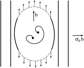
Let us consider a Frank-Read source (see e.g. Hirth and Lothe (1982)) that produces dislocations in a BCC metal. It emits, as always, dislocation loops that have a mixed character and expand easily away from the source since their Peierls stress is low. However, at a certain distance from the source, a significant part of the expanding loop attains the screw orientation and becomes much more difficult to move owing to the very high Peierls stress of pure screws. The rest of the loop, having a mixed character, continues to expand which leads to further extension of the screw segments. As a result, the source becomes surrounded by arrays of slowly moving screw dislocations, as depicted schematically in Fig. 1. Further operation of the source is hindered by their back stress and effectively controlled by the ability of the screw dislocations to glide.
The operation of the source is driven by the applied stress, , which acts by the Peach-Koehler force Hirth and Lothe (1982) (per unit length) on the dislocation that bows out. This dislocation obviously has a mixed character. Let us consider now that there are screw dislocations at distances from the source and dislocations, generally of mixed character, positioned between the source and the screw dislocations. We approximate the latter as straight lines of the same orientation as the screws, positioned at distances from the source, but with a negligible Peierls stress compared to that of the screws. In the framework of the isotropic elastic theory of dislocations the condition for the source to operate is then
| (1) |
where is the line tension of the emitted dislocations, their Burgers vector, the half-length of the source, the shear modulus, and , constants of the order of unity. The first term is the force arising from the line tension that pulls the dislocation back and the second and third terms are forces produced by the stress fields of screw and non-screw dislocations, respectively, present ahead and/or behind the source. In the following we neglect the interaction between dislocations ahead and behind the source as they are far apart. Moreover, the dislocation sources are frequently single-ended (see e.g. Hirth and Lothe (1982)). Hence we analyze only dislocations ahead of the source, i.e. those towards which the source bows out.
It should be noted here that the screw dislocations in the array ahead of the source are not pressed against any obstacle and thus they do not form a pile-up. Within the approximations defined above, the th screw dislocation will move provided
| (2) |
where is the Peierls stress of screw dislocations. The second and third terms are stresses arising from screw and non-screw dislocations, respectively, and the fourth term is the stress arising from the dislocation associated with the source that is also treated as a straight line of the same type as all the other mixed dislocations. Since the Peierls stress of non-screw dislocations is negligible, the th non-screw dislocation can move provided
| (3) |
The meanings of individual terms are analogous to those in equation (2).
Now, the question asked is how large stress, , needs to be applied so that the screw dislocations can move so far away from the source that they either reach a surface or encounter dislocations of opposite sign from another source and annihilate. In both cases the source then keeps producing new dislocations indefinitely. In the former case these dislocations keep vanishing at the surface and the latter case leads to the propagation of slip through the sample. In order to investigate the problem formulated above, we performed the following self-consistent simulations for certain fixed values of the Peierls stress, , and applied stress . First, we choose a half-length of the source, , and a distance from the source, , beyond which the expanding loop always attains the screw character. The first mixed dislocation emitted by the source becomes screw when reaching the distance and then moves to a distance , determined by equation (2). Provided that the source can operate, i.e. the inequality (1) is satisfied, another dislocation is emitted from the source. The position of this dislocation is determined by equation (3) if it does not reach and by equation (2) if it does. Subsequently, the position of the first dislocation, , is updated to satisfy equation (2), which allows also the second dislocation to move. In this way a new position of the first dislocation, , and the position of the second dislocation, either if smaller than or if larger than , are found self-consistently. This self-consistent process is then repeated for the third, fourth, etc., dislocations until the source cannot emit a new dislocation, i.e. when inequality (1) is no longer satisfied. The result of this calculation is the number of screw dislocations, , and mixed dislocations, , as well as their positions ahead of the source, when the source becomes blocked by the back-stress from all the emitted dislocations. The first screw dislocation is then at a position and further operation of the source can proceed only if this screw dislocation is removed, as argued above. The source can then continue operating in a steady-state manner, producing a large number of dislocations that mediate the macroscopic plastic flow.
III Results
In the following numerical simulations the applied stress, , has been set equal to and , respectively, in order to investigate whether the source can operate at stress levels corresponding to experimental yield stresses extrapolated to 0 K, as discussed in the Introduction. Three values of the Peierls stress, , have been considered that fall into the range found in atomistic studies of transition metals Woodward and Rao (2002); Mrovec et al. (2004); Gröger and Vitek (2005); Wen and Ngan (2000), namely , , and . Three different positions at which mixed dislocations transform into screw ones have been considered, namely and 2000. The dependence on the size of the source, , was also investigated. However, this dependence is very weak since enters only through the line tension term in (1) and this is always small compared to the terms arising from the back-stress of emitted dislocations. Hence, without the loss of generality, we set . The values of parameters and , entering equations (1) to (3) have all been set to one and the usual approximation for the line tension, Hirth and Lothe (1982), adopted.

Results of such simulation are presented in detail for , and in Fig. 2, where positions of the dislocations ahead of the source and stresses acting on them are shown. In this case . It should be noted that the stress exerted on the majority of screw dislocations is practically equal to their Peierls stress. The distances found for the above-mentioned two values of , three values of and three values of , are summarized in Table 1.
| 500 | 1000 | 2000 | ||
| 1.0 | 1.1 | 1.2 | ||
| 1.2 | 1.3 | 1.3 | ||
| 1.2 | 1.2 | 1.2 | ||
| 1.6 | 1.8 | 2.0 | ||
| 1.8 | 2.0 | 2.0 | ||
| 1.9 | 2.0 | 2.0 | ||
These results suggest that, for a given applied stress, the ratio is almost constant, independent of , and only weakly dependent on the magnitude of the Peierls stress . At , most of the dislocations are mixed and . With increasing stress, more emitted dislocations become screw and, at , , which implies that the numbers of mixed and screw dislocations ahead of the source are very similar. Very importantly, the stress exerted on most of the screw dislocations is practically equal to their Peierls stress, see Fig. 2.
IV Conclusion
The distinguishing characteristic of the model presented in this paper is that it does not consider the glide of a single screw dislocation but movement of a large group of dislocations produced by a Frank-Read type source. In general, this source produces dislocation loops of mixed character that transform into pure screws at a distance from the source. Hence, the group of dislocations consists of screw dislocations at distances larger than and non-screw dislocations near the source. It is then the combination of the applied stress with the stress produced by the dislocations in this group that acts on the screw dislocations and is practically equal to their Peierls stress. However, after emitting a certain number of dislocations the source becomes blocked by their back-stress and, at this point, the leading screw dislocation reaches the distance from the source. Nonetheless, the source can continue operating if a dislocation of opposite sign, originating from another source, annihilates the leading screw dislocation. This requires an average separation of sources about . Since the pinning points of the sources for a given slip system are produced by intersections with dislocations in other slip systems, their separation is related to the dislocation density in these systems. For example, in a deformed molybdenum crystal this density is of the order of Kaspar et al. (2000) which implies separation of dislocations between and , for the lattice parameter of Mo equal to . These values are in the range of for applied stresses that are between one-third and one-half of the atomistically calculated Peierls stress for the sources of the size compatible with the above-mentioned density of dislocations.
The implication of the present study is that the values of the Peierls stress of screw dislocations in BCC metals found in atomistic studies cannot be compared directly with the yield stress obtained by extrapolating experimental measurements to 0 K. The experiments do not determine the stress needed for the glide of individual screw dislocations but, instead, the stress needed for the operation of sources that are hindered by the sessile screw dislocations. These sources can operate at stresses lower than the Peierls stress owing to the collective motion of screw and mixed dislocations produced by them, as described in this paper. Consequently, the discrepancy between the calculated Peierls stress and the measured yield stress is not a consequence of the inadequacy of the description of atomic interactions, which has often been raised as a possible explanation, but incorrectness of their direct comparison.
Acknowledgements.
The authors would like to thank Drs. F. Louchet, L. Kubin and D. Vesely for stimulating discussions on experimental observations of screw dislocations in BCC metals. This research was supported by the U.S. Department of Energy, BES Grant no. DE-PG02-98ER45702.References
- Kubin (1982) L. P. Kubin, Rev. Deform. Behav. Mat. 4, 181 (1982).
- Christian (1983) J. W. Christian, Metall. Trans. A 14, 1237 (1983).
- Duesbery (1989) M. S. Duesbery, in Dislocations in Solids, edited by F. R. N. Nabarro (Elsevier, 1989), vol. 8, pp. 66–173.
- Vitek (1992) V. Vitek, Prog. Mater. Sci. 36, 1 (1992).
- Seeger (1995) A. Seeger, J. de Physique IV 5, 45 (1995).
- Pichl (2002) W. Pichl, Phys. Stat. Sol. A 189, 5 (2002).
- Duesbery et al. (2002) M. S. Duesbery, V. Vitek, and J. Cserti, in Understanding materials, edited by C. J. Humphreys (Maney Publishing, 2002), pp. 165–192.
- Sigle (1999) W. Sigle, Phil. Mag. A 79, 1009 (1999).
- Vitek et al. (1970) V. Vitek, R. C. Perrin, and D. K. Bowen, Philos. Mag. 21, 1049 (1970).
- Basinski et al. (1971) Z. S. Basinski, M. S. Duesbery, and R. Taylor, Can. J. Phys. 49, 2160 (1971).
- Duesbery et al. (1973) M. S. Duesbery, V. Vitek, and D. K. Bowen, Proc. R. Soc. London A 332, 85 (1973).
- Woodward and Rao (2001) C. Woodward and S. I. Rao, Phil. Mag. A 81, 1305 (2001).
- Woodward and Rao (2002) C. Woodward and S. I. Rao, Phys. Rev. Lett. 88, 216402 (2002).
- Frederiksen and Jacobsen (2003) S. L. Frederiksen and K. W. Jacobsen, Phil. Mag. 83, 365 (2003).
- Xu and Moriarty (1996) W. Xu and J. A. Moriarty, Phys. Rev. B 54, 6941 (1996).
- Xu and Moriarty (1998) W. Xu and J. A. Moriarty, Comp. Mater. Sci. 9, 348 (1998).
- Mrovec et al. (2004) M. Mrovec, D. Nguyen-Manh, D. G. Pettifor, and V. Vitek, Phys. Rev. B 69, 094115 (2004).
- Basinski et al. (1981) Z. S. Basinski, M. S. Duesbery, and G. S. Murty, Acta Metall. 29, 801 (1981).
- Pichl and Krystian (1997) W. Pichl and M. Krystian, Phys. Stat. Sol. A 160, 373 (1997).
- Dagens et al. (1975) L. Dagens, M. Rasolt, and R. Taylor, Phys. Rev. B 11, 2726 (1975).
- Moriarty (1990) J. A. Moriarty, Phys. Rev. B 42, 1609 (1990).
- Gröger and Vitek (2005) R. Gröger and V. Vitek, Mat. Sci. Forum 482, 123 (2005).
- Hollang et al. (2001) L. Hollang, D. Brunner, and A. Seeger, Mat. Sci. Eng. A 319-321, 233 (2001).
- Wen and Ngan (2000) M. Wen and A. H. W. Ngan, Acta Mater. 48, 4255 (2000).
- Aono et al. (1981) Y. Aono, E. Kuramoto, and K. Kitajima, Reports of Res. Inst. for Appl. Mech. 29, 127 (1981).
- Bulatov and Cai (2002) V. V. Bulatov and W. Cai, Phys. Rev. Lett. 89, 115501 (2002).
- Vesely (1968) D. Vesely, Phys. Stat. Sol. A 29, 675 (1968).
- Louchet and Kubin (1975) F. Louchet and L. P. Kubin, Acta Metall. 23, 17 (1975).
- Matsui and Kimura (1976) H. Matsui and H. Kimura, Mat. Sci. Eng. 24, 247 (1976).
- Takeuchi and Maeda (1977) S. Takeuchi and K. Maeda, Acta Metall. 25, 1485 (1977).
- Louchet et al. (1979) F. Louchet, L. P. Kubin, and D. Vesely, Phil. Mag. A 39, 433 (1979).
- Vesely (2002) D. Vesely, in Understanding materials, edited by C. J. Humphreys (Maney Publishing, 2002), pp. 157–164.
- Louchet (2003) F. Louchet, http://www.gpm2.inpg.fr/axes/plast/ MicroPlast/ddd/TEM/index.php (2003).
- Vesely (2006) D. Vesely, private communication (2006).
- Hirth and Lothe (1982) J. P. Hirth and J. Lothe, Theory of dislocations (J.Wiley & Sons, 1982), 2nd ed.
- Kaspar et al. (2000) J. Kaspar, A. Luft, and W. Skrotzki, Cryst. Res. Technol. 35, 437 (2000).