Domain Wall Assisted Magnetic Recording
Abstract
Using numerical and analytical micromagnetics we calculated the switching fields and energy barriers of the composite (exchange spring) magnetic recording media, which consist of layers with high and low magnetocrystalline anisotropy. We demonstrate that the ultimate potential of the composite media is realized if the interfacial domain wall fits inside the layers. The switching occurs via domain wall nucleation, compression in the applied field, de-pinning and propagation through the hard/soft interface. This domain wall assisted switching results in a significant reduction of the switching field without substantial decrease of the for thermal activation energy barrier. We demonstrate that the Domain Wall Assisted Magnetic Recording (DWAMR) offers up to a three-fold areal density gain over conventional single layer recording.
Areal density is one of the most important figures of merits for the information storage technologies. With the increase of the recording density the dimensions of the magnetic media grains have to be reduced to maintain the signal-to-noise ratio. Reducing grains dimensions results in the decrease of the magnetic energy barrier which leads to the thermally activated loss of the stored information. To increase the thermal stability the magnetic anisotropy of the grains can be increased, however the maximum anisotropy is limited by the write head fields. The described ”trilemma” Richter and Dobin (2005) constitutes the main physical limit that magnetic recording faces in the attempt to achieve the higher recording densities.
As a means to resolve this problem, Victora and Shen proposed the so-called composite media Victora and Shen (2005), which are made of two layers, one of which (”hard”) possesses high magneto-crystalline anisotropy, while the other (”soft”) layer has very low anisotropy. It was shown in Refs. Victora and Shen (2005, in press) that for the optimum exchange coupling across the layers interface the switching field of such a structure may be substantially reduced compared to a single layer film. The concept of exchange spring media, utilizing non-coherent magnetization rotation in hard/soft multilayers to reduce the switching field, was independently introduced by Suess et al. Suess et al. (2005b, a). Guslienko et al. Yu.Guslienko et al. (2004) analyzed the switching field in dual layer media taking into account non-uniform magnetization rotation, and the results were shown Suess et al. (2005a); Garcia-Sanchez et al. (2005) to differ from the ”two-spin” (rigid layers) approximation.
In this Letter we will show that the ultimate potential of the composite (exchange spring) media is realized when the interfacial domain wall fits inside soft and hard layers. We will analyze the potential of the Domain Wall Assisted Magnetic Recording (DWAMR) using numerical micromagnetics as well as analytical formulas derived in Refs. Kronmuller and Goll (2002); Loxley and Stamps (2001) for exchange spring magnets.
In our micromagnetic simulations the hard and soft layers are discretized down to atomic scale (0.2 nm) in the vertical (perpendicular to the film plane) direction. We include the external, anisotropy and vertical exchange fields, however, for simplicity, we do not take into account the effects of inter-granular exchange and demagnetization fields. Therefore our analysis is restricted to a simplified one-dimensional problem, allowing a better qualitative understanding of the underlying physics. Although this analysis cannot be used to quantitatively assess all aspects of recording process, it is applicable, for example, for the bit-patterned media, as well as perpendicular media with demagnetization field fully compensated by the inter-granular (lateral) exchange field.
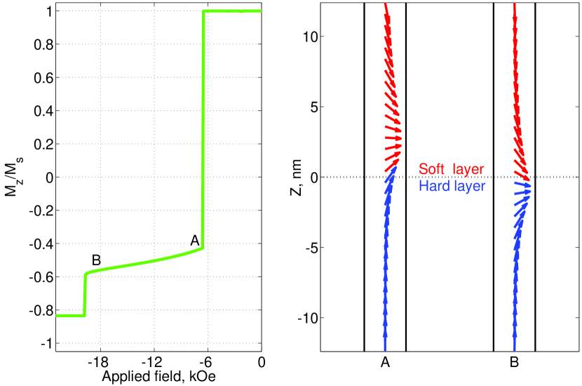
In Fig. 1 an M-H loop and magnetization configurations of a hard/soft structure are presented. The switching of the upper (free) part of the soft layer occurs at the applied field close to the soft layer anisotropy field kOe. At this field the domain wall is pinned near the hard/soft interface mostly in the soft layer (point A). As the applied field increases the domain wall in the soft layer is compressed and it penetrates more and more into the hard layer (point B). Once the applied field reaches 20 kOe the domain wall de-pins from the hard/soft interface and propagates through the entire hard layer. Note, that for the chosen parameters the hard layer switching field is an order of magnitude less than it’s anisotropy field.
For infinitely thick hard and soft layers a simple analytic formula for the switching field was derived and used to study exchange spring magnets Kronmuller and Goll (2002), as well as domain wall propagation in magnetic wires Loxley and Stamps (2001):
| (1) |
Note, that the analytic result was first obtained by Aharoni Aharoni (1960) in the special case . This infinite thickness approximation can be applied to realistic systems with finite layers thicknesses only if the interfacial domain walls fit inside the hard and (more importantly) soft layers.
Using infinite continuous layers approximation, similar to that used in Refs. Kronmuller and Goll (2002); Loxley and Stamps (2001), we can estimate the domain wall thickness in soft or hard layers:
| (2) |
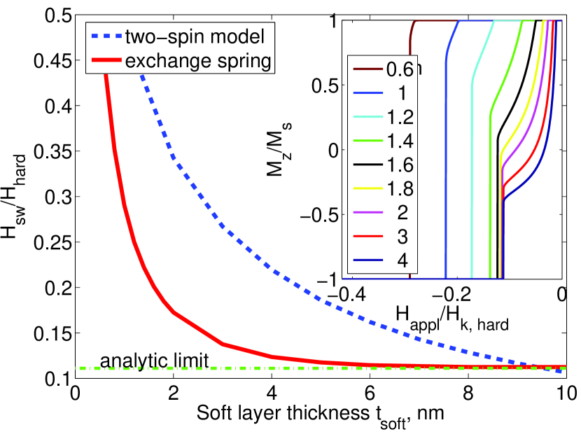
where is the coordinate along the direction perpendicular to the film plane, is the applied field and are anisotropy energy and saturation magnetization of the hard or soft layer, is the magnetization angle at the hard/soft interface . If the anisotropy of the soft material is zero, the domain wall thickness is, of course, infinite in zero applied field. However, as the applied field increases the domain wall starts to compress at the hard/soft interface. For the media parameters from Fig. 1, the domain wall thickness at the switching field kOe is as small as nm. For the domain wall assisted switching mechanism to work efficiently, it is required that the interfacial domain wall fits inside the soft layer, which is demonstrated by simulations in Fig. 2. Once the soft layer thickness reduces below the domain wall thickness nm, the switching field dependence on the soft layer thickness saturates. The limiting value of switching field is in an excellent agreement with the analytic prediction of Eq. (1). In a striking contrast with these findings, the switching field with optimized interlayer exchange coupling for the two-spin model depends on the ratio Richter and Dobin (in press).
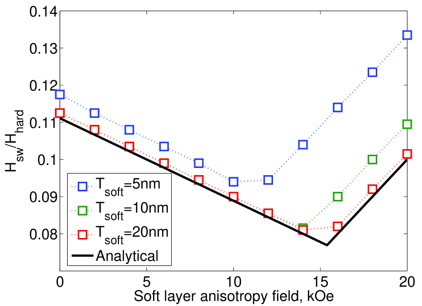
The reduction of the switching field with the soft layer anisotropy, presented in Fig. 3 is another surprising outcome of the domain wall switching mechanism, which is not predicted by the two-layer approximation. The switching field reduction with soft layer anisotropy was first predicted by Hagedorn Hagedorn (1970), who found that in case the minimum switching field is achieved for .
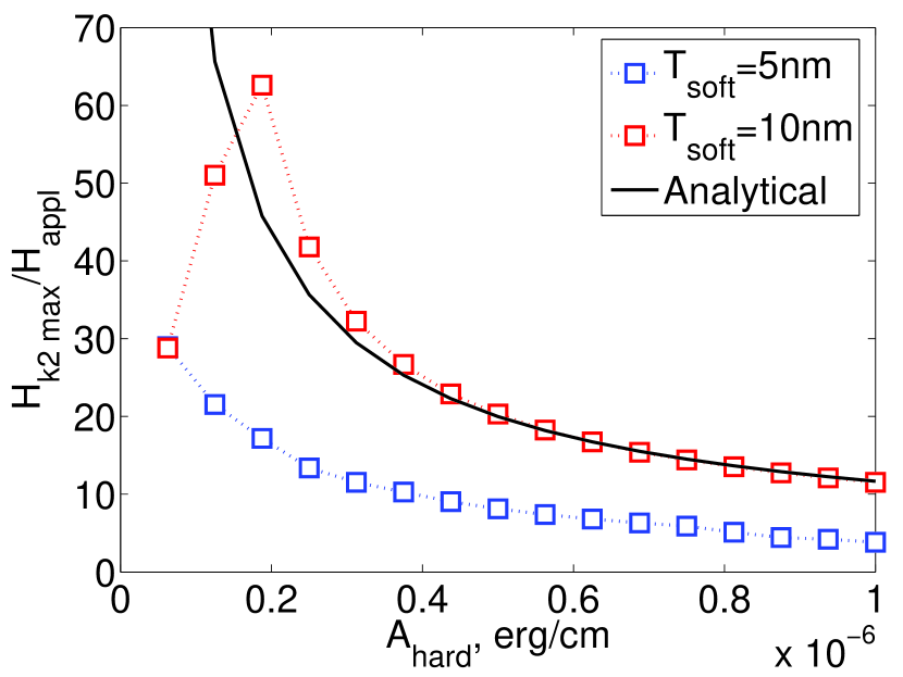
Another interesting feature of the domain wall assisted switching is the dependence of the switching field on the ratio of the exchange stiffness constants in the two layers. In Fig. 4 we present the maximum hard layer anisotropy field that can be switched by a fixed applied field kOe. For the very small hard layer exchange stiffness the applied field of just 15 kOe can switch the hard layer with anisotropy as large as 900 kOe!
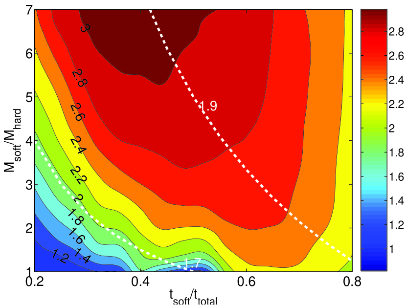
Finally, we assessed the advantage of the DWAMR over the single layer recording using the following scheme. We calculated the maximum energy barrier for a fixed applied field of kOe, varying the magnetizations, anisotropies and thicknesses of the layers, while keeping constant the total thickness of the dual layer structure at nm, and the average magnetization emu/cc. Energy barriers were calculated using a simplified version of the elastic band approach suitable for the present 1D problem Dobin and Richter (to be published). In Fig. 5 the DWAMR energy barrier gain is presented, defined as the ratio of the dual layer energy barrier to the energy barrier of the equivalent single layer (with thickness , saturation magnetization and anisotropy equal to ). In the best conditions DWAMR gain can reach 3, substantially exceeding the maximum value of 2 found in the two-spin model Victora and Shen (2005); Richter and Dobin (in press). The DWAMR gain can be estimated from the following simple arguments, assuming . If domain walls fits inside the soft layer, the switching field (equal to the applied field) does not depend on the layers thicknesses (Eq. 1). Because the soft layer does not store any energy, the thickness of the soft layer has to be minimized to maximize the gain, i.e. for . On the other hand, the hard layer thickness has to be maximized, however if it exceeds certain critical thickness , the energy barrier will not increase with thickness anymore Braun (1994) saturating at the well-known domain wall energy density (per unit area): . Maximum gain is then given by
Interestingly, within this simple approximation, maximum gain depends only on the ratio . This dependence has a very flat maximum for , reaching a value of . The accurate numerical optimization (Fig. 5) yields a 25% lower maximum gain value. The overestimation of the gain in Eq. (Domain Wall Assisted Magnetic Recording) is caused mainly by underestimation of the switching field when Eq. (1) is used for finite soft layer thickness.
Finally, we want to point out the two most important requirements essential for the high DWAMR gains and may present significant challenges to the DWAMR implementation. First, the magnetocrystalline anisotropy of the hard layer has to be as large as 300 kOe to achieve the highest DWAMR gain, with relatively low saturation magnetization of 300 emu/cc. Presently, no materials with such extremely high anisotropies are known to exist, thus the future of the composite/exchange spring/DWAMR depends strongly on the discovery of ultra-hard magnetic materials with good granular structure. Second, the exchange coupling at the hard/soft layers interface needs to be very large, 50% of the bulk exchange energy density value, which would require an extremely delicate growth process.
References
- Richter and Dobin (2005) H. J. Richter and A. Y. Dobin, J. Magn. Magn. Mat. 287, 41 (2005).
- Victora and Shen (2005) R. H. Victora and X. Shen, IEEE Trans. on Magn. 41, 537 (2005).
- Victora and Shen (in press) R. H. Victora and X. Shen, IEEE Trans. on Magn. (in press).
- Suess et al. (2005a) D. Suess, T. Schrefl, S. Fahler, M. Kirschner, G. Hrkac, F. Dorfbauer, and J. Fiedler, Appl. Phys. Lett. 87, 012504 (2005a).
- Suess et al. (2005b) D. Suess, T. Schrefl, R. Dittrich, M. Kirschner, F. Dorfbauer, G. Hrkac, and J. Fidler, J. Magn. Magn. Mat. 287, 41 (2005b).
- Yu.Guslienko et al. (2004) K. Yu.Guslienko, O. Chubykalo-Fesenko, O. Mryasov, R. W. Chantrell, and D. Weller, Phys. Rev. B 70, 104405 (2004).
- Garcia-Sanchez et al. (2005) F. Garcia-Sanchez, O. Chubykalo-Fesenko, O. Mryasov, R. W. Chantrell, and K. Yu.Guslienko, Appl. Phys. Lett. 87, 122501 (2005).
- Kronmuller and Goll (2002) H. Kronmuller and D. Goll, Physica B. 319, 122 (2002).
- Loxley and Stamps (2001) P. N. Loxley and R. L. Stamps, IEEE Trans. on Magn. 37, 2098 (2001).
- Aharoni (1960) A. Aharoni, Phys. Rev. 119, 127 (1960).
- Richter and Dobin (in press) H. J. Richter and A. Y. Dobin, J. Appl. Phys. (in press).
- Hagedorn (1970) F. B. Hagedorn, J. Appl. Phys. 41, 2491 (1970).
- Dobin and Richter (to be published) A. Y. Dobin and H. J. Richter (to be published).
- Braun (1994) H. B. Braun, Phys. Rev. B 50, 16501 (1994).