The Magneto-coulomb effect in spin valve devices
Abstract
We discuss the influence of the magneto-coulomb effect (MCE) on the magnetoconductance of spin valve devices. We show that MCE can induce magnetoconductances of several per cents or more, dependent on the strength of the coulomb blockade. Furthermore, the MCE-induced magnetoconductance changes sign as a function of gate voltage. We emphasize the importance of separating conductance changes induced by MCE from those due to spin accumulation in spin valve devices.
pacs:
73.23.Hk, 75.60.Jk, 73.63.FgThe recent past has seen an impressive effort in connecting
ferromagnetic leads to ever smaller non-ferromagnetic structures.
The main idea behind this is to make use of the electron spin for
device purposes. In a two-terminal, spin valve geometry, a
resistance difference is expected between two basic
situations. First, if the two ferromagnetic leads are magnetized
in an anti-parallel fashion, the majority spin species injected at
the first ferromagnet is predominantly reflected at the second
ferromagnet. This results in a high resistance state. On the other
hand, in the case of parallel magnetizations, the injected
majority spin couples well to the second ferromagnet, leading to a
lower resistance state. With the miniaturization of the central
structure, quantum confinement effects come into play. Recently,
quite some progress has been made in studying spin devices in the
presence of coulomb blockade.
tsukagoshinat ; tsukagoshiapl ; sahooapl ; sahoonat ; yakushiji ; zhang ; kim ; chakraborty ; orgassa ; zhao ; alphenaar The interpretation of the
two-terminal data in these reports has mostly focused on spin
transport and spin accumulation. Here, we discuss another
influence on the two-terminal resistance in ferromagnetically
contacted nanostructures, namely the magneto-coulomb effect (MCE)
discovered by Ono et al.ono .
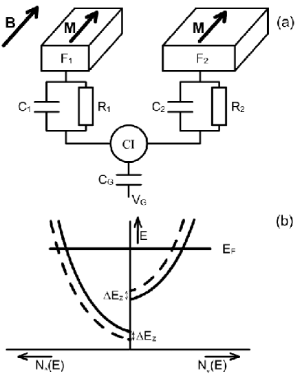
In this contribution, we consider a confined conductor weakly connected to
two ferromagnets, and (see Fig. 1a). The
coupling is described by two sets of resistances and capacitances,
, and , , respectively. Furthermore, the island
can be gated by a voltage via a capacitor . For a basic
introduction to the MCE, we first concentrate on one of the
ferromagnets only, , which is assumed magnetized in the
positive direction. Let us suppose that a positive external magnetic
field () is applied. In that case, the energy of the spin
up() and spin down() electrons shift by the
Zeeman energy, in opposite directions (see Fig. 1b).
However, for a ferromagnet, the density of states of both spin
species differs (). Hence, a shift in the
chemical potential needs to take place to keep the
number of electrons constant:ono
| (1) |
where the thermodynamic polarization P is defined as ,voetP is the gyromagnetic ratio and is the Bohr magneton. In practice, however, the ferromagnet will be attached to a macroscopic non-magnetic lead. This demands equal chemical potentials in both metals. Hence, the energy shift in the ferromagnet translates to a change in the contact potential between the ferromagnet and the normal metal, , according to, .ono Equivalently, one could say that the work function of the ferromagnet changes by . Since the ferromagnet is weakly coupled to the central island, this shift influences the Coulomb levels of the latter. In fact, an additional charge is induced onto the island due to the contact potential change . Applying a magnetic field thus has an effect that is similar to changing the gate voltage. This equivalence has been beautifully demonstrated by Ono et al.ono For the situation sketched above, we find:
| (2) |
Hence, if no magnetization rotation or switching takes place in the ferromagnet, the induced charge onto the island changes linearly with the applied field B. Interestingly, for a system in the coulomb blockade regime, the conductance G(q) is a (more or less periodic) function of the induced charge. Combining G(q) with eq. 2, we find that the conductance changes with field:
| (3) |
For a Coulomb island, can be calculated (or it can be
measured experimentally versus the gate voltage). The exact theory
to apply depends on the magnitude of the various energy scales
involved.kouwenhoven In any case, the sign of is
determined by the signs of both P and . Since the
function is periodic, and change
sign periodically, specifically at a Coulomb peak.
Next, we incorporate magnetization switching. Again, we start with
ferromagnet magnetized in the positive direction, but now we
ramp down the external field (). Then, according to eq.
3, the conductance changes linearly with B, as long as
the magnetization of the ferromagnet is unchanged. However, when B
reaches the coercive field, i.e., , the magnetization of
the ferromagnet switches to the negative direction. Hence, also
changes discontinuously, by . This results in a jump in the conductance via eq.
3. For more negative B fields, the conductance change
will be linear with B again, but now with opposite sign. So far,
we have considered an island connected to one ferromagnet only.
The extension to a spin valve device with two ferromagnetic
contacts is rather trivial, since their effects can be added.
Hence, a conductance change linear in B is expected,
with discontinuities at the coercive fields of both ferromagnets.
To illustrate the above, we consider the device in Fig.
1a), where and have different switching
fields. (This can be achieved by choosing thin strips of different
widths).johnson ; jedema ; tombros To calculate the conductance
properties of the system, i.e. , we make use of the orthodox
model of coulomb blockade.kouwenhoven ; voetCB This choice is
rather arbitrary, since eq. 3 can in principle be applied
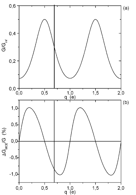
to other regimes of coulomb blockade. In Fig. 2a), we show
G vs for a certain choice of (symmetric) system parameters
(see caption Fig. 2).voetq From Fig. 2a)
and eq. 3, we infer that the sign and magnitude of the
MCE depend critically on two properties: i) the system parameters,
which define the sharpness of the Coulomb peaks; ii) the charge
state about which applies, which defines the distance
to a Coulomb peak. Close to the inflection point of sharp Coulomb
peaks, can become very large. Therefore, even a
small can induce a sizeable resistance change,
without a fundamental
limitation. In principle, effects exceeding are possible.
Next, we determine the field dependence of the conductance in the
system considered. We (arbitrarily) evaluate around the
charge state , where (indicated in Fig.
2). Furthermore, we use , which is the
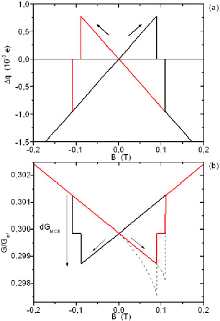
thermodynamic polarization of cobalt.ono ; voetP In Fig.
3a), we plot the induced charge on the island as a
function of magnetic field. Using eq. 3 together with Figs. 2a) and 3a) we obtain the field dependence of the conductance (see Fig. 3b). As discussed above, MCE gives
linear conductance changes for fields exceeding the switching
fields (giving a ’background magnetoconductance’ for large
fields). Around the switching fields, however, discontinuous
changes are seen which lead to hysteretic behavior. We note that
Fig. 3b) does show similarities with several experiments
in spin valve devicesvoetoffset . This emphasizes the
importance to separate both phenomena.tombros To connect to
experiment, we define the conductance change due to MCE, , as the sum of the two conductance steps at the coercive
fields, i.e., . We indicate in Fig.
3b). With this definition, we are able to plot the
relative magnetoconductance change as a
function of the charge state (see Fig. 2b)). Since this quantity is
proportional to the logarithmic derivative of the function ,
it changes sign at the extremes of Fig. 2a).voetoffset Figures 2 and 3 summarize the magnetoresistances that can be expected in
two-terminal spin valve structures, as a result of MCE.
Recently, much work has been done to investigate magnetic field
induced conductance changes in quantum dot-like structures, such
as carbon nanotubestsukagoshinat ; tsukagoshiapl ; sahooapl ; sahoonat ; kim ; chakraborty ; orgassa ; zhao ; alphenaar ; morpurgo and small metal
islands.yakushiji ; zhang . In these studies, conductance
changes are seen, which are generally interpreted in terms of spin
accumulation. However, three phenomena are noteworthy: 1) in many
cases, the change in conductance sets in before the magnetic field
changes sign, i.e. before the ferromagnetic electrodes switch
their magnetization. tsukagoshiapl ; tsukagoshinat ; sahooapl ; sahoonat ; nagabhirava ; yakushiji . 2) In some
studies the magnetoconductance changes sign as a function of gate
voltage.tsukagoshiapl ; sahoonat ; nagabhirava ; morpurgo 3) In
carbon nanotubes connected to only one ferromagnet (and to gold),
field-induced conductance changes are also observed.jensen
In the
latter system spin detection is clearly not possible.
We believe that in many experiments, MCE plays an important role.
As seen in Fig. 2, MCE-induced conductance changes have
the following properties: 1) they set in continuously at zero
field; 2) they change sign as a function of gate voltage, exactly
at the Coulomb peaks; 3) MCE-induced conductance changes also take
place for coulomb islands connected to only one ferromagnet, as
discussed above. Hence, the combination of MCE with spin
accumulation could be responsible for part of the phenomena listed
above. We note that the sign changes seen in
Refs.tsukagoshiapl ; sahoonat ; nagabhirava ; morpurgo have been
explained within (coherent) spin transport models (see also Ref. cottet ). However, in most of these systems coulomb blockade was also observed. This implies that MCE should be taken into account to obtain full correspondence between experiment and theory.
More generally, it is important to separate spin accumulation and MCE (and
other magnetoresistances) experimentally. The best way to do this, is by a direct measurement, using a non-local, four-probe geometrytombros .
This method separates out all magnetoresistances, not only MCE. If a
non-local measurement is not possible, the MCE and spin accumulation
should be separated in other ways. For example by monitoring the
temperature and gate voltage dependence of the relative conductance
changes and comparing these data sets to what is expected for MCE.
Clearly, the MCE decreases with a decrease of the conductance peaks.
Otherwise, experiments on nanotubes with two ferromagnetic contacts
can be compared to those with one ferromagnet and a normal
metal.sahoonat However, for a proper comparison, it is
essential, that the coupling to the normal metal and the ferromagnet
is very similar.
Finally, we discuss the influence of a demagnetizing field on the
MCE qualitatively. This field may play a significant role in
carbon nanotubes onto which a ferromagnetic strip is evaporated.
Locally, in the nanotube beneath the ferromagnet, the
demagnetizing field is expected to be quite high, of order 0.5 T
(assuming a field due to the ferromagnet of 1 T close to its
surface). The reason for this is that the aspect ratio of the
nanotube is unity (in the radial direction). The demagnetizing
field shifts the local work function of the ferromagnet thus
adding to MCE. Suppose now that the ferromagnet is magnetized in
the positive direction and a negative B field is applied. Then, we
expect the ferromagnetic domains in the vicinity of the nanotube
to change their orientation slowly. This locally rotates the
demagnetization field and therefore changes . As a
consequence, a characteristic magnetoconductance trace is
expected, with conductance changes setting in before the
ferromagnet actually switches (cf. Ref. brands ). As soon as
the ferromagnet does switch, we are in a mirror image of the
original situation and the contribution of the demagnetizing field
jumps back to its old value. We conclude that MCE due to the
demagnetizing field gives a continuous conductance change for
fields down to the coercive field. Just as for the
external-field-induced MCE, conductance changes are already
expected at fields close to 0 T. This is consistent with the
majority of two-terminal experiments.tsukagoshiapl ; tsukagoshinat ; sahooapl ; sahoonat ; nagabhirava ; yakushiji ; zhang In
Fig. 3b), we sketch the total MCE, including that of the
demagnitizing field (dashed line). We note the similarity of the
full MCE curve (though partly qualitative) with what is expected
for spin accumulation.voetsym
In summary, we show that the magnetocoulomb effect should be taken
into account to explain experiments on spin valve structures in the
coulomb blockade regime. A proper separation of spin accumulation
and MCE is essential for a good understanding of the first.
Acknowledgements This work was financed by the Nederlandse Organisatie voor Wetenschappelijk Onderzoek, NWO, via a Pionier grant.
References
- (1) K. Tsukagoshi, B. W. Alphenaar and H. Ago, Nature, 401 572 (1999).
- (2) K. Tsukagoshi and B. W. Alphenaar, Superlattices and Microstructures 27, 565 (2000).
- (3) S. Sahoo, T. Kontos, C. Schönenberger and C. Sürgers, Appl. Phys. Lett. 86, 112109 (2005)
- (4) S. Sahoo, T. Kontos, J. Furer, C. Hoffmann, M. Grber, A. Cottet and C Schönenberger, Nature Physics (2005)
- (5) K. Yakushiji, F. Ernult, H. Imamura, K. Yamane, S. Mitani, K. Takanashi, S. Takahashi, S. Maekawa and H. Fujimori. Nature 4, 57 (2005)
- (6) L.J. Zhang, C. Y. Wang, Y. G. Wei, X. Y. Liu, and D. Davidovic Phys. Rev. B 72, 155445 (2005)
- (7) J. R. Kim, H. M. So, J.J Kim and J. Kim, Phys. Rev. B. 66, 233401 (2002).
- (8) S. Chakraborty, K. M. Walsh, L. Liu, K. Tsukagoshi and B. W. Alphenaar, App. Phys. Lett 83, 1008 (2003).
- (9) D. Orgassa, G. J. Mankey and H. Fujiwara, Nanotechnology, 12, 281 (2001).
- (10) B. Zhao, I. Mönch, T. Mühl, H. Vinzelberg, and C. M. Schneider , J. Appl. Phys. 91, 7026 (2002)
- (11) B.W. Alphenaar, S. Chakraborty and K. Tsukagoshi, in Electron Transport in Quantum Dots (Kluwer Academic/Plenum Publishers, New York 2003) chap. 11.
- (12) K. Ono, H. Shimada and Y. Ootuka, J. Phys. Soc. Jpn 67, 2852 (1998); H. Shimada, K. Ono, and Y. Ootuka, J. Appl. Phys. 93(10), 8259 (2003), H. Shimada and Y. Ootuka, Phys. Rev. B 64, 235418 (2001)
- (13) For MCE one should consider the thermodynamic quantity P, i.e., P as a result of the full band structure. This P differs considerably from the polarization determined in tunnel experiments, since for the latter tunnel matrix elements play a role as well. For Co, , whereas for Ni, . See Ref. ono .
- (14) L.P. Kouwenhoven et al. Electron transport in quantum dots, Proc. Adv. Study Institute on Mesoscopic Electron transport (L.L. Sohn, L.P. Kouwenhoven and G. Sch n, Eds), Kluwer 1997
- (15) M. Johnson and R.H. Silsbee, Phys. Rev. Lett. 55, 1790 (1985)
- (16) F.J. Jedema, A. T. Filip and B. J. van Wees, Nature 410, 345 (2001).
- (17) N. Tombros, S.J. van der Molen and B.J. van Wees, cond-mat/0506538
- (18) We assume each coulomb peak to be independent. Although this is not exactly correct, it suffices to show the principle of MCE.
- (19) We use q as a relative quantity, i.e., corresponds to a situation where N electrons are present on the island (charge ). N depends on the properties of the system and can be large. A change in q by e corresponds to a change in coulomb level energy by (where is the total capacitance of the island).
- (20) We note that Fig. 2b) changes considerably for a sample which exhibits a non-zero background conductance.
- (21) H.T. Man, L.J.W. Wever and A.F. Morpurgo, Cond-mat/0512505 v1
- (22) B. Nagabhirava, T. Bansal, G. Suanasekera, L. Liu, and B.W. Alphenaar, preprint, cond-mat/0510112
- (23) A. Jensen, J.R. Hauptmann, J. Nygard, and P.E. Lindelof, Phys. Rev. B 72, 035419 (2005)
- (24) A. Cottet, T. Kontos, W. Belzig, C. Schönenberger and C. Bruder, preprint, cond-mat/0512176 v1
- (25) M. Brands and G. Dumpich J. Appl. Phys. 97, 114311 (2005)
- (26) We choose a symmetric configuration. However, if asymmetric contacts are assumed (e.g., ), the shape of Fig. 2b) will change accordingly. If one of the peaks in Fig.2b) dominates the other, only one peak may be observed experimentally.