Granular Flows in a Rotating Drum: the Scaling Law between Velocity and Thickness of the Flow
Abstract
The flow of dry granular material in a half-filled rotating drum is studied. The thickness of the flowing zone is measured for several rotation speeds, drum sizes and beads sizes (size ratio between drum and beads ranging from 47 to 7400). Varying the rotation speed, a scaling law linking mean velocity vs thickness of the flow, , is deduced for each couple (beads, drum). The obtained exponent is not always equal to 1, value previously reported in a drum, but varies with the geometry of the system. For small size ratios, exponents higher than 1 are obtained due to a saturation of the flowing zone thickness. The exponent of the power law decreases with the size ratio, leading to exponents lower than 1 for high size ratios. These exponents imply that the velocity gradient of a dry granular flow in a rotating drum is not constant. More fundamentally, these results show that the flow of a granular material in a rotating drum is very sensible to the geometry, and that the deduction of the “rheology” of a granular medium flowing in such a geometry is not obvious.
pacs:
45.50.-jDynamics and kinematics of a particle and a system of particles and 45.70.-nGranular systemsResearch in granular material has received a renewed interest these last years OttinoKhakhar01 . Nevertheless, mechanisms governing flows of particles are not yet completely understood. For example, two scaling laws “mean velocity vs flowing zone thickness ” have been proposed. For flows down a rough inclined plane, Pouliquen Pouliquen99 and Azanza et al. Azanza99 have obtained while Rajchenbach Rajchenbach00 , Bonamy et al. BonamyDaviaud02 and GDR MiDi GDRMiDi report a linear and constant (with the rotation speed) velocity gradient in a rotating drum, inducing a scaling law . Recently, Ancey AnceyPRE02 found, for the flow down an incline, an exponent in the scaling law that is not constant, but presents 2 different values, characteristic of 2 distinct regimes: for high slopes, is around 1 to 2 (values that are compatible with , but also with ), but for gentle slopes 0, which gives the surprising result that the mean velocity of the flow is constant (independent of the thickness of the flowing layer). Except the curvature of the flowing layer, the main difference between these systems is that on a rough inclined plane, the active layer flows down a substratum made of glued particles, while in a rotating drum, the substratum, made of loose particles, continuously exchanges particles with the flowing zone. The incline with a gentle slope is an intermediate case between a rotating drum and a flow down a rough inclined plane since a static bed can form in the basal part. The incompatibility between these scaling laws leads to the development of theoretical models of granular flows that have to consider each case independently AradianRaphael00 . Another incompatibility appears if we consider the work of Parker et al. ParkerDijkstra97 who report that in a drum, the thickness of the flowing layer is constant with the rotation speed . Orpe and Khakhar also studied the flow of a dry granular material in a rotating drum OrpeKhakhar01 . In their study, they did not directly extract a scaling law connecting velocity and thickness of the flowing layer. But they measured that the velocity gradient depends on the angle of the free surface (, where is the angle of repose) and that increases linearly with the rotation speed (). From these two relations, and assuming that the angle difference remains small (), one easily deduces the scaling law . This result is intermediate between a constant velocity gradient, associated to the scaling Rajchenbach00 ; BonamyDaviaud02 and a constant thickness of the flowing layer ParkerDijkstra97 in a rotating drum.
The work presented here reconsiders the problem of the scaling law vs in a rotating drum. More precisely, the questions we address to are: is there a scaling law connecting thickness and velocity of the flow in a rotating drum ? Is the exponent unique, or does it depends on the geometry ? For “large drums”, do we expect the same exponent as for a rough incline plane whose curvature is infinite ? To answer these questions, a large number of drums, sizes of beads and rotation speeds are studied. Indeed, in previous work Rajchenbach00 ; BonamyDaviaud02 ; ParkerDijkstra97 ; OrpeKhakhar01 , the ratio diameter of the drum over diameter of the beads is always inferior to 400. In this work, the ratio varies from 47 to 7400, while the rotation speed ranges from 2 to 25 rpm. In our experiments, we measure the thickness of the flowing layer versus the rotation speed . To obtain the link between the power law and the law that is deduced from our experiments, we use the definition of the flow rate where is the mean velocity of the flow, and note that the flux entering the flowing layer in a half-filled rotating drum is given by Rajchenbach00 where is the drum radius. Here is assumed small compared to hsmall and the previous relation is simplified in . One easily obtains . Thus, the scaling law previously reported, , corresponds to with .
1 Experimental apparatus
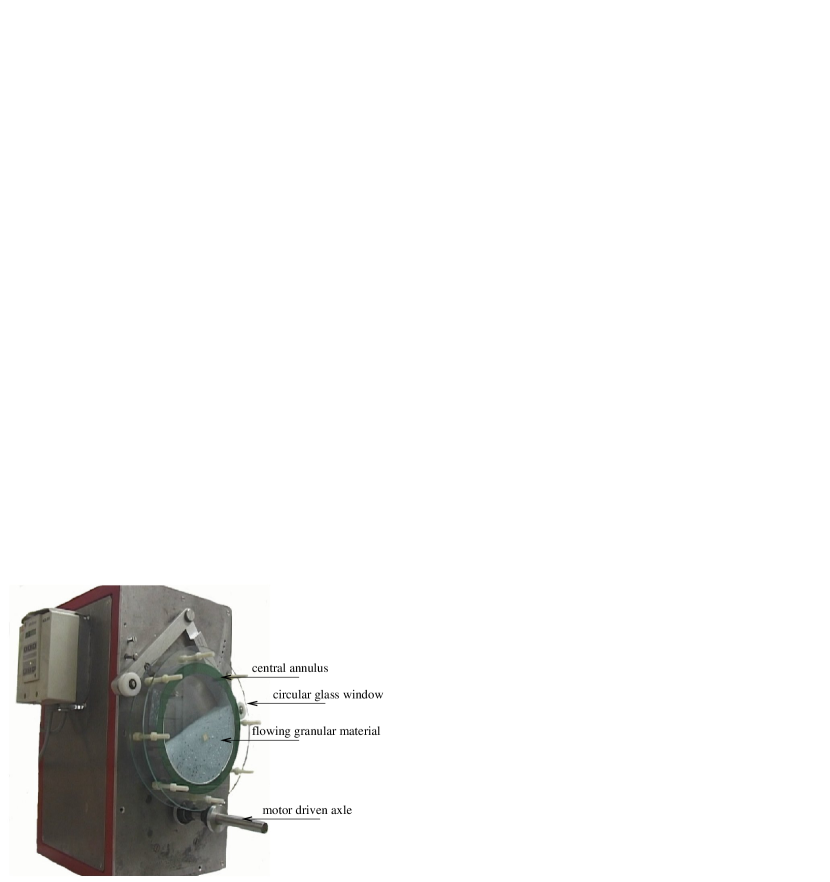
The drum is composed of an annulus of diameter (5.6, 12, 20, 30 and 50 cm) and width (0.6, 1, 2, 3, 4, and 6 cm), held between two circular glass windows, and placed vertically on a rotating axle driven by a continuous current motor (figure 1). The rotation speed of the drum varies from 2 to 25 rpm in order to be in the rolling regime (continuous flow regime). The drum is half-filled with glass beads of mean diameter , ranging from 0.07 mm to 2 mm, with a density of 2.5 g/cm3. The studied size ratios (and mean beads diameter) are: = 47 ( = 1.2 mm), 100 (560 m, 1.2 mm, 2 mm), 166 (1.2 mm), 214 (560 m), 357 (560 m), 600 (200 m), 895 (335 m), 1000 (200 m), 1500 (200 m), 2500 (200 m) and 7400 (75 m). The case in which 45-90 m glass beads are used (ratio = 7400) has to be considered with care. The corresponding results are reported since they are compatible with the others. The humidity is held between 50% and 55% in order to reduce electrostatic effects or capillary bridges between fine particles Fraysse99 . Experiments are filmed with a CCD camera whose shutter speed is chosen in order to follow particle trajectories (long exposure time). This is analogous to the technique reported in Orpe and Khakhar OrpeKhakhar01 . Thus the particles at the lowest point of the base of the flowing zone appear to be at rest on the film, defining a static point in the laboratory frame reference. is the distance measured between the static point and the free surface, perpendicularly to this surface. In fact, one would like to measure a static point in the drum frame reference. But we will see that in the flow, the velocity decreases rapidly to zero and reconnects with a plastic deformation zone. Thus there is no static point in the drum frame reference. There are 2 possibilities to define a flowing layer: to assume a linear velocity profile to calculate a point where the velocity is equal to 0 in the drum frame reference GwenThese , or to take the static point in the laboratory frame reference. The distance between these 2 points is very small and the choice does not affect the values of the results (thicknesses of the flowing layer, velocity profiles and exponents of the scaling laws). In the following, we present the results obtained in the laboratory frame reference since they are directly measured in the experiment, with no assumed hypothesis.
For each experiment, measurements are reproduced between 10 and 20 times, which allows to represent mean data with error bars using the Student test with a 95% interval of confidence (standard deviation and number of measurements are taken into account in the error bars).
The possible influence of several parameters has been considered: the precision of the filling of the drum (47.5, 50 and 53.5%), the size distribution of the particles, the width of the drum ( = 20 cm, = 2 mm, 0.5, 1, 2, 4, 6 cm) and the influence of the experimenter in the measurement of the static point (4 different experimenters). In all the cases, the discrepancy in the measurements is not statistically significant GwenThese . Finally, we are aware of the fact that all measurements are made through a lateral window, but several experimental works suggest that the thickness of the flowing zone at the wall is not, or only slightly, modified compared to those at the center, even if the velocity is reduced at the wall OrpeKhakhar01 ; GwenThese ; ChevoirProchnow01 ; BoatengBarr97 ; TaberletRichard03

2 Results: Thickness of the flowing zone
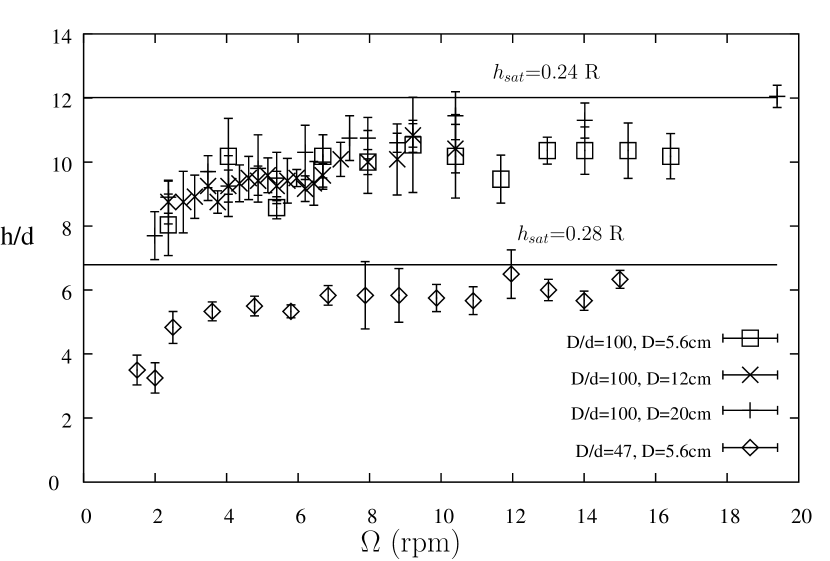
Figure 2 presents the thickness of the flowing zone (measured in bead diameters ) versus the rotation speed. The curves organise in raising ratios . For clarity reasons, all the studied ratios are not reported on the graph, even if they all show the same behaviour GwenThese .
One may note that for low size ratios (typically ), the thickness of the flow is close to a 10-beads layer. Even if this value is frequently reported, figure 2 shows that this size of the flowing layer is not universal but depends on the ratio. In our experiments, the thickness of the flow ranges from 4 to 200 beads.
Special attention was put into homothetic systems, i.e. systems with equal size ratios, to check that and are the relevant parameters. For these homothetic systems ( = 100, = 20 and = 5.6, 12, 20 cm), all the curves superimpose within the error bars (figure 3). This has already been reported in GwenThese ; GwenPowdGrains while studying the angle of avalanches, of repose and of continuous flow. This can also be observed on figure 2 for close ratios ( = 895, = 30 cm and = 1000, 20 cm). This result suggests that the Froude number, Fr= with and the gravity acceleration, is not the relevant parameter to describe the thickness of the flowing zone. Indeed, in the cases = 895 and = 1000, if the thickness is plotted versus Froude number, the curves do not superimpose as precisely as in figure 2.
The flowing layer thickness curves presented on figure 2 show two different behaviors: for low ratios , the flowing zone increases and rapidly reaches a constant flowing thickness (saturation thickness). Parker et al. ParkerDijkstra97 report a saturation thickness corresponding in average to 35% of the radius of the drum (but with large variations), with size ratios ranging from = 33 to 90. Figure 3 shows that in our experiments, the saturation thickness is around 28% (resp. 24%) of the radius of the drum for a size ratio = 47 (resp. = 100). For higher ratios, the flowing layer thickness increases continuously with the rotation speed . For these size ratios, one expects that would stop increasing when a saturation thickness will be reached. But we assume this would occur for rotation speeds high enough such that other phenomena might have already appeared: strong “S” shaped free surface, cataracting and eventually centrifugation.
3 Saturation regime
In the saturated regime, the thickness of the flow remains almost constant when increases, as previously observed ParkerDijkstra97 . The increase of the flow rate is mainly adapted by an increase of the mean velocity. We deduced that, in this regime, the velocity gradient cannot be constant, and should increase with the rotation speed.
As this deduction is indirect and concerns a gradient averaged on the whole flowing layer, 4 velocity profiles have been measured along an axis () perpendicular to the free surface (defining the axis). This will allow us to compare velocity profiles and their associated scaling law with the one obtained by previous authors Rajchenbach00 ; BonamyDaviaud02 . A high speed camera (800 fps) have been used. The shift of one particle between two frames is about a few bead diameters. Thus, we reject the idea of using a particle image velocimetry software. Instead, we follow the trajectories of a few colored glass beads, selecting them “by hand” on a specially dedicated software.
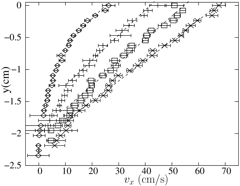

Figure 4 shows velocity profiles measured for rotation speeds of 4, 9.2, 14, 19.4 rpm ( 100, 20 cm). Between 630 and 1200 velocities have been measured for each of the four profiles. As pointed out by Komatsu et al. KomatsuInagasaki01 , the profiles display a linear part and an exponential part (reconnection with the static zone). For the 3 higher rotation speeds (figure 4), we can clearly see a linear part in the velocity profiles, while for the 4 rpm case, the overall profile seems convex.
The increase of the total velocity gradient can be induced by two effects: an increase of the slope of the linear part, and also an increase of the extension of this linear part, and thus a decrease of the reconnection zone thickness.
From figure 4, we see that the linear part increases strongly between rpm and rpm and this contributes to an increase of the total velocity gradient of the flowing layer. We will now focus on the linear part, and see if it presents a constant velocity gradient as previously reported Rajchenbach00 ; BonamyDaviaud02 . Although the linear part is not obvious for the 4 rpm case, velocity gradients are obtained by fitting the upper part (dashed lines) of the velocity profiles. The obtained velocity gradients are not equal ( = 24.2, 25.5, 27.7, 31.5 s-1), but increase with the rotation speed.
As a fit of the linear part might be subject to discussion (especially the frontier between the linear part and the exponential reconnection is rather subjective), we have decided to perform numerical simulations with a geometry close to the experimental conditions: 4300 disks of 2 mm diameter flowing in a 2D drum of 20 cm diameter. The numerical method is a distinct element method, with a linear spring dash-pot model for the normal forces and the Cundal and Strack scheme for the tangential forces (see for example DippelWolf96 ). More details on the numerical simulations will be given elsewhere DOrtona05 . Four rotation speeds are simulated = 5, 10, 15 and 20 rpm. The linear part and the exponential reconnection with the static part appear more clearly (figure 5), and the measured velocity gradient does not depend on the frontier with the reconnection zone (while remaining in the dashed lines region). Again, the extension of the linear part increases with the rotation speed . Moreover, the velocity gradients obtained by fitting the linear part increase with the rotation speed (resp. 8.23, 10.57, 12.61 and 14.63 s-1). The values obtained in the simulation are different from the experiment, probably due to the fact that the simulations are in two dimensions.
We see that, in both cases (experiment or simulation), the velocity gradients taken on the whole layer, including the reconnection zone (global), or taken on the linear part of the profile (local) are not constant and increase with the rotation speed. Thus, if a scaling law is used to fit our data on velocity and flowing thickness, the exponent would be superior to 1.
4 Velocity scaling laws
From our experiments, we deduce scaling laws between the thickness of the flowing zone and the rotation speed . We then derive scaling laws connecting thickness of the flowing layer and mean velocity and compare with the results obtained by previous authors.

Figure 6 shows the experimental data for several values of in a log-log plot and crude fits using a power law with a least square method. When a power law is used to fit these data, very good regressions are obtained. We found that the obtained exponent is not unique, and depends on the ratio. Table 1 gives the exponents obtained by fitting vs and the corresponding power law . For the small ratios , the exponents are much larger than 1, which is in accordance with the increase of the global velocity gradient with (fig. 4). For example, the power law for the ratio = 100 is , and induces a “pseudo” scaling never reported before. When the size ratio increases, this exponent continuously decreases, with values inferior to 1 for the 3 cases = 1500, 2500 and 7400.
For small size ratios (), to fit the data using a power law might seem not logical since we just shown that a saturation thickness is expected for high rotation speeds. A function with an asymptotic behavior should be a better choice. Our aim here is simply to show that the existence of a saturation thickness does not appear through a sharp transition in the curves: the saturation process happens progressively, affecting the thickness of the flow even for low rotation speeds. For larger size ratios, this saturation process probably also influences the thickness of the flow, even if the saturation thickness is not reached. Indeed, figure 6 shows that the slopes continuously increase. These fits show that if a universal power law between and (or and ) exists in a rotating drum, it can not be obtained for small size ratios, but only in systems with a flowing zone thickness small compared to the saturation thickness. One solution might be to use low rotation speeds to get thin flowing layers. Unfortunately, the system reaches the avalanching regime, and the flow is no longer continuous. The other solution is to study high size ratios, expecting that the exponent would reach an asymptotic value. But in our experiments, no asymptotic value is obtained. When increasing the size ratio, the exponent decreases continuously, taking values close to 1 for size ratio between 1000 and 1500, and values lower than 1 for our larger size ratios (see figure 7 and table 1).

| 47 | 0.170.03 | 5.21.2 |
|---|---|---|
| 100 | 0.150.011 | 5.50.5 |
| 166 | 0.220.03 | 3.60.6 |
| 214 | 0.250.03 | 3.00.4 |
| 357 | 0.300.03 | 2.40.3 |
| 600 | 0.280.02 | 2.50.2 |
| 895 | 0.4490.013 | 1.230.06 |
| 1000 | 0.370.03 | 1.70.2 |
| 1500 | 0.560.02 | 0.790.06 |
| 2500 | 0.640.02 | 0.570.05 |
| 7400 | 0.680.06 | 0.480.14 |

An exponent lower than 1 induces a decrease of the global velocity gradient when rotation speed increases. This result is opposite to what is observed for small size ratios. To confirm this counter-intuitive evolution, direct velocity profiles measurements were performed. The system = 1500 was chosen as a compromise between the feasibility of measurement (the particles are still distinguishable) and a power law with an exponent smaller than 1. Figure 8 shows velocity profiles with the associated error bars. The error bars are smaller than on figure 4 because between 2500 and 4100 particle displacements have been measured for each profile. This was necessary to reduce the error in the velocity gradient estimation, and to have statistically significant differences in the slope of the profiles. Again the linear part growths. But, this time, the evolution of the reconnection zone is not clear. Thus we cannot explain the obtained power law only by these two evolutions. On the other hand, the velocity gradients in the linear part have been measured slightly decreasing with which is compatible with a power law inferior to 1. In both cases (figure 6 and 8), the global velocity gradients deduced from the power law and the local gradients measured on the linear part of the profiles evolve jointly.
5 Discussion
These experiments have shown that both global and local velocity gradients of a granular flow in a rotating drum are not constant with the rotation speed. The variation of the local velocity gradient is new compared to results reported before Rajchenbach00 ; BonamyDaviaud02 , even if an increase of the velocity gradient for high rotation speed is also suggested by the data (Fig. 20) of Orpe and Khakhar OrpeKhakhar01 . Our results induce that the scaling law is not universal in a drum but that the value of in depends on the size ratio between drum and beads. In our experiments, the peculiar power law should be obtained for a size ratio comprised between 1000 and 1500. In their experiments, Rajchenbach Rajchenbach00 and Bonamy et al. BonamyDaviaud02 have obtained this scaling for size ratios around 150. The difference is probably due to the fact that Rajchenbach reports the use of steel beads in a 2D system, while Bonamy et al. have used steel and glass beads, but in a quasi 2D system. We also note that our scaling laws are obtained with the measurement of the thickness of the flow including a part of the reconnection zone while Rajchenbach and Bonamy et al. found that the velocity gradient of the linear part is constant.
Recently, Taberlet et. al. TaberletRichard03 show that the thickness of the flowing layer of a heap in a thin channel is imposed by the channel width. Jop et. al. JopForterre05 also show that side walls control the steady flow on pile for channel width ranging from 20 to 600 particle diameters. But in our experiments, the width can not determine the thickness of the flowing layer since it was shown that changing the width of the drum does not affect the thickness of the flowing zone GwenThese . In our system, the thickness of the flowing layer is mainly imposed by the size ratio (diameter of the drum on diameter of the beads) and by the rotation speed (probably due to the saturation process).
6 Conclusions
The flow of dry granular material (diameter ) in a rotating drum (diameter ) with size ratios ranging from 47 to 7400 is studied. The thickness of the flowing layer is measured for increasing rotation speeds . Experimental curves corresponding to the same ratio coincide suggesting that this ratio is the leading parameter (with the rotation speed) imposing the thickness of the flowing zone in a rotating drum.
For small size ratios, a saturation thickness, previously reported in literature, is observed, inducing a thickness of the flowing zone constant with the rotation speed, and thus a velocity gradient increasing with the rotation speed.
If a power law is deduced from these experiments, the exponent is not constant as previously reported, but varies from 5 (small size ratios) to 0.5 (larger size ratios). An exponent smaller (resp. larger) than 1 induces a decrease (resp. increase) of the velocity gradient while the rotation speed increases. This has been confirmed by direct measurements of the velocity profile.
We also see that for large size ratios, the exponent does not tend to the value obtained for a flow down a rough incline plane: . This shows that the two systems, flow down an incline and rotating drum, are fundamentally different. The difference is probably due to the presence or not of a static bed of beads. The question that remains to be answered is: when increasing the size ratio (), does the exponent of the scaling law tends to 0 like observed by Ancey AnceyPRE02 for a flow on an incline with a basal static bed, or to some non null value, like , as suggested by data in our larger system = 7400 ?
Acknowledgements.
We wish to acknowledge Gérard Verdier for his image processing software and Nathalie Thomas for interesting discussions and careful reading of this article.References
- (1) J.M. Ottino, D.V. Khakhar, Fundamental research in heaping, mixing and segregation of granular materials: challenges and perspectives, Powder Technol. 121 (2001) 117-22
- (2) O. Pouliquen, Scaling laws in granular flows down rough inclined planes, Phys. Fluids 11 3 (1999) 542-8
- (3) E. Azanza, F. Chevoir, P. Mourcheront, Experimental study of collisional granular flows down an inclined plane, J. Fluid Mech. 400 10 (1999) 199-227
- (4) J. Rajchenbach, Granular flows, Advances in Physics 49 2 (2000) 229-56; J. Rajchenbach, Flow in powders: from discrete avalanches to continuous regime, Phys. Rev. Lett. 65 18 (1990) 2221-4
- (5) D. Bonamy, F. Daviaud, L. Laurent, Experimental study of granular surface flows via a fast camera: a continuous description, Phys. Fluids 14 5 (2002) 1666-73
- (6) GDR MiDi, On dense granular flows, Eur. Phys. J. E 14 (2004) 341-365
- (7) C. Ancey, Dry granular flows down an inclined channel: Experimental investigations on the frictional-collisional regime, Phys. Rev. E 65 (2002) 11304
- (8) A. Aradian, E. Raphael, P.G. de Gennes, Thick surface flows of granular materials: the effect of velocity profile on the avalanche amplitude, Phys. Rev. E 60 2 (1999) 2009-19
- (9) D.J. Parker, A.E. Dijkstra, T.W. Martin, J.P.K. Seville, Positron emission particle tracking studies of spherical particle motion in rotating drums, Chem. Eng. Sci. 52 (1997) 2011-22
- (10) A. Orpe, D.V. Khakhar, Scaling relations for granular flow in quasi-2d rotating cylinders, Phys. Rev. E 64 3 (2001) 105-16
- (11) Taking into account the thickness of flowing layer while deducing the exponent requires the fit of the mean velocity data that are not directly measured, and thus present a larger dispersion GwenThese . The exponents obtained by this method are close to those presented in table 1.
- (12) N. Fraysse, H. Thomé, L. Petit, Humidity effects on the stability of a sandpile, Eur. Phys. J. B 11 (1999) 615-9
- (13) Gwenaëlle Félix, Écoulement de milieux granulaires en tambour tournant : Étude de quelques transitions de régime, application à la ségrégation, Ph.D. Thesis from Institut National Polytechnique de Lorraine, France, November 22, 2002 (in french)
- (14) F. Chevoir, M. Prochnow, P. Moucheront, F. Da Cruz, Dense granular flows in a vertical chute, Powder and Grains 2001, Kishino Ed., Swets & Zeitlinger, Lisse, 2001
- (15) A.A. Boateng, P.V Barr, Granular flow behabiour in the transverse plane of a partially filled rotating cylinder, J. Fluid Mech. 330 (1997) 233-49
- (16) N. Taberlet, P. Richard, A. Valance, W. Losert, J. M. Pasini, J. T. Jenkins, R. Delannay, Superstable Granular Heap in a Thin Channel, Phys. Rev. Lett. 91, 264301
- (17) G. Félix, V. Falk, U. D’Ortona, Avalanches of dry granular material in rotating drums, Powder and Grains 2001, Kishino Ed., Swets & Zeitlinger, Lisse, 2001
- (18) T.S. Komatsu, S. Inagasaki, N. Nakagawa, S. Nasuno, Creep motion in a granular pile exhibiting steady surface flow, Phys. Rev. Lett. 86 9 (2001) 1757-60
- (19) J. Schäffer, S. Dippel, D.E. Wolf, Force schemes in simulations of granular materials, J. Phys. I France 6 (1996) 5-20
- (20) U. D’Ortona, Numerical simulation of granular flows down rough inclines, in preparation
- (21) P. Jop, Y. Forterre, O. Pouliquen, Crucial role of sidewalls in granular surface flows: consequences for the rheology, J. Fluid Mech. 541 (2005) 167-92