Magnetic order and valency at La0.7Sr0.3MnO3/SrTiO3 interfaces
Abstract
We report on first principles calculations of the electronic structure of La0.7Sr0.3MnO3/SrTiO3 junction with two possible types of interface terminations. We find that the La0.7Sr0.3O/TiO2 interface preserves the interlayer ferromagnetic coupling between the interface MnO2 layer and the bulk. The other interface, MnO2/SrO, favours antiferromagnetic coupling with the bulk. By inserting two unit cells of undoped LaMnO3 at the interface the ferromagnetism is recovered. This is understood in terms of the doping level and the mobility of carriers near the interface.
Spintronic devices use the information carried by the spin of electrons as well as their charge, and spin dependent tunnelling lies at the heart of their operation. They depend on having a strongly polarised or half metallic ferromagnet from which polarised carriers can tunnel. The rare earth manganites, particularly La0.7Sr0.3MnO3 (LSMO), are good candidates for tunnel devices because there is evidence that they have a high polarisation park98 ; nadgorny01 . There are three factors that should be considered for a good tunnelling device. First the magnetism of the surface layer should not be much lower than the bulk, second the electronic spin polarisation, , at the surface should be high, and third if the velocities of the majority carriers should be high and that of the minority carriers should be low mazin99 . A perfect tunneling magnetoresistance (TMR) would be obtained if the minority spin states at the interface were actually localised.
Insulating SrTiO3 (STO) is one of the most promising materials to use as a tunnel barrier. It is a good lattice match to LSMO and also has a small band gap so that the tunnelling rates are high. Hence the importance of understanding the nature of the interface between these two perovskites. The usual surface of STO is a TiO2 layer izumi98 . If a film of LSMO is deposited on top, it will normally contain an equal number of La0.7Sr0.3O and MnO2 layers and so will be terminated by a MnO2 layer izumi98 . A tunnel barrier of STO will thus start with a SrO layer and finish with a TiO2 layer so that junctions(interfaces) of both types occur.
There have recently been studies samet03 ; bowen03 ; bowenthesis ; yamada04 ; izumi01 ; izumi02 of the magnetic properties of LSMO/STO interface when it is grown as La0.7Sr0.3O/TiO2 and as MnO2/SrO. It is convenient to refer to these as TiO2 and SrO interfaces respectively. Bowen et al. bowen03 ; bowenthesis grew tunnel structures in which both interfaces were of the TiO2 type and obtained a value of the tunnelling magnetoresistance (TMR) of 1800%. Yamada et al. yamada04 showed that the magnetism and TMR at the SrO interface were enhanced when two layers of undoped LaO were grown adjacent to the SrO layer, however even then the magnitude of the observed TMR (170%) is far below what was observed for the TiO2 interface.
In this letter we give the first microscopic analysis of the nature of the magnetism for LSMO at a TiO2 and at a SrO interface, when zero, one and two layers of undoped LMO are grown adjacent to the interface . We address the three important issues: the magnitude of the magnetic exchange between the surface layer and the bulk, the density of states at the Fermi level both in the bulk and at the surface and the value of the spin polarisation, , at the surface and finally the relative mobility of the majority and minority carriers at the surface.
We address all the terminations in a self-consistent Self-Interaction Corrected LSD (SIC-LSD) temmerman calculation by means of sufficiently large supercells (8-10 unit cells of LSMO and 8 unit cells of STO). The SIC-LSD method has been applied successfully to a variety of problems where competition occurs between localisation and delocalisation of electrons in “strongly” correlated systems such as transition metal oxides szotek93 .
In the present study we have used the experimental lattice parameter of SrTiO3, 7.38 a.u, for the whole system which has a cubic perovskite structure. To model the LSMO system we use a virtual La atom of atomic number , where is the doping level. This approximation is very reasonable in this case which has been confirmed by comparison to supercell calculations banach .
We first apply our method to calculating the electronic structure for bulk LSMO and STO. We find LSMO to be nearly half-metallic with the Fermi level () lying at the bottom of the minority conduction band as shown on Fig. 1. In the ground state the three orbits are localised and the total magnetic moment in the unit cell is of 3.47 (experimental moment is ). Note that in a half-metal the total moment should be 3.70. There has been much debate on whether the manganites such as LSMO are really half-metals. Spin-polarised photoemission spectroscopy measurements on LSMO showed a 100% park98 spin polarisation at while Andreev reflection experiment nadgorny01 found existence of minority states at . Early LSD calculations found the system to be nearly half-metallic livesay99 and recently using SIC and allowing for mixed valency this material has been established to be half-metallic banach . It was argued pickett96 that in manganites, like LSMO, the minority electrons localise because of the random distribution of the trivalent and divalent ions as well as their narrow occupied bandwidth (Fig. 1). Consequently, the system behaves as a transport half-metal mazin99 .
Bulk STO is known to be a band insulator and in our LDA calculation we find that it has a gap of 2.09eV, smaller than its experimental value of 3.25eV. The LDA is well-known to underestimate band-gaps and one way to remedy this deficiency would be to use a GW godby88 approximation. There is no SI correction in this system because there are no localised electrons, the Ti ion being in the configuration.
We have considered both interface terminations (TiO2 and SrO) by performing two separate calculations with symmetric supercells so that in each case we have only one kind of termination present. Using the following notation: L for La0.7Sr0.3O, M for MnO2, T for TiO2 and S for SrO, the first supercell is LM[LM]6LT[ST]6ST which has two TiO2-type interfaces. The second is M[LM]6LMST[ST]6S which has two SrO-type interfaces. The subscript is for the number of formula units. We also consider the cases where one and two La0.7Sr0.3O layers at the SrO interface are replaced by undoped LaO . Within the layers we have assumed ferromagnetic (FM) coupling and therefore used one Mn atom per layer. This is a very reasonable assumption since both ( and ) orbits have significant hopping integrals within the layers and it is known from the double-exchange model that the kinetic energy mediates the FM coupling. Between the layers, on the other hand, only the - hopping integral is nonzero, and this has significant influence on the interlayer magnetic coupling zenia . Bulk LSMO is ferromagnetic so we investigate the magnitude of the exchange interaction between the surface layer and the bulk by considering the energy difference of the supercell between when the interface MnO2 layer is ferromagnetically (FM) and antiferromagnetically (AF) aligned with the bulk and compare this to the bulk value. Experimentally, this is corresponds to the differences observed between the interface and bulk Curie temperatures () garcia04 . We find that the exchange estimated in this way depends on the interface.
| Bulk | TiO2 | SrO | SrO + 1 LaO | SrO + 2 LaO | |
|---|---|---|---|---|---|
| 6.0 | 3.5 | -6.3 | -5.5 | 3.0 | |
| Moment | 3.47 | 3.21 | 3.31 | 3.34 | 3.31 |
The values of the exchange energies are given in the Table 1. In the case of TiO2 interfaces we find a value of the surface exchange which is 58% of the bulk value indicating that the surface magnetism is well coupled to the bulk. However for SrO interfaces we find that is negative, indicating that the surface layer is coupled antiferromagnetically to the bulk, this is clearly not a good candidate for a large TMR. The magnitude of the antiferromagnetic coupling is reduced if one undoped layer of LaO is inserted as the penultimate layer to the interface. However the coupling becomes ferromagnetic when two layers of undoped LaMnO are grown next to the surface. This is the configuration that Yamada et al yamada04 found gave better tunnelling magnetoresistance. In this case the value of is 50% that of the bulk indicating that the surface magnetism is comparable to that of the TiO2 interface.
| Coupling at interface | SIC correction | TiO2 | SrO |
|---|---|---|---|
| FM | 0.0 | 0.0 | |
| FM | 12.9 | 39.8 | |
| FM | 23.5 | 37.9 | |
| AF | 3.5 | -6.3 | |
| AF | 8.9 | 46.0 | |
| AF | 22.4 | 30.6 |
The SIC calculations indicate that it is favourable if only the states are localised. However we can infer from the results presented in Table 2 that the energy required to localise a further electron depends on the symmetry of the electron state, the magnetisation and the nature of the interface. We have a qualitative understanding of these effect from the fact that it is only the electrons in the orbits that transfer between layers. In the case of the TiO interface localising this orbit will switch off some of the ferromagnetic coupling and hence this has a higher penalty for the FM state than for the AF state, for this interface there is a larger penalty to localise the state so indicating that in the conducting state the occupation of this state is lower than for as was found to be favourable for ferromagnetic coupling zenia . All the localisation energies for the states are higher for the SrO interface than for the TiO2 interface due to the lower electron density in the MnO2 layer adjacent to the the SrO interface.
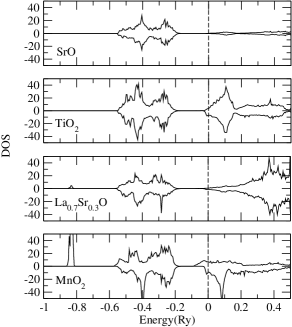
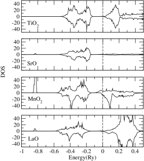
Considering the two situations where ferromagnetism is found to be stable at the interface, we looked at spin polarisation at as well as at the degree of localisation in the two spin channels. The latter is obtained from the shape of the DOS. The DOS are shown in Figs. 2 and 3 for the TiO2 and the SrO + 2LaO interfaces. We find that the polarisation is actually negative (-10%) for the TiO2 interface. However, the electrons in the minority spin channel are much more localised than those in the majority spin channel as can be seen from the DOS of Fig 2. The SrO interface with two LaO layers inserted has a small positive polarisation (4%) but again the minority electrons are more localised than the majority ones (Fig 3). Moderate to high TMR effects were found in LSMO-based junctions. This is a clear indication that when the value of the TMR is not given by the DOS alone but one should take account of the relative degree of delocalisation of the carriers in the two spin channels mazin99 . It is not possible, though, to see the localisation of the carriers, due to disorder, from the DOS. The latter is smooth through any localisation transition. However the minority spin electrons are more likely to be below the mobility edge than the majority electrons. The DOS show that the occupied bandwidth of the minority spin electrons is much reduced compared to that of the majority ones. We, therefore, expect the arguments of Pickett and Singh pickett96 to hold in the current situation. The DOS show averaged properties because of the integration over both parallel and perpendicular momenta. The localisation can be even stronger when considering only which is relevant to tunnelling.
The change in the magnetic coupling at the interface is related to two key ingredients : the doping level and the mobility (kinetic energy) of the electrons. In order to compare the amount of electrons on each MnO2 layer we integrated the layer-projected DOS from the bottom of the conduction band up to bearing in mind that these bands originate from the Mn orbitals with a small hybridisation with O 2p orbitals. These values are given in Table 3 for the four scenarios considered: TiO2 interface, SrO interface and the two cases when one or two La0.7Sr0.3O layers are substituted by LaO at the SrO interface. The calculated charges are also compared with estimates from an ionic picture. The latter are obtained by assuming a contribution of electron from each neighbouring La1-xSrxO layer to a particular MnO2 layer. If we consider the SrO interface for instance then the ionic value is , given that the MnO2 layer is sandwiched between a La0.7Sr0.3O layer which contributes and a SrO layer which contributes 0 electrons. As expected there are deviations from the ionic values because of band formation and hybridisation. The largest of these deviations occurs at the TiO2 interface where we find 0.68 electrons whereas from the ionic picture we have 1.05 electrons. In this case, however, and as can be seen from Fig. 2, there are a few electrons (0.41) in the conduction band of the interface TiO2 layer. The effect of the number of carriers on magnetic coupling is seen when comparing the charge on the interface MnO2 layer between the two types of interfaces. The charge at the SrO interface (0.41) has been reduced below the bulk value (0.67). This difference accounts for the observed AF coupling for the SrO interface whereas the FM solution is stable for the TiO2. All the other layers have roughly the same charge. However, the effect of the number of carriers cannot be separated completely from the effect of their mobility as we will discuss below.
| Interface and doping | Calculated charge | Ionic charge |
|---|---|---|
| TiO2: MnC | 0.64 | 0.70 |
| TiO2: MnI-1 | 0.65 | 0.70 |
| TiO2: MnI | 0.68 | 1.05 |
| SrO: MnC | 0.67 | 0.70 |
| SrO: MnI-1 | 0.62 | 0.70 |
| SrO: MnI | 0.41 | 0.35 |
| SrO +1 LaO: MnC | 0.65 | 0.70 |
| SrO +1 LaO: MnI-1 | 0.71 | 0.85 |
| SrO +1 LaO: MnI | 0.54 | 0.50 |
| SrO +2 LaO: MnC | 0.65 | 0.70 |
| SrO +2 LaO: MnI-1 | 0.75 | 1.00 |
| SrO +2 LaO: MnI | 0.50 | 0.50 |
The effect of the mobility of the electrons can be seen by comparing the number of carriers in bands in the bulk and at the TiO2 interface. Although this value is indeed slightly larger at the interface, we find that ferromagnetic exchange is smaller at the interface as compared to the bulk. This can be attributed to the fact that the carriers at the interface are confined to a 2D motion which, normally, favours antiferromagnetism whereas in the bulk the interlayer hopping mediates a stronger FM coupling. In the case of the SrO interface the charge on the interface MnO2 layer is of 0.41, much smaller than the bulk value of 0.67. This corresponds to a doping in the ionic picture. With this amount of doping, well above 0.5, even the bulk material is in a AF, and possibly charge ordered, state. This high level of doping combined with the confinement of electrons due to the interface leads to a very strong tendency to AF coupling to the bulk as found from our total energy calculation (see Table 2). Upon inserting one LaO layer the charge at the interface MnO2 increases from 0.41 to 0.54, its ionic value being 0.50 in this case. This value is the theoretical ionic limit for the SrO interface. The coupling is still AF though. By introducing a second LaO layer we see indeed that the charge at the interface remains . The excess charge goes to the MnO2 layers adjacent to the interface. On these layers the electrons have more mobility and as a result lead to stronger FM coupling between bulk and interface. We see then that increasing the number of carriers at, but not limited to, the interface MnO2 layer leads to a FM coupling between interface and bulk and also to the preservation of transport half-metalicity. Considering only the case of two layers of LaO inserted at the SrO interface of a STO/La0.6Sr0.4MnO3 junction, an increase of TMR (50% to 170%) was reported yamada04 .
In summary, we have studied the two possible interface terminations of a LSMO/STO/LSMO junction and found that the TiO2 interface preserves the ferromagnetism and the transport half-metallicity, characteristic of bulk LSMO, both of which are very important for a high TMR. For the SrO interface, on the other hand, it is necessary to add carriers to the interface and also to the neighbouring MnO2 layers in order to recover these properties. The number of carriers and their mobility are crucial for enhancing ferromagnetism at the interface. This work has therefore provided a consistent interpretation to two different sets of experimental data on LSMO/STO interfaces. It is hoped that it will serve as a guide to experimentalists in order to improve the efficiency of manganite-based tunnel junctions.
References
- (1) J.-H. Park et al., Nature (London) 392, 794(1998).
- (2) B. Nadgorny et al., Phys. Rev. B 63, 184433(2001).
- (3) I. I. Mazin, Phys. Rev. Lett. 83, 1427(1999).
- (4) Izumi et al., Appl. Phys. Lett. 73, 2497(1998)
- (5) L. Samet et al., Eur. Phys. J. B 34, 179(2003).
- (6) M. Bowen et al., Appl. Phys. Lett. 82, 233(2003).
- (7) M. O. Bowen, PhD thesis, Univesité Parix XI (2003).
- (8) H. Yamada et al., Science 305, 646(2004).
- (9) M. Izumi et al., Phys. Rev. B 64, 064429(2001).
- (10) M. Izumi et al., J. Phys. Soc. Jpn. 71, 2621(2002).
- (11) W. M. Temmerman et al., in Electronic Density Functional Theory: Recent Progress and New Directions, edited by J. F. Dobson, G. Vignale, and M. P. Das, (Plenum, New York) 1998.
- (12) Z. Szotek et al., Phys. Rev. B 47, 4029(1993); A. Svane and O. Gunnarsson, Phys. Rev. Lett. 65, 1148(1990).
- (13) G. Banach and W. M. Temmerman, Phys. Rev. B. 69, 04427(2004).
- (14) E. A. Livesay et al., J. Phys.: Condens. Matter 11, L279(1999).
- (15) W. E. Pickett and D. J. Singh, Phys. Rev. B. 53, 1146(1996); Phys. Rev. B. 55, R8642(1997).
- (16) R. W. Godby et al., Phys. Rev. B 37, 10159(1988).
- (17) H. Zenia et al., Phys. Rev. B 71, 024416(2005).
- (18) V. Garcia et al., Phys. Rev. B 69, 052403(2004).