Vortex creation during magnetic trap manipulations of spinor Bose-Einstein condensates
Abstract
We investigate several mechanisms of vortex creation during splitting of a spinor BEC in a magnetic trap controlled by a pair of current carrying wires and bias magnetic fields. Our study is motivated by a recent MIT experiment on splitting BECs with a similar trap, where unexpected fork-like structure appeared in the interference fringes corresponding to interference of two condensates, one with and the other without a singly quantized vortex. It is well-known that in a spin-1 BEC in a quadrupole trap a doubly quantized vortex is produced topologically by a “slow” reversal of bias magnetic field . We find that in the magnetic trap considered it is also possible to produce a 4- and 1-quantized vortex in a spin-1 BEC. The latter is possible, for example, during the magnetic field switching-off process. We therefore provide a possible explanation for the unexpected interference patterns in the experiment. We also give an example of the creation of singly quantized vortices due to “fast” splitting, which is a possible alternative mechanism of the interference pattern.
pacs:
03.75.Dg, 03.75.Nt, 03.65.VfI Introduction
Coherent manipulation of matter-waves is presently a very important experimental and theoretical field. Coherent splitting of matter waves into spatially separate atomic wave packets with a well-defined relative phase is necessary for atom interferometry and quantum information processing applications. Bose-Einstein condensates (BECs) open new unprecedented perspectives in this direction. Coherent splitting of a BEC was recently realized both in an optical double-well trap Shin2 and in a magnetic chip-based double-well trap Shin . In the latter experiment, the magnetic trap was produced by a pair of current carrying wires and a bias field used to control the distance between the wells Hinds . An intriguing feature of this experiment was appearence of a fork-like structure in the absorption image of interference fringes designating creation of a singly quantized vortex in one of the wells. Thus perturbations during condensate manipulations were violent enough to generate vortices. To identify possible mechanisms of vortex creation is an inevitable challenge for future pursuit of BEC interferometry with such kind of an experimental configuration.
Here we study two independent scenarios that could lead to vortex creation. One of them is the phase imprinting during the switching-off process (due to different decay times of the bias fields and the fields of the two wires), while the other is dynamical vortex creation during fast splitting. Although the switching-off time in the particular experiment Shin was only about 20 s (a duration much shorter than the inverse of any trap frequency), it is slow as compared to the Larmor frequency in the magnetic field of order of 1G. Therefore, adiabatic imprinting might take place. On the other hand, the authors of Ref. Shin think the phase imprinting mechanism is an unlikely explanation for the vortex creation since they have never observed interference pattern of a doubly quantized vortex (which is created topologically in spin-1 condensates when zero point of the magnetic field crosses through condensates). We find realistic scenarios for a singly quantized vortex interference pattern to appear as a result of topological phase imprinting during the switching-off process. Indeed as we assume exponential decay of magnetic fields produced by the two wires and the bias field with different decay constants, with parameters close to the experiment we obtain numerically that a large part of the atoms (about half of the condensate) can be transferred to the component (i.e., with in -quantized basis, see Eqs. (1) and (2) for notation) which has singly quantized vortices around each of the two minima of the magnetic field. In contrast, when we try to obtain doubly quantized vortices using bias field reversal, it turns out to be more difficult. At such short timescales, only a small part of the population is transferred to the component with doubly quantized vortices, while the rest of the population is redistributed among other components. Creation of doubly quantized vortices in such a configuration requires times of the order of hundreds of s. We also present an example of dynamical vortex creation during fast splitting. In this case, the condensate (including the component) acquires winding phase during the splitting process. This leads to clear fork-like structures in all components and thus the total density upon expansion. Although in our calculations this requires a sufficiently shorter time of splitting than that which was actually effected in the real experiment Shin , it might be caused by the oversimplified model (without jitter or fluctuations of the magnetic field, etc).
The rest of the paper is organized as follows. In Sec. II we introduce the model (spinor BEC described by 2D GP equation with spin degrees of freedom), describe the configuration of the magnetic field given by the two-wires setup, and its weak- and strong-field seeking states. In Sec. III, we present numerical results on vortex creation in the system. In Sec. IIIA we study several examples of how an unexpected topological phase imprinting could have taken place in the MIT experiment. There we take into account gravity and use realistic parameters relevant to the experiment. We assume that after switching off the magnetic field the field decays faster than transversal magnetic field , which can lead to the phase imprinting. In Sec. IIIB we present examples of dynamical vortex creation during splitting process. When split slowly in 30 ms, the condensate develops no vortex. However, reduction of the splitting duration to about 5 ms, vortices are created. Then, even in the case where the switching-off process leaves all population in the initial component, expansion of condensates produces very clear forks in the interference pattern.
II The model
II.1 Spinor Bose condensate
We consider a BEC of alkali atoms with hyperfine spin using the -quantized basis Machida . The order parameter is expanded as
| (1) |
where are eigenvectors of :
| (2) |
We use the time-dependent form of the GP equation with spin degrees of freedom developed in Machida :
| (6) |
where are the angular momentum operators in the basis of the eigenvectors of :
| (16) |
and is the spin-independent and is the spin-dependent interaction coefficients. Here the scattering lengths and characterize collisions between atoms with total spin 0 and 2, is the atomic mass.
We consider a condensate of 23Na, which was used in the experiment of Shin . Parameters of Na are kg, nm, nm Ketterle . Spin-independent potential is provided either by gravity as in the MIT experiment (, we consider this case in Section 3), or, in principle, “optical plug” can be used. We assume the wavefunction of either component does not depend on the coordinate, i.e. the condensate is quasi-2D. We therefore use two-dimensional nonlinearity parameters and which are related as . Configuration of the magnetic field is described in the next subsection.
II.2 The magnetic trap
We use a two-wires setup suggested in Ref. Hinds . It was used in a recent experiment of Y. Shin et al. Shin , where several important elements were added making the system essentially three-dimensional. We consider a two-dimensional trap here to simplify numerical calculations. Magnetic field produced by two parallel current-carrying wires is given by
| (17) |
where is the distance between the wires.
Additional magnetic field is added along direction, and bias field is added in direction: . For weak-field-seeking atoms, amplitude of magnetic field plays the role of trapping potential (while the potential for strong field-seeking atoms is ). At certain critical the trap potential has a single minimum located on distance away from the surface, at the middle of the two wires. At greater or smaller than the potential has two wells: when , the two wells are separated in the direction, while for they are separated in the direction and has equal -coordinates of their centers. Addition of bias magnetic field along the -axis rotates these two wells in the plane. It is important that the critical single well potential is harmonic (corresponding to hexapole configuration of magnetic field), while either of the separated double wells is quadrupole. We assume uniform is applied to the system. In numerical calculations, we used the parameters close to the experiment of Ref. Shin : m (this corresponds to the distance between the wires of 300m), G, G.
II.3 Strong- and weak-field seeking states in two-wires trap
The important feature of static magnetic traps is that it confine the weak-field seeking state(s) (WFSS) which has a higher energy than the strong-field seeking state(s) (SFSS). Therefore, there is some difficulty in numerical preparation of initial states, since straightforward imaginary time propagation would lead to SFSS. One need to search for a solution using a WFSS ansatz which is derived from the eigenvector of the matrix. The eigenvalues of are ( where ) and 0 (the latter corresponding to the neutral field-seeking state, NFSS), and the eigenvector corresponding to WFSS is
| (18) |
Suppose we have configuration with (so the wells are coalesced in a single harmonic well). When in the vicinity of the minimum of the well, where is the polar angle around the point of the minimum. The weak-field-seeking state order parameter has the form
| (19) |
where is the amplitude (common for all three components). At large , almost all population is in component. In order to avoid vorticity in this component, we should choose . Substituting ansatz (19) into GP equation, one obtains the one-component equation for the amplitude which can be solved using imaginary time propagation to find a ground state. However, it is also possible to propagate the original three-component GP equation in the imaginary time, restricting the solution to the anzatz (19). We used both algorithms in our calculations.
One can see that one obtains a vortex with vorticity 4 from the initial non-vortex state in the critical hexapole trap by reversal of . When , we have two quadrupole traps. In that case reversal of leads to doubly quantized vortices in either trap, as was studied in several works recently (for example, Ref. Machida ). It is important that the component in that case contains singly quantized vortices.
III Vortex creation during realistic magnetic trap manipulations
III.1 Phase imprinting
Bias fields and and the two-wires magnetic field are created by different sources. During a switching-off process, they can behave differently. Examples of nontrivial consequences of nonsynchronous decreasing processes of magnetic fields in other situations were considered in Refs. Zhou ; Zhang . In order to achieve topological imprinting, we consider here the switching-off process with decaying faster than (in our model calculations, we assume the fields and decay synchronously, while the field decays faster). We found a time of the order of tens of s is enough to transfer a large part of the atoms to component with singly quantized vortices in each well.
In contrast, we found that in order for reversal to produce considerable population of component with doubly quantized vortices, much longer times are required, i.e. hundreds of s. In the experiment of Ref. Shin switching-off time was s. Larmor frequency at is kHz corresponding to s. Therefore, despite very short switching-off time, ”adiabatic” phase imprinting still might take place. We checked this guess numerically.
Four stages of the process were carefully examined: preparation of initial state, splitting, switching-off process, and the free expansion. Firstly, we prepare the initial state in the single (critical) harmonic well using imaginary time propagation, as described in the previous Section. (In the real experiment, the condensate was prepared initially at mG in the bottom well of the double-well potential, but it is not important for our present purpose). When, the condensate was split by ramping from 0 to mG in real time. During this stage, almost all the population is in component, because the field of 1G is large as compared with magnetic field in the vicinity of the minima of magnetic field, where the condensate resides. Provided the splitting is slow, component remains without vortices (however, at fast splitting it acquires phase winding, this case is considered in the next subsection). During the third stage, the magnetic field was turned off. Faster decay of may lead to creation of two singly quantized vortices in component in either of the two wells. This would result in two fork-like structures in the interference pattern of this component (only one of the forks points up, because charges of the topological vortices in either well are the same (positive)). The interference fringes were formed during the forth stage of numerical calculations: expansion of the two condensates without magnetic field. For numerical purposes, we also turned off the gravity field in the forth stage, but we suppose this does not influence results significantly. In the real experiment, typical time of expansion was about 22 ms. In our calculations, we typically calculate up to 4 ms only.
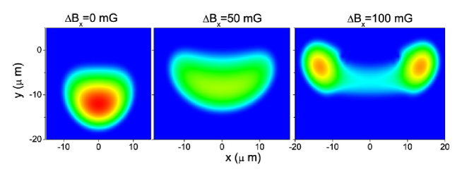
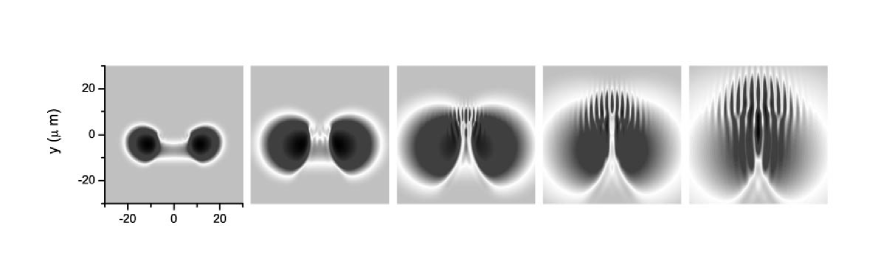
In Fig.1, fast splitting of the condensate is shown. The condensate was prepared in the merged well (at ). Splitting was done approximately in 5 ms, much faster than in the experiment. In Fig.2, slow splitting of the condensate is monitored (time of splitting about 30 ms). The final state is slightly different about 2 % of the initial population was lost because during very slow splitting. The atoms that make transitions from WFSS to SFSS fly away (they fly up towards the wires and are removed by absorbing potential on the boundaries of the mesh). The atoms that make transitions to NFSS, fly down because of the gravity (and are also removed).
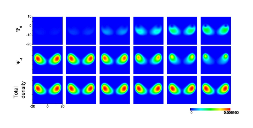
Densities and phases of the components of the split condensate are presented. Component has no vorticity, while has singly quantized vortices in both wells and has doubly quantized vortices. Since , almost all population is in component without vorticity.
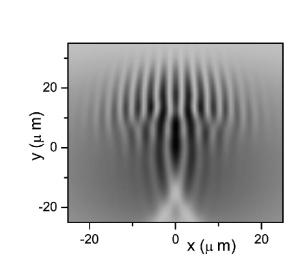
In Fig. 3, interference fringes formed during expansion of the condensates are shown. Magnetic fields were switched off in approximately s in such a way that no transition from component occured ( was decreased more slowly than ).
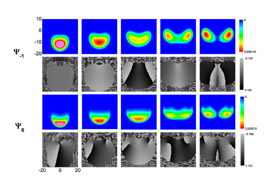
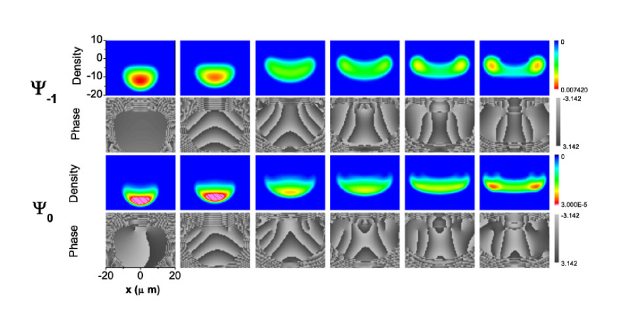
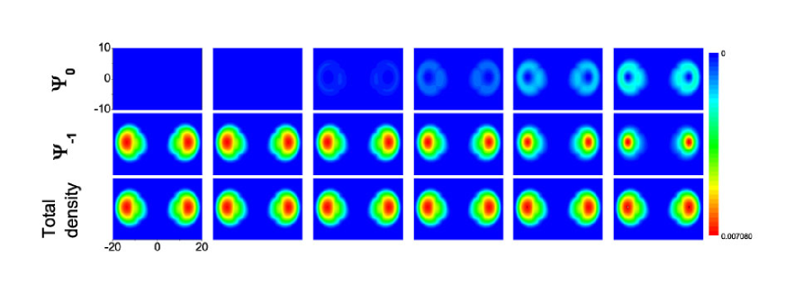
Then, we consider a case where is decreasing faster than . In Fig.4, the process of topological vortex formation is shown during switching-off process. Magnetic fields were decreasing exponentially, with decaying faster, and were turned off completely at (s is the characteristic time period used in the program). About half of the total population were transferred to the component . An important feature of nonadiabatic transitions during process of switching-off can be noticed. The part of condensate in component residing far from the minima of the magnetic field is more easily converted to other components than the part near the minima. As a result, decreasing slices out a part of the condensate around the minima of the magnetic field and leaves it in the initial component. This is due to the fact that in the region where is not zero, a nonvanishing gap between WFSS and NFSS remains; besides, the stronger the field is, the more slowly the total magnetic field rotates, making it easier for the spin of an atom to follow it. Quantitatively, nonadiabatic transitions due to nonsynchronously decreasing trapping magnetic fields (in other configurations) were considered recently in Ref. Zhang by generalizing the Landau-Zener formula for the multilevel case. It can be seen also that during fast switching-off process, the total density is almost unaffected, therefore the nonlinear interaction coefficient plays no role in the process.
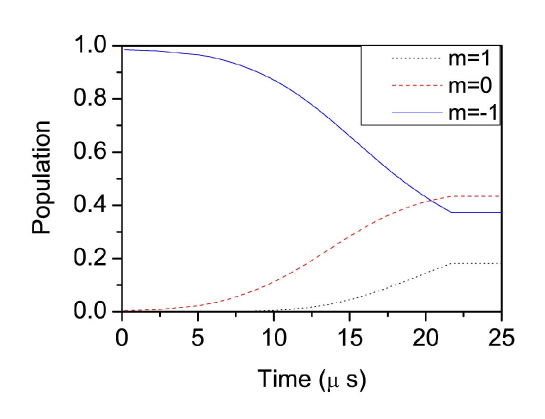
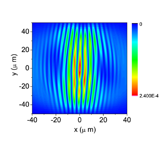
Time evolution of populations of the components is shown in Fig. 5. In Fig. 6, interference fringes formed during expansion of the condensates are shown. Fork-like structure is seen in the component .
(a)
 (b)
(b)
Topological vortices in component in both wells has equal charges. Therefore, only one fork points up (Ref. Ketterle3 ). The component rotates clockwise during expansion due to equal charge of the vortices, and the fork is moving up. Because of this, although during our calculations it has not appeared in total density profile, we believe that after a longer time it will show up (note that almost half of the total population is in the component). The absence of the fork in the total density profile on early stages of expansion is related to the above-mentioned behavior of the switching-off process that leaves component residing near the minima of magnetic field almost unaffected. After the switching-off this component therefore is concentrated at the same places where the phase singularities of component are located.
For clarity, we give also an example of vortex formation without gravity (Fig.9). Here, the both forks are clearly seen.
III.2 Dynamical vortex creation
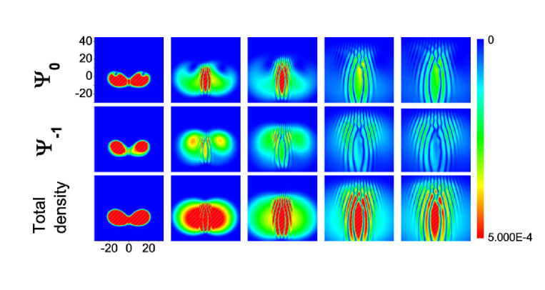
In Fig.7, fast splitting of the condensate is monitored. Dynamically created vortices appear in all the components (in component dynamical and topological vortices coexist). Centers of dynamically created vortices (the phase singularities) lie outside the condensate, but branch cuts go through the condensate causing phase winding across it. So this situation is different from the so-called ghost vortices appearing in studies of stirring condensates (Ref. Ueda ). Although vortices are almost not visible in the density profile of the condensate, its expansion leads to characteristic fork-like structures in the interference fringes due to the phase winding.
(a)
 (b)
(b)
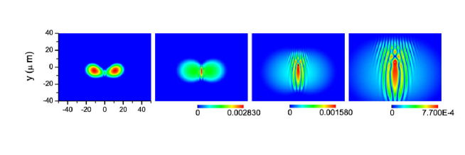
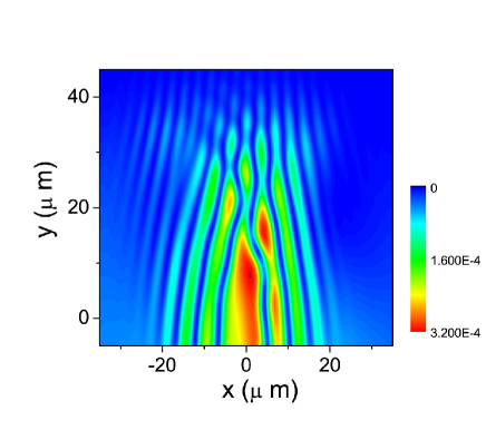
Magnetic field was switched off in such a way that almost no transfer to occur. So, component does not influence the dynamics. In Fig. 8, interference fringes resulted from the subsequent expansion are shown. Two fork-like structures (which appear in all components) are clearly seen. Vortices in the two condensates have opposite charges, therefore the forks point up (splitting of the condensate on two parts in the presence of gravity effectively causes rotation of each part in opposite directions).
(a)
 (b)
(b)
To finish off, let us notice that the calculations reported were done using the sin-DVR method (with a spatial mesh of grid points), and time propagation using the Runge-Kutta method (the method is the generalization of the one used in Ref. hyro to the case of spinor condensates). We try to model the system as close to the experimental one as possible. However, we found that, for example, factor does not affect the results, i.e., the results are qualitatively the same with . The most important deviation of the model from the experimental system is its reduced dimensionality. The real system is three-dimensional, with nonuniform magnetic fields, with an additional two pairs of wires creating magnetic fields to compensate partly for nonuniformity of the base magnetic fields and asymmetry, etc. Such complication is presently beyond our available resources. However, we believe the study of the idealized model do allow to discuss different mechanisms of vortex creation in the experiment.
IV Conclusion
The authors of the experimental work Shin supposed the phase imprinting mechanism to be unlikely for explaining the appearance of the fork-like structure and that “the observed phase singularity definitely shows the breakdown of adiabaticity”. To the contrary, we found a realistic scenario based on nonsynchronous decreasing processes of the magnetic fields can explain the phase singularity even within the assumption of adiabatic evolution.
However, we found that fast splitting can also lead to dynamical vortex creation, and that the dynamically created vortices produce interference patterns with the forks of better contrast. Detailed study of these processes is left for future research. In any event, the splitting of a spinor BEC is a rather violent process so that further consideration of atom interferometry with spinor BEC is necessary.
V Acknowledgements
A.P. Itin is supported by JSPS. This work was also supported in part by Grants-in-Aid for Scientific Research No. 15540381 and 16-04315 from the Ministry of Education, Culture, Sports, Science and Technology, Japan, and also in part by the 21st Century COE program on “Coherent Optical Science”. TM was also supported in part by a financial aid from the Matsuo Foundation. We would like to acknowledge useful discussions with Prof. Y.S. Kivshar and Prof. Nakagawa.
References
- (1) Y. Shin et. al, Phys. Rev. Lett. 92, 050405 (2004).
- (2) Y. Shin et. al, Phys. Rev. A 72, 021604 (2005).
- (3) E. A. Hinds, C. J. Vale, and M. G. Boshier, Phys. Rev. Lett. 86 , 1462 (2001).
- (4) T. Isoshima et al., Phys. Rev. A 61, 063610 (2000).
- (5) Y. Kawaguchi, M. Nakahara, and T. Ohmi, Phys. Rev. A 70, 043605 (2004).
- (6) D. M. Stamper-Kurn and W. Ketterle, in Coherent Atomic Matter Waves, edited by R. Kaiser, C. Westbrook, and F. David (Springer, Heidelberg, 2001).
- (7) P. Zhang et al., Phys. Rev. A 73, 013623 (2006).
- (8) X.Q. Ma et. al, cond-mat/0509776 (2005).
- (9) M. Tsubota, K. Kasamatsu, and M. Ueda, Phys. Rev. A 65, 023603 (2002).
- (10) O.I. Tolstikhin, T. Morishita, and S. Watanabe, Phys. Rev.A 72, 051603(R) (2005).
- (11) S. Inouye et. al, Phys. Rev. Lett.87, 080402 (2001).