Asymmetric Reversal in Inhomogeneous Magnetic Heterostructures
Abstract
Asymmetric magnetization reversal is an unusual phenomenon in antiferromagnet / ferromagnet (AF/FM) exchange biased bilayers. We investigated this phenomenon in a simple model system experimentally and by simulation assuming inhomogeneously distributed interfacial AF moments. The results suggest that the observed asymmetry originates from the intrinsic broken symmetry of the system, which results in local incomplete domain walls parallel to the interface in reversal to negative saturation of the FM. Magneto-optic Kerr effect unambiguously confirms such an asymmetric reversal and a depth-dependent FM domain wall in accord with the magnetometry and simulations.
pacs:
75.25.+z, 75.60.-d, 75.70.-iExchange coupling between a ferromagnet (FM) and an antiferromagnet (AF) has been intensely studied due to the fundamental interest in inhomogeneous magnetic systems and its central role as a magnetic reference in various devices. In most magnetic systems, time reversal symmetry is present and manifested by a symmetric magnetization curve relative to the origin. This symmetry also requires that the magnetization reversal from positive to negative saturation be identical to the reverse process. However, in a FM/AF system, exchange bias (EB) develops below the AF Néel temperature producing a shift () of the hysteresis loop along the magnetic field axis Meiklejohn and Bean (1956). Therefore, with the shift breaking the time reversal symmetry, magnetization reversal symmetry is no longer required. In fact, asymmetric reversal was observed by polarized neutron reflectometry Fitzsimmons et al. (2000), photoemission electron microscopy Blomqvist et al. (2005), magnetotransport Liu et al. (2001), magneto-optical indicator film Nikitenko et al. (2000), and magneto-optical Kerr effect Eisenmenger et al. (2005). In some systems the reversal along the decreasing branch is dominated by transverse magnetic moments which was interpreted as due to coherent magnetic rotation. The absence of transverse moments in the increasing branch reversal was interpreted as domain wall propagation Fitzsimmons et al. (2000); Blomqvist et al. (2005). Different, even opposite scenarios were also found Eisenmenger et al. (2005); Gierlings et al. (2002); Leighton et al. (2001). Despite the well established experimental evidence and proposed theoretical models Li and Zhang (2000); Beckmann et al. (2003); Camarero et al. (2005), the origin of this asymmetry remains a controversial and highly debated issue 34T . This situation is further complicated by the lack of knowledge of the interface, crystal imperfections, complex FM and AF anisotropy energies, and training effect. While these factors are important for each individual system, the fundamental connection of the reversal asymmetry to the broken symmetry intrinsic in the inhomogeneous system is overlooked.
In this Letter, we have investigated a simple model system using a variety of experimental techniques combined with numerical simulations. We establish a critical link between this unusual reversal asymmetry with the time reversal asymmetry in these systems. Namely, in reversal toward the two FM saturated states, the intrinsic asymmetry gives rise to different competing mechanisms, thus different reversal processes.
FeF2/(Ni, Py) bilayers were prepared for this study. FeF2 is an AF with a Néel temperature = 78 K, and a large uniaxial anisotropy kJ/m3 along [001] direction, hence can be considered as a model Ising system Hutchings et al. (1970); Strempfer et al. (2003), with the AF spins frozen along [001] at low temperatures 30s . The Ni or Py (Ni81Fe19) is polycrystalline with a negligibly small crystalline anisotropy, except for a small growth-induced uniaxial anisotropy along FeF2 [001] Petracic et al. (2005). This system is thus in close approximation with simple theoretical assumptions.
The bilayer was grown by e-beam evaporation on a single crystal MgF2(110) substrate, where FeF2 (110) grows epitaxially untwinned Shi et al. (2004); Petracic et al. (2005). Vector vibrating sample magnetometry (VSM) of FeF2 (50 nm) / Ni (21 nm) / Al (7.6 nm) gives simultaneously the in-plane longitudinal (parallel to the magnetic field) and transverse (perpendicular to the magnetic field) magnetic moments Olamit et al. (2005); Daboo et al. (1995). The magnetic field is applied along the FeF2 easy axis [001] with a small misalignment that defines the sign of the transverse component during reversal Olamit et al. (2005); 34T . Square hysteresis loops are found above along [001] Petracic et al. (2005). Cooling the sample in a field = 0.2 T from T = 150 K to 15 K yields an EB field = -0.1 T (Fig. 1a) and virtually no coercivity. Both longitudinal and transverse hysteresis loops exhibit a clear asymmetry. Starting from positive saturation, the reversal occurs with a sharp corner in the longitudinal component and an abrupt increase in transverse component to over 75% of the saturation magnetization. Then the FM gradually approaches negative saturation, evidenced by the long tail in both components. A significant non-zero transverse component is found even at = -0.5 T. In the increasing field sweep, Ni is saturated almost immediately after the reversal. The asymmetry of the two FM orientations, especially the long tail around negative saturation, is key to understanding the asymmetric reversal.
We modeled the asymmetric reversal process with micromagnetic simulations 35o using a 20 nm thick Ni layer with lateral size 500500 nm2, discretized into 552 nm3 cells. The Hamiltonian of the system is given by,
where the three summed terms include FM exchange energy, FM anisotropy and Zeeman energy, and FM/AF interfacial interaction, respectively. The AF is assumed to be frozen during the hysteresis cycle, thus its energy contribution remains constant and is not considered in the Hamiltonian above. is the magnetic field applied along the axis with misalignment similar to the experiment. and are the magnetic moment and volume of each cell, respectively. The reduced moment is defined by . We used the nearest-neighbor exchange constant pJ/m and the saturation magnetization kA/m for Ni Skomski (2003). The small growth-induced anisotropy of the Ni layer is taken into account by a uniaxial anisotropy along the axis with kJ/m3 obtained from measurements along the hard axis above . The dipolar interaction is approximated by a shape anisotropy along the axis (out-of-plane) with kJ/m3, which keeps the moments in the sample plane and avoids boundary effects.
The AF is modeled by a monolayer of spatially inhomogeneous frozen moments, , exchange coupled to the bottom layer of the FM with an adjustable interfacial coupling from meV up to Hutchings et al. (1970). We introduced AF grains of average size 2525 nm2 to simulate the inhomogeneous interfacial couplingShi et al. (2004). with , consists of two random quntities: denoting the intergrain variation, and the intragrain variation. varies as 10.35 between grains, while varies as (72)% between cells. This 7% assumption is based on recent experiments which found net frozen AF interfacial moments with about 4% Ohldag et al. (2003) or 7% Kappenberger et al. (2003) coverage that contribute to EB. Crucial parameters for the simulation include the product of the uncompensated moment coverage and interfacial coupling, and intergrain fluctuation. The former defines the effective coupling strength. The latter describes the interfacial inhomogeneity modulated over a length scale of the grain size (25 nm), comparable with the FM domain wall width 82 nm. This spatial modulation of leads to an inhomogeneous pinning on the FM, and is essential to explain reversal process revealed in the experiment. However, the intensity of the modulation is not essential: 20% to 50% standard deviation in gives similar results. The resultant spatial variation of is shown in the inset of Figure 1.
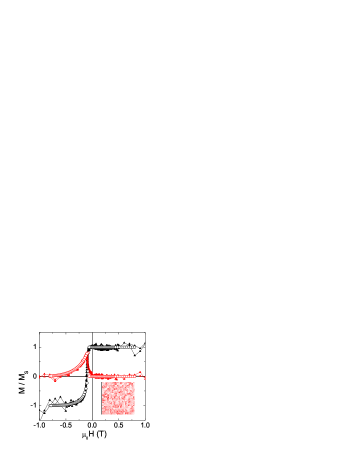
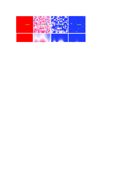
The simulation (Fig. 1) matches well both the longitudinal and transverse hysteresis loops exhibiting the same asymmetry as the experiment 37c . The bottom and side view of the FM spin configuration during the hysteresis (Figure 2) shows domains evolving both laterally and in the depth. In positive saturation, the FM is uniformly magnetized throughout the thickness because both the applied magnetic field and interfacial coupling favor this orientation. As the magnetic field decreases, the reversal is initiated from the top of the FM far away from the interface while the bottom pinned by the AF remains in the positive direction. An incomplete (non-) FM domain wall (IDW) is thus formed parallel to the interface. As the field decreases further, these FM IDWs slowly shrink laterally and squeeze close to the interface. Even at = -0.8 T, the FM is not saturated at some interface regions. This lateral domain formation is the result of the spatially varying . The regions in the FM most resistant to reversal are where the strongest local interfacial pinning is found. As the field increases, these regions become nucleation sites for the development of local IDWs both laterally and in the depth. Therefore, these local IDWs result from the competition between inhomogeneously distributed interfacial pinning and the magnetic field. Due to the unidirectional nature of the AF pinning field, it only competes with the Zeeman energy in approaching negative saturation, while they both stabilize the FM when positively saturated. This simulation demonstrates that the local development of IDWs constitutes the dominant asymmetric reversal mode. Although similar exchange spring is claimed in hard/soft magnetic structures Kneller and Hawig (1991); Fullerton et al. (1998), it does not lead to asymmetric reversal Davies et al. (2005). In addition, this incomplete domain wall is unusual in EB because the interfacial coupling energy is much weaker than that in a conventional exchange spring, thus it was never convincingly observed and was overlooked in most EB studies.
When a finite anisotropy of pinned AF moments is included in the simulation, the IDW is pushed into the AF forming a hybrid domain wall across the interface, but the main features of the reversal process remain unchanged. Since the anisotropy of the FM is usually much smaller than that of the AF, the FM-side of domain wall dominates the reversal.
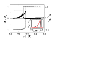
The result implies several important features of the local IDW reversal process. First, the FM domain wall depth-dependence is crucial for the asymmetric reversal process. An important signature of this behavior is the asymmetric development of transverse magnetic moments. This behavior tends to be smeared out by AF twinning or polycrystallinity, and/or more complicated FM or AF anisotropy energy terms. It is worth noting that this asymmetry of approaching two saturated states may seem different from the asymmetry of two field sweep branches observed before in other systems, where a sharp corner is found in the decreasing branch and a rounded one for the increasing one Liu et al. (2001); Eisenmenger et al. (2005). However, they are essentially the same except for the small FM uniaxial anisotropy, thus negligible coercivity in our system. If the FM uniaxial anisotropy is increased to = 50 kJ/m3 and a fanning of the AF pinning moment in the sample plane is included, the simulated hysteresis loop displays the same asymmetry as observed before together with an irreversible transverse loop (Fig. 3) Liu et al. (2001); Eisenmenger et al. (2005). Second, the local nature of the IDW due to the interfacial inhomogeneity is crucial in the model. It leads to asymmetric lateral domains due to unsynchronized winding of DW in the depth, and may clarify the present confusion and debate based on lateral multi-domain observations. It also explains the long tail of the hysteresis loops, which would otherwise disappear if is not included as in Kiwi’s model (Fig. 3 inset) Kiwi et al. (1999). Since a square hysteresis loop is observed above , this low temperature behavior must arise from the interfacial inhomogeneity.
So far we demonstrated that the local IDWs nucleated in approaching the negative saturation cause the asymmetric reversal. This result is unambiguously confirmed by MOKE experiments probing the FM-air and FM-AF interfaces independently. In this experiment, a sample with MgF2 (110) / FeF2 (50 nm) / Py (70 nm) / Al (4 nm) is cooled below in = 0.02 T, and MOKE is performed on both the top and bottom surfaces of the sample with HeNe laser ( = 632.8 nm) at 45 degree incidence (Fig. 4 inset (c)). Probing the depth dependence of the FM domain structure is possible because the 28 nm penetration depth of the light CRC (2004) is less than half of the Py thickness, and both MgF2 and FeF2 are transparent. A clear difference is seen between the two MOKE measurements (Fig. 4). Probing the FM-AF interface shows a much more rounded and longer tail compared with the one from FM-air interface, confirming the existence of domain structures in the depth. The sample was also measured using SQUID magnetometry to which the entire sample contributes equally. The resultant hysteresis loop lies between the two MOKE loops.

We also performed micromagnetic simulations under identical assumptions using the same parameters as above to generate the random frozen AF moments 40P . The exponential decay of MOKE in the FM is simulated by giving each FM discretization layer in the depth an appropriate weight according to the Py 28 nm penetration depth. A very good agreement is obtained for all three hysteresis loops simultaneously with a slight adjustment of the interfacial coupling 38c . At = -0.06 T, a large difference between the two MOKE measurements is observed. The simulated spin configuration at this field shows that the FM close to the FM-AF interface is only partially reversed forming lateral domain patterns, while at the FM-air interface the FM is fully reversed (inset (a) and (b) of Figure 4). This confirms that the local IDW model leads to asymmetrically rounded hysteresis loops.
In summary, we found strongly asymmetric hysteresis loops in a simple model exchange bias system FeF2/(Ni, Py). By combining vector magnetometry, MOKE with micromagnetic simulation, we clearly showed that the asymmetric reversal directly results from the FM domain structure in the depth due to the broken symmetry at the interface. The hotly debated issue over the asymmetric reversal process over the past 5 years solely focused on lateral FM domains, and its origin was controversial until now. FM parallel domains were predicted Kiwi et al. (1999); Stiles and McMichael (1999). However, they were not confirmed experimentally. They were mostly ignored in microscopy studies Blomqvist et al. (2005) and simulations generally assuming the FM to be a single moment Camarero et al. (2005) or one monolayer Beckmann et al. (2003). This situation was mostly due to the weak coupling at the FM/AF interface, and limitations of different experimental and modeling techniques. Dispersions in AF crystallinity and anisotropy also smear out manifestations of parallel domain walls. Our study of a simple EB model system, combining different experimental and simulation techniques, unambiguously demonstrates the presence of such domains and their dominant role on the asymmetric reversal.
Acknowledgements.
We thank M. Kiwi, H. Suhl and C. Miller for illuminating discussions. Work supported at UCSD by US-DOE, at UCD by UC CLE, Cal(IT)2 (Z.-P. L.), Alexander-von-Humboldt Foundation (O. P.), Spanish MECD (R. M., X. B.), Fulbright Commission (R. M.), NEAT-IGERT (J.O.), Catalan DURSI (X. B.) and Alfred P. Sloan Foundation (K. L.).References
- Meiklejohn and Bean (1956) W. H. Meiklejohn and C. P. Bean, Phys. Rev. 102, 1413 (1956).
- Fitzsimmons et al. (2000) M. R. Fitzsimmons et al., Phys. Rev. Lett. 84, 3986 (2000).
- Blomqvist et al. (2005) P. Blomqvist, K. M. Krishnan, and H. Ohldag, Phys. Rev. Lett. 94, 107203 (2005).
- Liu et al. (2001) K. Liu et al., Phys. Rev. B 63, 060403 (2001).
- Nikitenko et al. (2000) V. I. Nikitenko et al., Phys. Rev. Lett. 84, 765 (2000).
- Eisenmenger et al. (2005) J. Eisenmenger et al., Phys. Rev. Lett. 94, 057203 (2005).
- Gierlings et al. (2002) M. Gierlings et al., Phys. Rev. B 65, 092407 (2002).
- Leighton et al. (2001) C. Leighton et al., Phys. Rev. B 86, 4394 (2001).
- Li and Zhang (2000) Z. Li and S. Zhang, Appl. Phys. Lett. 77, 423 (2000).
- Beckmann et al. (2003) B. Beckmann, U. Nowak, and K. D. Usadel, Phys. Rev. Lett. 91, 187201 (2003).
- Camarero et al. (2005) J. Camarero et al., Phys. Rev. Lett. 95, 57204 (2005).
- (12) A. Tillmanns, et al., cond-mat/0509419.
- Hutchings et al. (1970) M. T. Hutchings, B. D. Rainford, and H. J. Guggenheim, J. Phys. C 3, 307 (1970).
- Strempfer et al. (2003) J. Strempfer, U. Rütt, and W. Jauch, Phys. Rev. Lett. 86, 3152 (2003).
- (15) Spin-flop is not observed in the samples discussed here.
- Petracic et al. (2005) O. Petracic et al., Appl. Phys. Lett. 87, 222509 (2005).
- Shi et al. (2004) H. Shi et al., Phys. Rev. B 69, 214416 (2004).
- Olamit et al. (2005) J. Olamit et al., Phys. Rev. B 72, 012408 (2005).
- Daboo et al. (1995) C. Daboo et al., Phys. Rev. B 51, 15964 (1995).
- (20) OOMMF code. http://math.nist.gov/oommf.
- Skomski (2003) R. Skomski, J. Phys. Cond. Mat. 15, R841 (2003).
- Ohldag et al. (2003) H. Ohldag et al., Phys. Rev. Lett. 91, 017203 (2003).
- Kappenberger et al. (2003) P. Kappenberger et al., Phys. Rev. Lett 91, 267202 (2003).
- (24) The interfacial coupling that fits best to the experiment is = -0.88 eV, comparable with the exchange coupling in FeF2 -0.45 eV from Ref. 13. This number is not meaningful in its absolute value because it depends on the assumed 7% frozen AF uncompensated moments.
- Kneller and Hawig (1991) E. F. Kneller and R. Hawig, IEEE Trans. Magn. 27, 3588 (1991).
- Fullerton et al. (1998) E. E. Fullerton et al., Phys. Rev. B 58, 12193 (1998).
- Davies et al. (2005) J. E. Davies et al., Appl. Phys. Lett. 86, 262503 (2005).
- Kiwi et al. (1999) M. Kiwi et al., Appl. Phys. Lett. 75, 3995 (1999).
- CRC (2004) CRC Handbook of Chemistry and Physics (CRC Press, Boca Raton, 2004), pp. 12–133 to 12–156, 85th ed.
- (30) Micromagnetic parameters kA/m and pJ/m of Py used are from Ref. 20.
- (31) The interfacial coupling is found to be -0.75 eV.
- Stiles and McMichael (1999) M. D. Stiles and R. D. McMichael, Phys. Rev. B 59, 3722 (1999).