State tomography of capacitively shunted phase qubits with high fidelity
Abstract
We introduce a new design concept for superconducting quantum bits (qubits) in which we explicitly separate the capacitive element from the Josephson tunnel junction for improved qubit performance. The number of two-level systems (TLS) that couple to the qubit is thereby reduced by an order of magnitude and the measurement fidelity improves to . This improved design enables the first demonstration of quantum state tomography with superconducting qubits using single shot measurements.
year number number identifier
Superconducting circuits containing Josephson junctions provide a promising approach towards the construction of a scalable solid-state quantum computer Nakamura03_cnot ; Vion02 ; Collin04 ; Chiorescu03 ; Bertet05 ; Schoelkopf05 . The phase qubit Martinis02 has significant potential because coupled qubits have been measured simultaneously McDermott05 and the coherence times are reasonably long Martinis05 . The conventional design of phase qubits relies on the Josephson inductance and the self-capacitance of the Josephson tunnel junction to form a non-linear microwave resonator Martinis02 . Losses and noise in either component compromise qubit performance, however, generally the inductive element has been suspected as the root source of decoherence Vanharlingen04 ; Wellstood04 ; Mueck05 . It therefore came as a surprise when the capacitive element was clearly identified as a main source of decoherence Martinis05 . Because of the large intrinsic loss of the junction capacitor, we believe it is not possible to fabricate high fidelity phase qubits using a standard design and amorphous aluminum oxide (AlOx) tunnel barriers.
Can we redesign phase qubits to circumvent or minimize capacitive losses without adversely affecting other desirable qubit properties? Understanding this question has profound implications for other designs of superconducting qubits, and may shed light on methods for reducing noise from two-levels systems (TLS).
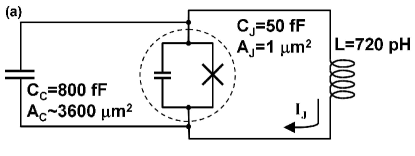
Here, we introduce a new design concept for superconducting phase qubits with which further progress can be achieved in a straightforward manner. The central idea is to explicitly separate out the capacitive from the inductive element of the Josephson junction, allowing their properties to be separately optimized. This idea can be realized by shunting a tunnel junction, which has little self-capacitance but the same Josephson inductance as the conventional design, with a capacitor which has a lower intrinsic loss tangent than the original junction capacitor, as sketched in Fig. 1(a-c). We have fabricated an improved generation of phase qubits whose measurement fidelity is significantly improved. This success enables the first demonstration of quantum state tomography using a superconducting qubit with single shot measurements.
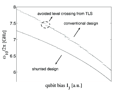
Progress using phase qubits has thus far been hindered by a large density of TLS defects that couple to the qubitMartinis05 . Individual TLS manifest themselves as avoided level crossings (splittings) in the qubit spectroscopy, as shown in Fig. 2. The defects are located in the insulating barrier of the tunnel junction, and have a significant density because of the relatively large intrinsic loss tangent of AlOx. Our model predicts that high fidelity phase qubits are not possible using a standard design and amorphous AlOx tunnel barriers.
However, the number of TLS defects may be dramatically reduced with redesign. Loss of coherence from TLS depends both on the density and size of the splittings, and for low density scales as the square of the tunnel-junction area divided by the total capacitancetlsnote ; Martinis05 . A dramatic improvement in fidelity can thus be achieved by reducing the area of the tunnel junction from to while holding its critical-current constant, and keeping the total capacitance constant by adding an external low-loss capacitor. With a decrease in the density of splittings, measurement errors Cooper04 are also predicted to lower by a factor of 10. The resulting qubit design of Fig. 1 therefore simply substitutes the lossy capacitance from the tunnel junction with an external element of higher quality. Note that for the standard (single element) design, the junction area scales with the total capacitance and thus loss in coherence scales just as the junction area. The ability to separately control total capacitance and junction area in the new design therefore allows improved protection from decoherence due to individual TLS, in addition to increasing measurement fidelity.
The redesign requires reliable fabrication of tunnel junctions with an area of about . The tunnel barrier is formed by an Ar ion-mill clean followed by thermal oxidation of the Al base electrode. The Josephson junction is next defined by optical lithography and a reactive ion etch in an Ar/Cl plasma. A micrograph of the small-area junction is shown in Fig. 1(b). The shunting capacitor, shown in Fig. 1(c), is made of silicon nitride. It was previously shown to have twenty times lower dielectric loss than SiO2 Martinis05 and thus is an acceptable choice for this first demonstration.
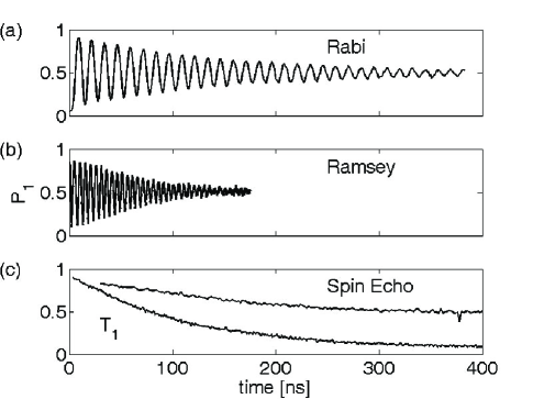
Experimental tests Cooper04 ; Simmonds04 on the redesigned phase qubit confirm the expected behavior. The number of splittings visible in the qubit spectroscopy is reduced roughly by an order of magnitude, yet their sizes are comparable to those of the conventional design (see Fig. 2). The visibility of the Rabi oscillations (Fig. 3(a)) is about and the decay is limited by the measured energy relaxation time of . Because of the small number of splittings, we are able to increase the Rabi oscillation period to about (limited by pulse shaping and the detuning of Steffen03 ), compared to a Rabi oscillation period using the conventional design Martinis05 .
From the data, we compute a measurement fidelity that is close to . This is an improvement of about compared with the measurement fidelity using the standard phase qubit design. Our observations confirm the prediction that measurement fidelity is reduced by sweeping through avoided level crossings during our measurement pulse Cooper04 . Half of the remaining loss in the measurement fidelity can be attributed to energy relaxation (as the measurement takes about ), while the remaining half can be attributed to a loss in signal due to sweeping through a few remaining junction resonances. Additional experimental data, including Ramsey fringes and a Spin Echo (Fig. 3(b) and (c)) are consistent with measured linewidths from the qubit spectroscopy as well as the energy relaxation time.
The energy relaxation of the qubit is limited by the SiNx shunting capacitor, which has a measured loss tangent of . With a qubit frequency GHz, we expect an energy relaxation of , which is close to the measured value. Further improvements in are possible by fabricating shunting capacitors with even lower loss tangents.
The demonstrated improvements in fidelity now enable state tomography, which is necessary for a full characterization of qubit states and gate operations. Typically, state tomography involves measuring an unknown quantum state in different basis sets to extract its location on the Bloch sphere. However, in our experiment it is more convenient to always measure in the and basis, and perform the basis change through single qubit rotations prior to measurement.
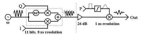
To perform tomography, we have designed and built a custom microwave pulse sequencer capable of producing microwave pulses with arbitrary amplitude and phase (see Fig. 4). We use an IQ mixer that adds, with separate amplitude control, the two quadrature components and of a continuous-wave microwave signal. The amplitude of both phases are controlled by an 11-bit digital to analog (DAC) converter that may be updated every . A second mixer performs gating and pulse shaping with a time resolution of .
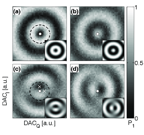
We use this microwave pulse sequencer to implement state tomography with two different techniques. The first method simply rotates an unknown Bloch vector over all rotation amplitudes and angles in the plane of the Bloch sphere prior to measuring the final state occupation probability of . From the resulting two-dimensional probability map, the direction of the Bloch vector can be simply computed from the amplitude and phase of the DAC values at maximum , and the Bloch vector length from the maximum contrast of .
In Fig. 5 we plot as a function of amplitude of the and components for several different initial states. In Fig. 5(a) the initial state is the ground state , and we observe generalized Rabi oscillations that are independent of the microwave phase, as expected. For the state of Fig. 5(b), the populations are inverted as compared to (a). In Fig. 5(c) the initial state is the superposition , which is pointing along the -direction on the Bloch sphere. As a result, rotations about the -direction (controlled by DACQ) will not affect the state. However, rotations along the -direction (controlled by DACI) rotate the state and result in Rabi oscillations. The state is similarly plotted in (d), and shows a rotation in the direction of oscillations as compared to (c). Theoretical predictions are shown in the insets of Fig. 5; small differences arise primarily from off-resonance effects of the state Steffen03 .
The data clearly shows this technique can be used to reconstruct an unknown quantum state for complete testing of one qubit. However, a more efficient and widely used technique makes use of the fact that any arbitrary single qubit density matrix can be described by where denotes the Pauli matrices, is the identity matrix, and are real coefficients Chuang98 ; Liu05 . Therefore, in order to reconstruct an unknown quantum state, we must identify the three-component vector .
The simplest approach measures the three components directly by performing three different read-out schemes. The first read-out is a simple measurement of the state occupation probability of , which measures the component. The second (third) read-out applies a rotation around the -direction (-direction), followed by a measurement of the occupation probability of , measuring the () components. Using the three measured occupation probabilities we can reconstruct the quantum state via a least squares fit and place it on the Bloch sphere. Experimentally, this technique is advantageous because it requires only three different read-out sequences instead of acquiring a two-dimensional map.
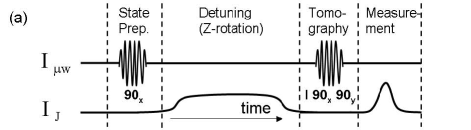
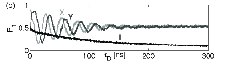
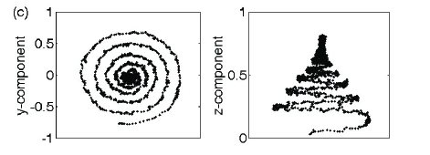
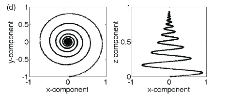
We use this state tomography to trace out the time evolution of the single qubit quantum state in a Ramsey type experiment, as shown in Fig. 6. In this sequence, we include a current pulse during free evolution to rotate the qubit state about the -axis. This rotation is observed experimentally, and dephasing causes the -component to shrink (Fig. 6c, left panel) and relax toward the ground state (Fig. 6c, right panel). These effects are confirmed by a theoretical model which includes energy relaxation and dephasing (see Fig. 6d). The main difference between the experiment and theory is that the length of the reconstructed vector of the first point is about instead of unity. The loss is explained by the measurement fidelity and a time delay of between the end of the detuning and the tomography pulses resulting in an additional loss. The loss due to reduced measurement fidelities can in principle be compensated by normalizing the data, but this was not done here for clarity.
In conclusion, we have introduced a new design for superconducting phase qubits that explicitly separates the capacitive from the inductive element of the Josephson junction. The number of TLS that couple to the qubit is reduced by an order of magnitude, improving the measurement fidelity to and enabling quantum state tomography. We believe that all aspects of our qubit’s performance may now be sufficient to demonstrate violations of Bell’s inequalities in coupled qubits. Furthermore, our results pave a clear path towards future improvements in decoherence through the fabrication of simple capacitors with lower dielectric loss.
We acknowledge Steve Waltman and NIST for support in building the microwave electronics. Devices were made at the UCSB and Cornell Nanofabrication Facilities, a part of the NSF funded NNIN network. N. K. acknowledges support of the Rothschild fellowship. This work was supported by ARDA under ARO grant W911NF-04-1-0204 and NSF under grant CCF-0507227.
References
- (1) Y.A. Pashkin et al., Nature 421, 823 (2003).
- (2) D. Vion et al., Science 296, 886 (2002).
- (3) E. Collin et al., Phys. Rev. Lett., 93, 157005 (2004)
- (4) I. Chiorescu et al., Science 299, 1869 (2003).
- (5) P. Bertet et al., cond-mat/0412485 [Phys. Rev. Lett., submitted] (2005).
- (6) A. Wallraff et al., Phys. Rev. Lett., 95, 060501 (2005).
- (7) J.M. Martinis, S. Nam, J. Aumentado, C. Urbina, Phys. Rev. Lett., 89, 117901 (2002)
- (8) R. McDermott et al., Science 307, 1299 (2005).
- (9) J.M. Martinis et al., Phys. Rev. Lett., 95, 210503 (2005).
- (10) D.J. Van Harlingen et al., Phys. Rev. B, 70, 064517 (2004)
- (11) F.C. Wellstood, C. Urbina, J. Clarke, Appl. Phys. Lett., 85, 22, 5296 (2004)
- (12) M. Mück et al., Appl. Phys. Lett., 86, 012510 (2005)
- (13) Previous work Martinis05 showed that coherence loss scales as , where is the average number of individual TLS that couple to the qubit. The quantity scales as the junction area multiplied by the largest splitting size , where is the total capacitance. Loss in coherence thus scales as .
- (14) K.B. Cooper et al, Phys. Rev. Lett., 93, 180401 (2004).
- (15) R.W. Simmonds, K.M. Lang, D.A. Hite, S. Nam, D.P. Pappas, J.M. Martinis, Phys. Rev. Lett., 93, 077003 (2004).
- (16) M. Steffen, J.M. Martinis, I.L. Chuang, Phys. Rev. B, 68, 224518 (2003)
- (17) I.L. Chuang, N. Gershenfeld, M.G. Kubinec, D.W. Leung, Proc. Roy. Soc. A, 454, 447 (1998)
- (18) Y. Liu, L.F. Wei, F. Nori, Phys. Rev. B, 72, 014547 (2005)
- (19) A new design allowed adiabatic changes in the bias current ; to be published.