Evaporation of an atomic beam on a material surface
Abstract
We report on the implementation of evaporative cooling of a magnetically guided beam by adsorption on a ceramic surface. We use a transverse magnetic field to shift locally the beam towards the surface, where atoms are selectively evaporated. With a 5 mm long ceramic piece, we gain a factor on the phase space density. Our results are consistent with a 100% efficiency of this evaporation process. The flexible implementation that we have demonstrated, combined with the very local action of the evaporation zone, makes this method particularly suited for the evaporative cooling of a beam.
pacs:
32.80.Pj, 03.75.PpSince its first demonstration for magnetically trapped atomic hydrogen hydrogen , evaporative cooling has proven to be a powerful technique to increase the phase-space density of trapped gases. It was used, in the case of alkali vapors, to reach the Bose-Einstein condensation (BEC) threshold rmpnobelbec . This cooling technique plays a central role in the rapidly expanding field of ultracold quantum degenerate gases. Evaporative cooling occurs when energetic atoms are removed from the cloud as a result of elastic collisions. Since these atoms belong to the high energy tail of the thermal distribution, the remaining trapped atoms collisionally equilibrate to a lower temperature.
As initially proposed and studied theoretically in Ref. Mandonnet00 , if a non-degenerate, but already slow and cold beam of particles, is injected into a magnetic guide where transverse evaporation takes place, quantum degeneracy can be achieved at the exit of the guide. Such a scheme transposes in the space domain what is usually done for trapped atoms in time, so that all operations leading to condensation are performed in parallel, resulting in a much larger expected output flux.
In recent experiments, evaporative cooling of a beam has been implemented by driving transitions to an untrapped state with radio-frequency prlrb2 or/and microwave lahaye05 fields. The drawback of these two methods lies in the range over which a radio-frequency antenna or a microwave horn effectively acts. On our experimental setup, atoms are affected by the field on a zone whose length is at least 20 cm. Such a range limits the number of evaporation zones that can be practically implemented. In addition, it turns out that it is quite difficult to ensure a 100% efficiency of the evaporation with those two methods, which strongly affects the possible gains on the phase space density and on the collision rate.
In this article we report on a much more local evaporation technique – the evaporation zone is 5 mm long. It relies on the elimination of atoms on a surface. This technique has been used in Ref. cornell to evaporatively cool atoms to Bose Einstein Condensation with a dielectric surface. We demonstrate here a possible implementation of this technique to a magnetically guided atomic beam, and discuss its prospects.
The experimental setup, described in detail in Refs. prlrb2 ; lahaye05 , allows for the generation of an intense and continuous beam of cold 87Rb atoms polarized in the state, and magnetically guided over 4.5 m. This beam results from the overlapping of packets of cold atoms injected into the magnetic guide at a rate of 5 per second. Each packet is prepared by loading an elongated magneto-optical trap (MOT) that collects atoms from a Zeeman slower zeemanslower in 100 ms. The packets are launched at a velocity of 1.1 m.s-1, towards the magnetic guide entrance, by a moving molasses technique launch .
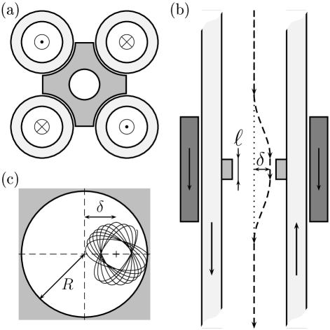
The guide, placed inside the vacuum system, consists of four parallel, water-cooled copper tubes, which are held together using 5 mm long ceramic pieces every 40 cm. The cross shape of the ceramic piece (see Fig. 1.a) permits to accommodate the four copper tube (outer diameter 6 mm, inner diameter 4 mm). Atoms propagate through a cylindrical hole of radius mm. The currents run are chosen with opposite sign for adjacent tubes in order to generate a two-dimensional quadrupole magnetic field configuration characterized by a transverse gradient G/cm, with a current of 320 A per tube. In addition we superimpose a longitudinal bias field G to avoid Majorana spin-flips losses lahaye05 . The resulting semi-linear confining potential reads:
| (1) |
where is the magnetic moment of an atom, and is the distance from the guide axis.
For a given transverse confinement, the beam is completely characterized by its flux , its temperature and its mean longitudinal velocity . The flux is on the order of atoms/s. The temperature of the guided beam is deduced from a radio-frequency (rf) spectroscopy technique prlrb2 . This technique allows for the determination of the temperature with an accuracy of typically 3% lahaye05 . For our parameters, we find K. With this flux, temperature and mean longitudinal velocity, the beam is clearly in the collisional regime prlrb2 .
To demonstrate the implementation of evaporation by using a ceramic surface, we have to remove atoms from the beam selectively in position. This is accomplished by the application of a transverse magnetic field that shifts the minimum of the transverse confinement towards the cylindrical edge of the ceramic surface (see Fig. 1.b). This magnetic field is generated by a pair of coils with a mean radius 45 mm and separated by a distance of 100 mm. Such a two-coils configuration is particularly well suited for our demonstration since it essentially results in a field perpendicular to the guide axis over the whole range of interest, the longitudinal component being negligible around the guide axis.

In presence of the coils field, the atoms are transversally shifted by . The confinement strength essentially remains unaffected in the range of parameters where the method has been used. We have checked that, in a zone without a ceramic piece, the application of the transverse magnetic field only results in a shift of the atomic beam. Indeed, even for as large as 2 mm, the flux and temperature of the beam remain constant within the accuracy of our measurements. This is indeed the first prerequisite to validate our protocol.
Qualitatively, as the measured thermal transverse size of the beam is at most of the order of the radius , we expect that when the line of minimum of energy has been shifted by the diameter of the hole in the ceramic (), no atoms remain. For a given displacement , the fraction of remaining atoms depends on the confining potential, the temperature, the radius of the ceramic and the mean longitudinal velocity of the atoms. Indeed, an atom with a low longitudinal velocity spends more time in the evaporation zone and increases its probability of being evaporated.
We have depicted on Fig. 2 the fraction of remaining atomic flux as a function of the displacement . Even after a shift by , no atoms remain. To understand quantitatively the shape of this evaporation curve, we have developed a Monte-Carlo numerical simulation. The initial positions and velocities of the particles are randomly chosen according to the thermal equilibrium distribution in the semi-linear potential (1). We use the experimental values for the bias field , the gradient , the mean velocity of the beam and the temperature . The motion of each atom is governed by the Hamiltonian , and calculated with a symplectic fourth-order algorithm symp , interatomic collisions are not taken into account. The surface of evaporation is a cylinder of radius and length mm. To account for the relative displacement between the atoms and the surface, the cylinder is shifted off axis by a quantity . Consequently, the evaporation criterium reads . In the numerical simulation, we assume a 100% efficiency of evaporation. This assumption is strongly supported by the excellent agreement between the simulation (Fig. 2, solid line) and the experimental points (squares). The only adjustable parameter in the simulated curve is a global shift on , which reveals that the ceramic piece is, in absence of transverse field, out-of-center by approximatively 60 m.

For a displacement mm and an upstream temperature of 640 K, we have measured the temperature 3 m downstream the ceramic piece. After such a distance the beam has completely rethermalized to the lower temperature 500 K. In combination with the measured 40% flux reduction (Fig. 2), we deduce a gain in phase space density of . This result is in good agreement with the prediction of our numerical simulation (see Fig. 3) where one can infer the downstream temperature and the gain in phase-space density by computing the remaining flux and energy per atom after the evaporation zone.
Unlike radio-frequency evaporation, this surface evaporation occurs only along one dimension in position space. One may wonder about the efficiency in terms of gain in phase space density and collision rate of this one-dimensional evaporation. However, each atom trajectory precesses around the center of symmetry axis since the confining potential is not harmonic but semi-linear (see Fig. 1.c). As a consequence, if an atom with adequate transverse energy and angular momentum spends a long time with respect to its oscillation period in the evaporation region, it will be evaporated, irrespective of its initial position. In other words, the real dimensionality of evaporation depends on the length of the surface. We have depicted on Fig. 3, the gain in phase space density that we deduce from our numerical simulation with our experimental parameters for a length of the ceramic piece equal respectively to 0.01 mm (a), 5 mm (b), 10 mm (c) and 50 mm (d). The gain in phase space density is clearly magnified if atoms spend a longer time in the evaporation zone. Indeed if the surface is long enough, all atomic trajectories reaching a distance from the minimum of the magnetic potential larger than are evaporated. One then realizes a true two-dimensional evaporation where all atoms above a given radius are evaporated epjd (solid line on Fig. 3).
With a succession of ceramic pieces, it is possible in principle to adjust in a very flexible way, using external magnetic fields, the degree of evaporation by deflecting locally the atom trajectories towards the surface. An alternative way would consist in decreasing the radius of the successive pieces placed in the ultra-high vacuum chamber which accommodates the magnetic guide. This technique is particularly well suited for experiments aiming at achieving a cw atom laser.
Acknowledgements.
We are indebted to Jean Dalibard for a careful reading of the manuscript. We acknowledge fruitful discussions with the ENS laser cooling group, and financial support from the Délégation Générale pour l’Armement. Z. W. acknowledges support from the European Marie Curie Grant MIF1-CT-2004-509423. G. R. acknowledges support from the Délégation Générale pour l’Armement.References
- (1) Unité de Recherche de l’Ecole Normale Supérieure et de l’Université Pierre et Marie Curie, associée au CNRS.
- (2) C. Lovelace, C. Mehanian, T. J. Tommila, and D. M. Lee, Nature (London) 318, 30 (1985); H. F. Hess, G. P. Kochanski, J. M. Doyle, N. Masuhara, D. Kleppner, and T. J. Greytak, Phys. Rev. Lett. 59, 672 (1987); N. Masuhara, J. M. Doyle, J. C. Sandberg, D. Kleppner, and T. J. Greytak, Phys. Rev. Lett. 61, 935 (1988).
- (3) E. A. Cornell and C. E. Wieman Rev. Mod. Phys. 74, 875 (2002); W. Ketterle, Rev. Mod. Phys. 74, 1131 (2002).
- (4) E. Mandonnet, A. Minguzzi, R. Dum, I. Carusotto, Y. Castin and J. Dalibard, Eur. Phys J. D 10, 9 (2000).
- (5) T. Lahaye, Z. Wang, G. Reinaudi, S. P. Rath, J. Dalibard and D. Guéry-Odelin, Phys. Rev. A 72, 033411 (2005).
- (6) T. Lahaye, J. M. Vogels, K. J. Günter, Z. Wang, J. Dalibard, and D. Guéry-Odelin, Phys. Rev. Lett. 93, 093003 (2004).
- (7) D. M. Harber, J. M. McGuirk, J. M. Obretch, and E. A. Cornell, J. Low Temp. Phys. 133, 229 (2003).
- (8) H. J. Metcalf and P. van der Straten, Laser Cooling and Trapping, (Springer-Verlag, New York, 1999).
- (9) A. Clairon, C. Salomon, S. Guellati. and W.D. Phillips, Europhys. Lett., 16, 165 (1991).
- (10) H. Yoshida, Celest. Mech. Dyn. Astron. 56, 27 (1993).
- (11) T. Lahaye and D. Guéry-Odelin, Eur. Phys. J. D 33, 67 (2005).