Transverse electric current induced by optically injected spin current in cross-shaped InGaAs/InAlAs system
Abstract
We examine electric response of a linearly polarized light normally shed on a cross-shaped quasi 2-dimensional InGaAs/InAlAs system with structure inversion asymmetry. The photo-excited conduction electrons carry a pure spin current with in-plane spin polarization due to the Rashba spin-orbit interaction. We use Landauer-Büttiker formalism to show that this spin current induces two inward or outward transverse charge currents, which are observable in experiments. This effect may serve as an experimental probe of certain types of spin current.
pacs:
72.25.-b, 75.47.-mSpin coherent transport of conduction electrons in semiconductor heterostructures is currently an emerging subject due to its possible application in a new generation of electronic devices Wolf01Science . There have been considerable efforts to achieve spin polarized current or pure spin current in semiconductors such as injection from ferromagnetic contact FM , quantum spin pump Watson03 , spin Hall effectSHE , and spin like Andreev reflection Wang05prl . Optical injection of spin current is largely based on the fact that the spin polarized carriers in conduction band can be injected in semiconductors via absorption of the circularly or linearly polarized light Ganichev ; Bhat05prl . While there are successful ways to inject or generate spin current, its detection is still a subtle problem. Despite the optical methods which indicated spin accumulation due to the spin current SHEexperiments , it is tempting to probe spin current by measuring its electric effects Hirsch99prl ; Zhang05arxiv ; Hankiewicz05prb ; Shen05prl . In this Letter, we theoretically study electric transverse current driven by an optically injected spin current in a two-dimensional electron gas of InGaAs/InAlAs with structure inversion asymmetry. A linearly polarized light pumps electrons from valence to conduction bands, which induces a pure spin current with in-plane polarization due to the spin orbit coupling. The Hall effect related to this spin current in a cross-shaped mesoscopic system is explored, which yields two measurable inward or outward electric transverse currents. By using the Landauer-Büttiker formalism we provide an estimate of the electric transverse current measurable in experiments.
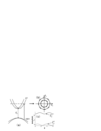
We begin with the optical injection of spin current in quasi-2D InGaAs/InAlAs with structural inversion asymmetry. The low energy band structure is well known and plotted schematically in Fig.1(a). The conduction electron can be described by an effective Hamiltonian,
| (1) |
where are the Pauli matrices, is the asymmetric confining potential perpendicular to the sample (-) plane, and is the strength of the Rashba spin-orbit coupling. The zero-field splitting of the conduction band arises because of the Rashba coupling, and electrons are spin polarized normal to the momentum in each subband, as shown in Fig.1(b). The electrons in the valence band near the point can be described by the Luttinger Hamiltonian,
| (2) |
where is the free electron mass, and are two Kohn-Luttinger parameters, which are taken to be and in this calculation Dai05arxiv , represent three spin- matrices. For simplicity, we approximate in Eqs.(1) and (2) by an infinite potential wall with a width of nm. The wave functions for the holes in the valence band can be obtained by a truncation method. We diagonalize in a truncated Hilbert space only including the lowest N basis states. In the present paper, we take , which is accurate enough for the lowest 4 hole subbands Dai05arxiv .
The process of optical excitation is schematically illustrated with the e1 and HH1 subbands in Fig.1. When a linearly polarized light is shed normally onto the sample plane, the electrons are pumped from the HH1 subband of the valence band to the e1 subband of the conduction band via direct optical absorption provided that the photon energy is higher than the band gap, i.e. . Due to the Rashba spin-orbit coupling, the conduction bands are split into two subbands as shown in Fig. 1(a) and (b). A photo-excited electron has an in-plane spin polarization perpendicular to its momentum, which induces a pure spin current. The spin current operators for electrons in the conduction band and holes in the valence band can be expressed in terms of the velocity and spin operators of electrons and holes, respectively, and , where and are the velocity operators for the conduction and valence bands, respectively. The total spin current from the photo-excited electrons and holes are,
| (3) |
where and are the density matrices for the conduction and valence bands, respectively. The density matrices that appear in Eq. (3) can be obtained in a relaxation time approximation. In the present study only the diagonal components of the density matrices are kept and the results can be written as transitionrate
| (4) | |||||
where is the relaxation time for electrons (holes) and is the transition matrix describing the direct optical transition between the conduction and valence subbands, which is caused by the external light. Under the dipole approximation, can be expressed by , where and are the and transformation matrices which diagonalize the Hamiltonian in Eqs.(1) and (2), respectively, and the matrix is the coupling matrix in the original basis of the row and column as
| (5) |
where is the polarization angle of the linearly polarized light and the factor is determined by the Bloch functions of electron and hole at the point. In this way the pure spin current is obtained as a function of the frequency and polarization of the light. The dominant component of the spin current flowing in the direction is , which is similar to the equilibrium current proposed by Rashba Rashba03prb . To calculate the spin current we adopt the parameters from a sample of InxGa1-xAs/In0.52Al0.48As Yang05 , with the Rashba coupling strength eVm, (, where is the speed of light,) the effective mass , the incident light power is mW with the wavelength nm. Also we extract from the experimental data Yang05 that , which is used in calculating the density matrices. Given a quantum well with the size to be , the induced current varies approximately with , as shown in Fig.1(c) with , the function of is fitted to be with and . And it is noticeable that there is also a non-vanishing component of the spin current, although it’s comparatively negligible.
We now turn to investigate the consequence of applying this in-plane polarized spin current to a cross-shaped mesoscopic system with the Rashba spin-orbit coupling, and it turns out that electric transverse currents will be induced in this case. Inevitably this is a situation reminiscent of the reciprocal version of the spin Hall effect proposed by Hirsch Hirsch99prl and Zhang et al Zhang05arxiv , in which a transverse current was predicted to arise when a spin current polarized perpendicular to the plane flows through the scattering region. And a general Onsager relation between the spin Hall conductance and the electric Hall conductance has been found in a similar condition Hankiewicz05prb . While the spin current is indeed a tensor, not a conventional vector, its spin polarization as well as the symmetries of the scattering spin-orbit coupling play key roles in generating the electric transverse current, which implies that for in-plane polarized spin current, the induced transverse currents may have a quite different character. Here we show this difference from the symmetry point of view, estimate the amplitude of transverse current numerically, and then propose an experiment to observe the transverse electric currents induced by the in-plane polarized spin current in our case.
In our proposal the whole setup is carved on an InGaAs/InAlAs heterojunction with a central scattering region and four leads for measurements, as shown in the inset of Fig. 2. The transverse leads (leads and ) and the scattering region should be masked to prevent from the light shining explicitly, while the longitudinal leads (leads and ) are opened to accept the linearly polarized light to generate the incident in-plane polarized spin current. By avoiding any possible interfaces of current injection, the spin current is expected to circulate in the direction without conventional spin injection problem. Under the Landauer-Büttiker formalism Buttiker86PRL ; Datta95 , which has been extensively used in the study of quantum transport in mesoscopic systems LBspinHall ; LBsymmetry , and will be applied to analyze the transverse currents in our case, we simulate the generation of the spin current and the measurement of the transverse currents by assuming a proper setting of the spin-dependent chemical potential related to each lead. In detail, if we denote the effective voltage related to spin polarization () at lead by , then we assume and . It should noted that can be oriented in , or direction (to consider either in-plane or perpendicular-to-plane polarized spin current), which will be denoted by or . Given this voltage setting, the symmetry properties of the currents will be fully presented by the spin-dependent transmission functions between the leads LBsymmetry , as we will see.

In each lead (assumed to be ideal and semi-infinite by convention) attached
to the central shaded region in the inset of Fig. 2, the wave function can
be expanded in terms of separate propagating modes, which are the
eigenstates in the lead. In , for example, the eigenstates are ,
where is the normalization constant, is the
eigenstate in the transverse dimension, is the spin
eigenstate with or and denotes the
mode is incoming or outgoing. The expansion coefficients of the actual wave
functions in terms of these eigenstates are known as the wave amplitudes , which are related by an unitary matrix and all the symmetries
of the transport properties in the system are embedded in this S-matrix. For
simplicity we assume that the quantum modes in opposite leads are
symmetrical, which means that for each mode with wave vector and
spin polarization in lead () there is a mode with the
same wave vector and spin polarization in lead (), and vice
versa. In the clean limit, the Hamiltonian with the Rashba spin-orbit
coupling term is obviously invariant under three unitary transformations,
i.e. commutes with the time-reversal operator , where is the complex-conjugate operator, and two combined operators and , where () denotes the mirror
reflection operator transforming ().
While the transformed eigenstates remain as eigenstates of the original
Hamiltonian, some of the amplitudes are transformed in the following ways:
under the transformation of ,
| (6) |
under the transformation of ,
| (7) |
where or , and is the counterpart of in its opposite lead. The phase factors are neglected in the above transformations because they will not be manifested in the following calculations of the transmission probabilities. The symmetries as well as the unitary condition impose constraints on the S-matrix, and thus on the transmission probability from mode to mode , which is defined as . For the time reversal symmetry , this yields
| (8) |
for the symmetry under ,
| (9) |
where or if , or otherwise. By summing up all the transmission probabilities between two leads with specific spin polarizations, the transmission functions , and the currents are obtained using the extended Büttiker formula Buttiker86PRL with the electric and spin current defined as and , respectively. Combining the symmetry-derived Eqs.(8) and (9) with the preceding voltage configuration, we find
| (10b) | |||
| (10d) | |||
| (10f) | |||
| It is clear now to see the difference between the transverse electric currents induced by a -direction polarized spin current and an in-plane polarized spin current, that is in the former case the transverse current is a truly circulating one, which can be naturally regarded as a reversed effect of the spin Hall effect Hirsch99prl ; Zhang05arxiv ; Hankiewicz05prb , whereas in our case of in-plane polarization, the transverse currents are flowing both inward or outward instead of circulating through the two transverse leads. Consequently this will make an essential difference in the measurements of the currents in such systems. To present a quantitative estimate of the induced currents, we make numerical calculations with the tight-binding approximation in this cross-shaped mesoscopic system, and the ratio of the induced electric transverse current to the spin current are plotted in Fig.2. Combined with the calculated value of the injected spin current, we notice that the induced current is about nA, which is large enough to be measured experimentally, while the small part of the spin current with spin polarization along axis does not contribute to the transverse currents. | |||
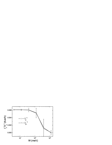
In practice, there are two major factors which will affect our conclusions, the disorder effect and the absence of the symmetry of leads we’ve assumed previously. The disorder breaks the symmetries of the system in a way as adding some random on-site potentials. Our numerical calculation with on-site potentials varying within , illustrated in Fig. 3, shows that despite the current approaching zero with increasing , the symmetry relations shown in Eq.(10b) and Eq.(10d) are well preserved in terms of the average values provided is not too large. This is reasonable and consistent with previous works LBspinHall . As for the absence of the symmetry of the quantum channels in the leads, we mimic its effect by modifying the width of each lead, and the calculations show that the profile of each current is retained with its value changed according to the modification of the channel number, which implies that within a limited range of asymmetry, our conclusions are still applicable.
In conclusion, a linearly polarized light may pump electrons from the valence band to the conduction band in InGaAs/InAlAs heterojunction, and the zero-field splitting of the conduction band with structural inversion asymmetry drives the photon-excited electrons and holes to form the spin current with in-plain spin polarization. The spin current was estimated by means of the electric-dipole approximation and relaxation time approximation. This mechanism provides a source of spin current to explore spin-dependent transport in mesoscopic systems. Furthermore, the Landauer-Büttiker formula is used to calculate the electric Hall currents while optical injection of spin current is empirically regarded as a source of spin-dependent potentials. As a result two inward or out electric transverse currents are observed. All parameters in our calculation are adopted from a realistic sample of InGaAs/InAlAs heterojunction. Thus the effect may serve as an experimental probe of in-plane polarized spin currents.
The authors thank J. Sinova for helpful discussions. This work was supported in part by the RGC of Hong Kong under Grant No. HKU 7039/05P.
References
- (1) S. A. Wolf et al, Science 294, 1488 (2001)
- (2) A. G. Aronov, Zh. Eksp. Teor. Fiz. 71, 370 (1976) [Sov. Phys. JETP 44, 193 (1976)]; M. Johnson and R. H. Silsbee, Phys. Rev. Lett. 55, 1790 (1985); for a review, see I. Zutic et al, Rev. Mod. Phys. 76, 323 (2004)
- (3) S. K. Watson et al, Phys. Rev. Lett. 91, 258301 (2003)
- (4) S. Murakami et al, Science 301, 1348 (2003); J. Sinova et al, Phys. Rev. Lett. 92, 126603 (2004); S. Q. Shen et al, ibid. 92, 256603 (2004)
- (5) B. Wang et al, Phys. Rev. Lett. 95, 086608 (2005)
- (6) S. D. Ganichev et al, Phys. Rev. Lett. 86, 4358 (2001); S. D. Ganichev et al, Nature 417, 153 (2002).
- (7) R. D. R. Bhat and J. E. Sipe, Phys. Rev. Lett. 85, 5432 (2000); R. D. R. Bhat et al, ibid. 94, 096603 (2005); E. Ya. Sherman et al, Appli. Phys. Lett. 86, 122103 (2005)
- (8) Y. K. Kato et al, Science 306, 1910 (2004); J. Wunderlich et al, Phys. Rev. Lett. 94, 047204 (2005)
- (9) J. E. Hirsch, Phys. Rev. Lett. 83, 1834 (1999)
- (10) P. Zhang et al, cond-mat/0503505
- (11) E. M. Hankiewicz et al, Phys. Rev. B 72, 155305 (2005)
- (12) S. Q. Shen, Phys. Rev. Lett. 95, 187203 (2005)
- (13) X. Dai et al, cond-mat/0507603
- (14) E. I. Rashba, Phys. Rev. B 68, 241315 (2003)
- (15) J. J. Sakurai, Modern Quantum Mechanics (Addison-Wesley, Reading, 1994)
- (16) J. Nitta et al, Phys. Rev. Lett. 78, 1335 (1997); C. L. Yang et al, unpublished.
- (17) M. Büttiker, Phys. Rev. Lett. 57, 1761 (1986)
- (18) S. Datta, Electronic transportin mesoscopic systems (Cambridge University Press, Cambridge, 1995)
- (19) L. Sheng et al, Phys. Rev. Lett. 94, 016602 (2005); B. K. Nikolic et al, Phys. Rev. B 72, 075361 (2005); E. M. Hankiewicz et al, ibid. 70, 241301(R) (2004); J. Li et al, ibid. 71, 241305(R) (2005)
- (20) T. P. Pareek, Phys. Rev. Lett. 92, 076601 (2004); F. Zhai and H. Q. Xu, ibid. 94, 246601 (2005)