Negative Refraction in Ferromagnet/Superconductor Superlattices
Abstract
Negative refraction, which reverses many fundamental aspects of classical optics, can be obtained in systems with negative magnetic permeability and negative dielectric permittivity. This Letter documents an experimental realization of negative refraction at millimeter waves, finite magnetic fields and cryogenic temperatures utilizing a multilayer stack of ferromagnetic and superconducting thin films. In the present case the superconducting YBa2Cu3O7 layers provide negative permittivity while negative permeability is achieved via ferromagnetic (La:Sr)MnO3 layers for frequencies and magnetic fields close to the ferromagnetic resonance. In these superlattices the refractive index can be switched between positive and negative regions using external magnetic field as tuning parameter.
pacs:
74.78.Fk, 78.67.Pt, 41.20.Jb, 76.50.+gOver the past centuries lenses were important tools to discover the fundamental laws of optics and even to develop an early understanding of the universe. Since then diffraction and reflection are well understood and belong to the basics of fundamental physics. Classical optics also sets a lower limit for the resolution of any optical device: The focus is limited by the wave length of light. However, in 1968 Veselago veselago proposed that a material with a negative index of refraction (NIR), i. e. with electric permittivity and magnetic permeability , would reverse all known optical properties pendry . Later on, the conditions leading to NIR have been extended to media with dissipation depine . In a negative refraction material (NRM) electromagnetic waves propagate in a direction opposite to that of the flow of energy. 30 years later this predictions have experimentally been confirmed smith ; shelby ; par ; houck ; fot ; cub ; parimi . Unfortunately, nature does not provide an adequate material and hence, metamaterials smith ; shelby ; par ; houck and photonic crystals fot ; cub ; parimi have been utilized as NRMs. Metamaterials are well-designed arrays of metallic posts yielding , interdispersed with an array of split-ring resonators revealing an effective negative magnetic permeability (). Photonic crystals are two- or three-dimensional arrays of periodic arrangements of dielectric or metallic elements.
One of the most outstanding predictions for materials with a NIR has been made by Pendry pendry : a NRM reveals a resolution beyond the diffraction limit and allows the construction of ideal lenses. Also this superlensing effect has been experimentally verified for a number of metamaterials at microwave frequencies lagarkov ; grbic and very recently even for optical frequencies fang .
In this Letter we demonstrate experimentally that a superlattice designed of subsequent thin ferromagnetic and superconducting layers also provides a negative index of refraction. In this metamaterial the superconducting layers of high- YBa2Cu3O7 (YBCO) provide the negative permittivity, while the ferromagnetic layers of the insulating manganite La0.89Sr0.11MnO3 (LSMO) reveal negative magnetic permeability close to the ferromagnetic resonance. This investigated structure is similar to the bilayer system suggested by Alù and Engheta alu , which has been analyzed in details by Lakhtakia and Krowne krowne showing the possibility of negative refraction.
LSMO/YBCO superlattices piotr2 were deposited on (100) (LaAlO3)0.3(Sr2LaAlTaO6)0.7 (LSAT) substrates by multitarget high-pressure sputtering piotr1 . Two targets with nominal composition of YBa2Cu3O7 and La0.98Sr0.11MnO3 were used for deposition. The thickness of different layers was controlled by the deposition times of the respective targets. Two samples from these targets have been prepared, with compositions [66 unit cells (uc) LSMO / 8 uc YBCO]8 and [33 uc LSMO / 8 uc YBCO]8. The observed properties of both compositions were qualitatively similar, except for a weaker magnetic signal of the latter sample (roughly a factor of two due to the lower LSMO content). Therefore, in the following only the results from the first sample will be shown. The superlattices were characterized using X-ray and SQUID-magnetization measurements. For both samples a clear diamagnetic signal (Meissner effect) has been observed at low temperatures. Characteristic susceptibility curves in the field-cooled (FC) and zero-field-cooled regime (ZFC) are shown in the upper panel of Fig. 1. From these data the ferromagnetic Curie-temperature K has been derived and from the magnetization curves the effective magnetic moment per manganese ion can be estimated as , denoting the Bohr’s magneton.
The dynamic experiments in the frequency range 0.06 THz 0.5 THz have been carried out in transmittance experiments using a Mach-Zehnder interferometer pronin . Temperature- and magnetic field-dependent experiments have been carried out in a split-coil magnet providing magnetic fields up to 7 T and temperatures 1.8 K 300 K. This arrangement allows to investigate the transmittance and phase shift of the plane parallel samples as function of frequency, temperature, and external magnetic field. The effective permittivity and permeability of the superlattice have been calculated from these quantities using the Fresnel optical equation for the complex transmission coefficient of the plane-parallel plate born :
| (1) |
Here is is the reflection amplitude at the air-sample interface, is the “pure” transmission amplitude, and are the (complex) dielectric permittivity and magnetic permeability of the sample, respectively, is the sample thickness, and the radiation wavelength. The effective conductivity of the superlattices is obtained via , where is the permittivity of vacuum and the angular frequency. Eq. (1) is written in the approximation neglecting the properties of the substrate. During the experiments the full expression born has been used, which in most cases leads to results closely similar to Eq. (1) and is omitted here for simplicity. The properties of the LSAT substrate were measured in a separate experiment and could well be approximated by a frequency-independent refractive index .
In the THz frequency range and in the absence of the external magnetic field both YBCO and LSMO are non-magnetic in good approximation and therefore can be used in calculations for . Substantial deviations from can be expected in the vicinity of the ferromagnetic mode in LSMO only spin and are strongly magnetic field dependent. On the contrary, the dielectric permittivity is only weakly field-dependent and can be accounted for using an additional linear term. This procedure allows to separate the contributions of the dielectric permittivity and magnetic permeability in Eq. (1) combining zero-field data with the results in external magnetic fields.

Lower panel: Right scale: resistivity of the superlattices at a frequency of 90 GHz. Left scale: superconducting penetration depth. Dashed lines indicate the transition temperatures between different phases, SC - superconducting, M - metallic, FM - ferromagnetic, and PM - paramagnetic.
Lower panel of Fig. 1 shows the effective dynamic resistivity Re of the LSMO/YBCO superlattice measured at a frequency 90 GHz. The superlattice has a total thickness of d = 284 nm. In the normally-conducting state, 90 K, the resistance of the superlattice is only weakly temperature dependent and is determined by the metallic conductivity of YBCO. The real part of the dynamic conductivity reveals no measurable frequency dependence in the frequency range of the experiments and the imaginary part is zero within experimental uncertainties. Both properties are characteristic for genuine metallic behavior and have been observed in pure YBCO films using the same technique pimenov . The microwave resistivity is rapidly suppressed below the superconducting transition temperature 87 K, qualitatively resembling the behavior of the dc resistance (not shown). The left scale of the lower panel of Fig. 1 shows the superconducting penetration depth of the superlattice, obtained via . Here is the permeability of vacuum. At low temperatures the imaginary part of the conductivity is inversely proportional to the frequency, which warrants the frequency-independence of the penetration depth and is the characteristic feature of the superconducting state.
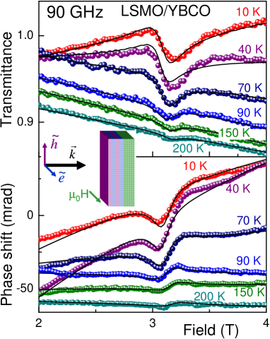
Figure 2 represents the magnetic field-dependence of the relative transmittance (upper panel) and the phase shift (lower panel) of the LSMO/YBCO superlattice at a frequency of 90 GHz. A ferromagnetic resonance (FMR) close to 3.1 T is clearly observed for all temperatures. Only at 200 K the intensity of the observed mode is just above the noise-level of the spectrometer. The spectra have been measured in Voigt geometry zvezdin , i.e. with the static magnetic field within the sample-plane. The geometry of the magnetic field-dependent experiment is shown as inset in Fig. 2. In addition to the sharp line of the ferromagnetic resonance, both transmittance and phase-shift reveal a weak overall field-dependence. This behavior corresponds to the high-frequency magnetoresistance of the superconductor/ferromagnet superlattices and is most pronounced in the superconducting state. The absolute value of this effect is of the order , much weaker than the dc-magnetoresistance with changes of the order of pena . The high-frequency magnetoresistance can be formally ascribed to the partial weakening of superconductivity in the external magnetic field and is beyond the scope of this work.
The solid lines in Fig. 2 have been calculated assuming a Lorentz shape of the ferromagnetic line, i.e. the magnetic permeability of a ferromagnet was taken as:
| (2) |
Here , and are the resonance field, width and magnetic contribution of the ferromagnetic line, respectively. The field dependence of complex conductivity has been accounted for assuming a linear magnetoresistance effect and has been obtained from the data far off the resonance position. Within the experimental uncertainties the width and the position of the ferromagnetic line are approximately temperature-independent with T and T. In the metallic temperature range 90 K the intensity of the line qualitatively follows the magnetization from (200 K) = 0.2 to (90 K) = 0.4. This is in agreement with the expectation of a ferromagnet , where is the static magnetization. Below the superconducting transition the intensity decreases with temperature, which probably results from the screening due to the onset of the superconductivity.
The form of the FMR line differs qualitatively in the metallic and the superconducting states. For example, at 90 K a symmetric dip in the transmittance and a resonance-like step in the phase-shift are fingerprints of a conventional resonance-line. At low temperature and in the superconducting state the line is highly asymmetric, and the form of transmittance and phase-shift curves have interchanged: at 10 K a dip appears in the phase-shift and an asymmetric step in the transmittance.
The strength of the ferromagnetic mode in the superconducting state leads to negative values of the magnetic permeability close to the resonance field chui . At the same time, the dielectric permittivity of a superconductor Re is large and negative (here is the permittivity of vacuum). Hence, the situation occurs, where both and are negative, corresponding to the Veselago’s criteria for a negative refractive index. In this case special care has to be taken in calculating the refractive index and the transmittance of the sample because the correct sign of the refractive index in the expression is not a priori evident. However, due to a continuous transition from the regions between negative and positive refractive indices, realized in our experiment, the question of the sign of the square-root is solved automatically.
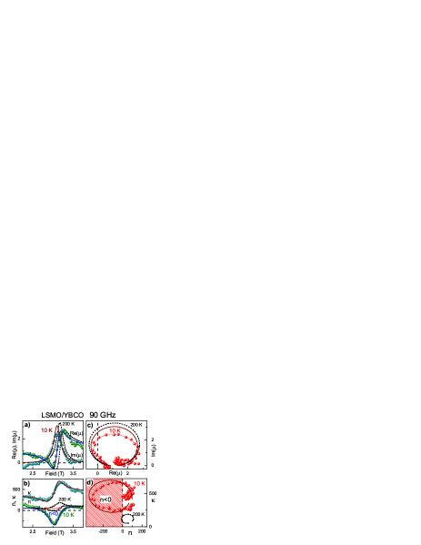
In addition to the fits of the experimental spectra of FMR, the field dependence of the magnetic permeability and the refractive index can directly be calculated from the data of Fig. 2. The calculated permeability ( Re(), Im()) vs. magnetic field is shown in Fig. 3a and the data are re-plotted in the complex plane in Fig. 3c. In this calculation we assumed that the complex conductivity in the vicinity of the FMR line depends linearly upon the magnetic field. The symbols in Figs. 3a-d represent the experimental data which are compared with the Lorentzian line-shape given by solid lines. As is clearly documented in Fig. 3a, the FMR mode is strong enough to produce a region with negative permeability between 2.9 T and 3.1 T. In combination with the negative dielectric permittivity of the superconductor, (10 K) , this leads to a substantial region with a negative refractive index (Fig. 3b,d). For comparison, the dashed lines in Fig. 3 show the results obtained at 200 K. At this temperature the dielectric permittivity is characteristic for a metal (200 K) and the resulting curve of the refractive index predominantly corresponds to .
Finally, the requirement of cryogenic temperatures and high magnetic fields hampers possible applications of the ferromagnet/superconductor multilayers. However, the absolute values of the external magnetic field can be reduced in the same system decreasing the frequency of the experiment. Substitution of a ferromagnet by an antiferromagnet with narrow line of the antiferromagnetic resonance may completely remove the necessity of the external magnetic fields. The way to increase the working temperature of the multilayers could be the substitution of the superconductor by a good metal revealing negative permittivity.
In conclusion, we have shown experimentally that a region of negative refractive index can be realized in superlattices of superconducting and ferromagnetic layers in the superconducting state close to the ferromagnetic resonance. Compared to metamaterials based on the metallic rods and split-ring resonators these results open another way to construct materials with negative refraction. In the superconductor/ferromagnet superlattices the refractive index can be switched between positive and negative regions using an external magnetic field as a tuning parameter
This work was supported by BMBF (13N6917/0 - EKM), DFG (SFB484 - Augsburg), US DoE, NSF-DMR-0302617, MaNP, and Polish Committee for Scientific Research (2006-2008).
References
- (1) V. G. Veselago, Sov. Phys. Uspekhi 10, 509 (1968).
- (2) J. B. Pendry, Phys. Rev. Lett. 85, 3966 (2000).
- (3) R. A. Depine and A. Lakhtakia, Microw. Opt. Technol. Lett. 41 315 (2004); M. W. McCall, A. Lakhtakia, and W. S. Weiglhofer, Eur. J. Phys. (UK) 23, 353 (2002).
- (4) D. R. Smith, W. J. Padilla, D. C. Vier, S. C. Nemat-Nasser, and S.Schultz, Phys. Rev. Lett. 84, 4184 (2000).
- (5) R. A. Shelby, D.R. Smith, and S. Schultz, Science 292, 77 (2001).
- (6) C. G. Parazzoli, R. B. Greegor, K. Li, B. E. C. Koltenbah, and M. Tanielian, Phys. Rev. Lett. 90, 107401 (2003).
- (7) A. A. Houck, J. B. Brock, and I. L. Chuang, Phys. Rev. Lett. 90, 137401 (2003).
- (8) S. Foteinopoulou, E. N. Economou, and C. M. Soukoulis, Phys. Rev. Lett. 90, 107402 (2003).
- (9) E. Cubukcu, K. Aydin, E. Ozbay, S. Foteinopoulou, and C.M. Soukoulis, Nature 423, 604 (2003).
- (10) P. V. Parimi, W. T. Lu, P. Vodo, and S. Sridhar, Nature 426, 404 (2003).
- (11) A. N. Lagarkov and V. N. Kissel, Phys. Rev. Lett. 92, 077401 (2004).
- (12) A. Grbic and G. V. Eleftheriades, Phys. Rev. Lett. 92, 117403 (2004).
- (13) N. Fang, H. Lee, C. Sun, and X. Zhang, Science 308, 534 (2005).
- (14) A. Alù and N. Engheta, IEEE Trans. Antennas Propag. 51, 2558 (2003); J. Appl. Phys. 97, 093340 (2005).
- (15) A. Lakhtakia and C. M. Krowne, Optik (Germany) 114, 305 (2003).
- (16) P. Przyslupski et al., Phys. Rev. B 69, 134428 (2004); J.Appl.Phys 95, 2906(2004).
- (17) P. Przyslupski, S. Kolesnik, E. Dynowska, S. T. Koskiewicz, and M. Sawicki, IEEE Trans. Appl. Supercond. 7, 2192 (1997).
- (18) A. V. Pronin et al., Phys. Rev. B 57, 14416 (1998); A. Pimenov et al., Phys. Rev. B. 72, 035131 (2005).
- (19) M. Born and E. Wolf, Principles of optics (Pergamon, Oxford, 1986).
- (20) D. Ivannikov et al., Phys. Rev. B 65, 214422 (2002).
- (21) A. Pimenov, A. Loidl, G. Jakob, and H. Adrian, Phys. Rev. B 59, 4390 (1999); 61, 7039 (2000).
- (22) A. K. Zvezdin and V. A. Kotov, Modern Magnetooptics and Magnetooptical Materials (Inst. of Physics Publ., Bristol, 1997).
- (23) V.Peña et al., Phys. Rev. Lett. 94, 057002 (2005).
- (24) S. T. Chui and L. Hu, Phys. Rev. B 65, 144407 (2002).