Switching of sub-m sized, antiferromagnetically coupled CoFeB/Ru/CoFeB trilayers
Abstract
This work reports on the magnetic reversal of sub-m sized elements consisting of an CoFeB/Ru/CoFeB artificial ferrimagnet (AFi). The elements were patterned into ellipses having a width of approximately 250 to 270nm and a varying aspect ratio between 1.3 and 8. The coercivity was found to decrease with an increasing imbalance of the magnetic moment of the two antiferromagnetically coupled layers and is therefore strongly affected by an increase of effective anisotropy due to the antiferromagnetic coupling of the two layers. With respect to a single layer of amorphous CoFeB, patterned in comparable elements, the AFi has an increased coercivity. Switching asteroids comparable to single layers were only observed for samples with a high net moment.
pacs:
75.75.+a,75.50.KjI Introduction
Magnetic tunnel junctions (MTJ) have gained considerable interest in recent years due to their high potential in various applications, e.g. as reads heads Ho01 , angle Berg99 or strain sensors Loehndorf02a and as programmable resistance in data storage (MRAM) Gallagher97 or even magnetic logic devices Richter02a .
The underlaying concept is a spin valve consisting of a hard magnetic reference electrode separated from the soft magnetic sense or storage layer by a tunnel barrier like Al2O3. The reference layer usually is an artificial ferrimagnet (AFi) exchange biased by a natural antiferromagnet, in which the AFi consists of two ferromagnetic layers coupled antiparallel via a thin non-magnetic spacer. For the soft electrode, mostly single layers of polycrystalline material, e.g NiFe and CoFe, have been used Koch98 . Recently, soft electrodes of polycrystalline AFis, based on ferromagnetic materials like CoFe and NiFe, have been investigated. They show a further reduction of the stray field due to the reduced net moment, smaller switching field distribution Sousa02 and an easier establishment of a single domain structure in patterned elements with small aspect ratio Tezuka03a .
Additionally, the concept of an AFi allows one to further adjust the magnetic properties of the soft layer. Compared to the coercivity of a continuous single layer, , the coercivity of the AFi, , is enhanced by a factor :
| (1) |
where and are the saturation magnetization and the thickness of the two composite ferromagnetic layers.Berg96 As shown before for unpatterned AFi films consisting of two amorphous, ferromagnetic CoFeB layers, separated by a thin Ru spacer, the coercivity can be tailored in a wide range and is approximately by a factor of nine smaller than in systems of polycrystalline CoFe/Ru/CoFe.Wiese05 Furthermore the coupling of the amorphous CoFeB-AFi shows an oscillating behavior in dependence of the thickness of the nonmagnetic Ru spacer and achieves a coupling strength of the order of at the second antiferromagnetic maximum, which is about a factor of ten smaller than in polycrystalline CoFe/Ru/CoFe trilayers.Wiese04
It was the purpose of this study to investigate the switching behavior of the amorphous CoFeB-AFi at sub-m sizes, where additional shape anisotropy and the magnetostatic edge coupling have to be taken into account. These contributions lead to an effective anisotropy which is for patterned elements different from the anisotropy of continuous films (eqn. 1).
As the amorphous alloy we chose Co60Fe20B20 due to a high tunnel magnetoresistance (TMR) Wang04 and an enhanced temperature stability of the TMR Dimopoulos04 . A thin Ru spacer was used to mediate the coupling between the two ferromagnetic layers of the AFi.
| sample | system | J | ||
|---|---|---|---|---|
| A | CoFeB 3.5 / Ru 0.95 / CoFeB 3 | 7.7 | 29.8 | -0.06 |
| B | CoFeB 4.0 / Ru 0.95 / CoFeB 3 | 5.1 | 26.3 | -0.06 |
| C | CoFeB 4.5 / Ru 0.95 / CoFeB 3 | 3.7 | 23.9 | -0.06 |
| D | CoFeB 4 |
II Experimental
Samples have been deposited by magnetron sputtering on thermally oxidized SiO2 wafers at a base pressure of mbar. A magnetic field of approximately 4 kA/m was applied during deposition in order to induce the easy axis in the magnetic layers. The AFi was grown on a 1.2 nm thick Al layer, oxidized in an Ar/O2 plasma for 0.8 min without breaking the vacuum, to have similar growth conditions as in a MTJ. In order to investigate the switching behavior in dependence on the Q-value, three different samples have been prepared where the thickness of the ferromagnetic layer in contact with the Al2O3 layer, and thus the net magnetic moment, has been varied (see table 1, samples A to C). Additional a single CoFeB layers with a thickness of 4 nm (sample D) has been deposited for comparison. All samples were capped with a Ta layer to protect the multilayers from oxidation.
The samples have been patterned by a single step e-beam lithography and Ar-ion etching process. For lithography a positive e-beam resist was used, leading to patterns with a small edge roughness and high reproducibility across the whole array. On each sample different arrays of ellipses with a nominal width, , of 250nm and varying length, , have been defined, leading to different aspect ratios, , between 1.3 and 8. The lateral distances have been chosen three times the dimension of the elements, and therefore a dipolar coupling between the individual ellipses of an array can be neglected.Abraham_mmm04 Each of the arrays had the dimension of . After the arrays have been coated by a Ta layer of appropriate thickness (ranging from 8 to 15nm), the capping was removed in a lift-off process in a bath of solvent under application of ultrasonic agitation. During etching with a 80 Ar ion current the samples were tilted by approximately 30 degrees and rotated to obtain a uniform etch profile over the sample. The etching depth was monitored by a secondary ion mass spectrometer (SIMS) attached to the etching facility.
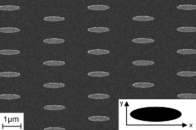
The sizes and the uniformity of all patterns have been characterized by scanning electron microscopy (SEM) after the patterning process. The SEM image in figure 1 shows one of the arrays of sample D with ellipses in the size of , confirming the high uniformity of the patterns. The width for samples with small aspect ratios () varied between 250 and 270nm. Due to a tendency of over-exposure, ellipses with larger aspect ratios show a slightly larger widths of approximately 300nm.
After patterning all samples have been field annealed for 20min. at 150 and applied parallel to the long axis of the ellipses using a vacuum annealing furnance. Magnetization loops of all arrays have been taken by a commercial magneto-optical Kerr effect magnetometer (MOKE) with a typical spot diameter of 4m.NanoMOKE
III Results and Discussion
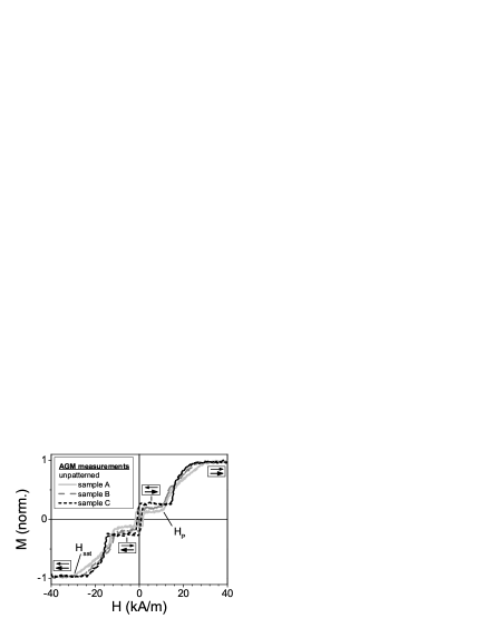
A room temperature magnetization curve, , of the antiferromagnetically (AF) coupled systems is shown in figure 2. From the loops, obtained by alternating gradient field magnetometery (AGM), one can extract the saturation field, , the total, , and the net magnetic moment, , allowing to calculate the measured Q-value, , the individual magnetization of the layers, , and the coupling energy Berg96
| (2) |
The coupling is for all investigated AFi samples. The values are in accordance to the oscillating coupling in dependence on the Ru spacer thickness around the second antiferromagnetic maximum as presented elsewhere.Wiese04 The measured Q-values vary between 3.7 and 7.7 for the investigated AFi samples, and are significantly smaller than the value, , calculated from the nominal thickness of the ferromagnetic layers. This discrepancy is supposed to result from a thicker magnetically dead layer of the upper CoFeB layer in comparison to the bottom layer. Since the samples are well protected from oxidation, as confirmed by Auger depth profiling, this would indicate a stronger intermixing of the upper CoFeB interfaces. All data extracted from the AGM measurements are given in table 1.
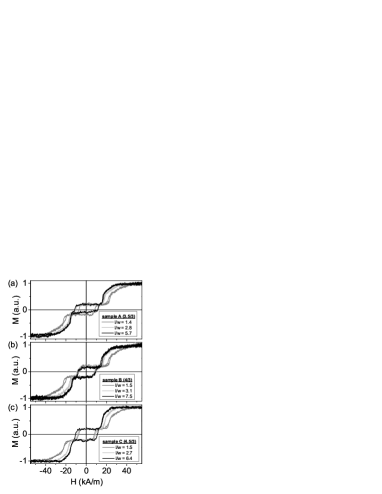
Figure 3 shows the magnetization loops of patterned arrays of all AFi samples as obtained by MOKE measurements. The strong AF coupling is maintained after the patterning and annealing steps. Additionally, the saturation field is increasing with decreasing aspect ratio (i.e. length or size) of the ellipses, due to an increase in stray field coupling between the layers within the AFi system. For large aspect ratios achieves the values of the unpatterned samples.
The saturation field can be expressed by two contributions, one originating from the antiferromagnetic interlayer coupling, the other resulting from the stray field coupling. Whereas the first should depend on , as derived from eqn. 2, the latter should depend on ,Sun01 where is the total thickness of the AFi. The second contribution only depends on the demagnetization factor , since the -components in case of an AF coupled system are compensated for external fields larger than the plateau field, . Since the width of the elements was hold constant for the investigated samples, the dependence of on the sample geometry is only given by the demagnetization factorHubert98
| (3) |
This model is fitted to the measured data as shown in figure 4(a). The fitting shows a high accordance between the experimental data and the model, thus verifying the dependence of the saturation field on for small aspect ratios. From the fitting parameters one can further extract the saturation field for an infinite elongated ellipse to 28.6 kA/m for sample A, 24.2 kA/m for sample B and 22.8 kA/m for sample C, respectively. This values are in good agreement to the measured saturation fields at the unpatterned AFi samples given by the interlayer coupling (see table 1).
For external fields smaller than , the AF coupling remains stable. As can be seen from figure 3, the AFi should reverse its magnetization like a single layer sample with a reduced net moment and enhanced effective anisotropy. Therefore it is possible to measure minor magnetization loops in a small field window ( to kA/m, depending on of the sample) and extract the coercivity, , of the arrays (see figure 4(b)).
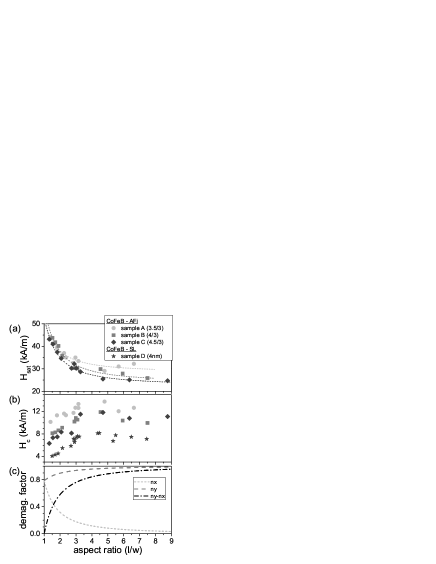
For small aspect ratios (), increases with by approximately 3.5 kA/m and remains constant for large aspect ratios (see figure 4(b)). The slight decrease in coercivity for the largest aspect ratios is most likely attributed to the slightly larger width of the ellipses. This behavior of the coercivity vs. aspect ratio holds also for the single layer sample. The increase of for small aspect ratios is caused by the increase in shape anisotropy, which for an ellipse is given bySun01
| (4) |
where the demagnetization factor () depends on the aspect ratio. Therefore the experimental results of figure 4 (b) are in qualitative accordance with the () dependence on aspect ratio (see figure 4(c)). Deviations from the calculated dependence for large aspect ratios are likely to result from micromagnetic differences: Small elements are stabilized by a non vanishing stray field, arising from the magnetic poles of the elements. These stray fields stabilize the overall magnetization of the elements, so that the reversal can be more accurately approximated by a single domain mechanism. For large aspect ratios the magnetic poles are larger separated, thus minimizing the stray field coupling and as a result a nucleation driven magnetization reversal, most likely initiated by edge domains, is more favourable, leading to a almost constant coercivity.Meyners03
Unlike elliptic elements with a single ferromagnetic layer, the coercivity of the patterned AFi samples does not scale proportional to the net magnetic moment. With higher net moment, the coercivity is decreasing, but remaining always larger than for elements of a 4nm thick single layer. The reason is a superposition of the effective anisotropy due to the AF coupling (), as expressed by eqn. 1 for the unpatterned films, and the dependence of coercivity on the net magnetic moment as described by eqn. 4 (). Overall the influence of the AF coupling is dominating for the investigated CoFeB AFis and the coercivity is increased by approximately a factor of 1.4 when decreasing the net thickness of the AFi, and therefore the net moment, from 1.5 to 0.5nm.
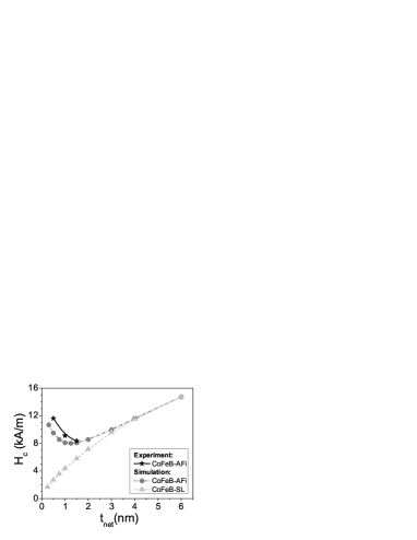
The dependence of coercivity on the net thickness, , of the AFi and for single layer samples with layer thicknesses of have been simulated within a micromagnetic model using Landau-Lifshitz-Gilbert equations (see figure 5).Scheinfein For the simulation of the AFis the thickness of the second FM layer, , was varied between 3.5 and 6nm, whereas the thickness of the first FM layer was kept fixed to , and the thickness of the nonmagnetic spacer was chosen to 1nm. The saturation moment of the FM layers were assumed to , the uniaxial anisotropy to , the exchange stiffness constant to and for the AF coupling constant to . The coercivity of the simulated elliptic AFi elements of decreases with net thickness for nm, and increases for larger , asymptotically reaching the values of the single layer coercivity. The experimental data of the AFi arrays with the same geometry show a similiar behavior, therefore verifying the above described model for the samples under study.
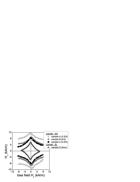
Figure 6 shows the bias field dependence of the coercivity for samples patterned with an aspect ratio of . Due to the increase of effective anisotropy with the Q-value (and therefore basically with the inverse net magnetic moment), the asteroid gets stretched along the hard axis field. If used in a conventional writing scheme as a soft magnetic electrode for applications like MRAM or magnetic logic, the broad asteroid shape of the AFi storage layer cells limits the choice of Q-value due to field limitations, reducing the proposed advantages of an AFi structure as reported by others.Sousa02 ; Tezuka03a
IV Conclusion
The AFi based on an amorphous CoFeB alloy shows a strong increase in the effective ansiotropy due to the AF coupling, mediated by a thin Ru interlayer and by the stray field coupling, respectively. This is reflected by a higher coercivity and an increase of the asteroid width compared to a single CoFeB layer. The dependence of the switching field on the net magnetic moment can not be explicitely explained within the model that considers the AFi as a rigid ferromagnetic layer with a reduced moment. One has further to take into account the increase of effective anisotropy, which basically scales with the inverse net moment for the investigated combinations of layer thicknesses. This last factor appears to be dominating in the system under study and leads to the decrease of coercivity with net moment. Finally, it has been found, that the saturation field of the patterned AFis is decreasing with larger aspect ratio and is asymptotically reaching the saturation field of the unpatterned films. The origin for this behavior for small aspect ratios can be found in the additional contribution of the stray field coupling of the two ferromagnetic layers within the AFi. Therefore the antiparallel alignment of the system is additionally favoured by the stray field coupling, depending basically on the demagnetization factor vs. aspect ratio.
Acknowledgments
The authors wish to thank J. Bangert and G. Gieres for fruitful discussions, H. Mai and K. Rott for experimental support. Financial support of the German Ministry for Education and Research is gratefully acknowledged (Grant no. 13N8208).
References
- (1) M.K. Ho, C.H. Tsang, R.E. Fontana, S.S.P. Parkin, K.J. Carey, T. Pan, S. MacDonald, P.C. Arnett, and J.O. Moore, IEEE Trans. Magn. 37, 1691 (2001)
- (2) H.A.M. van den Berg, J. Altmann, L. Bär, G. Gieres, R. Kinder, G. Rupp, M. Vieth, and J. Wecker, IEEE Trans. Magn. 35, 2892 (1999)
- (3) M. Löhndorf, T. Duenas, M. Tewes, E. Quandt, M. Rührig, and J. Wecker , Appl. Phys. Lett. 81, 313 (2002)
- (4) W.J. Gallagher, S.S.P. Parkin, Y. Lu, X.P. Bian, A. Marley, K.P. Roche, R.A. Altman, S.A. Rishton, C. Jahnes, T.M. Shaw, and G. Xiao, J. Appl. Phys. 81, 3741 (1997)
- (5) R. Richter, L. Bär, J. Wecker, and G. Reiss, Appl. Phys. Lett. 80, 1291 (2002)
- (6) R.H. Koch, J.G. Deak, D.W. Abraham, P.L. Trouilloud, R.A. Altman, Y. Lu, W.J. Gallagher, R.E. Scheuerlein, K.P. Roche, and S.S.P. Parkin, Phys. Rev. Lett. 81, 4512 (1998)
- (7) R.C. Sousa, Z. Zhang, and P.P. Freitas, J. Appl. Phys. 91, 7700 (2002)
- (8) N. Tezuka, N. Koike, K. Inomata, and S. Sugimoto, J. Appl. Phys. 93, 7441 (2003)
- (9) H.A.M van den Berg, W. Clemens, G. Gieres, G. Rupp, and M. Vieth , IEEE Trans. Magn. 32, 4624 (1996)
- (10) N. Wiese, T. Dimopoulos, M. Rührig, J. Wecker, H. Brückl, and G. Reiss, J. Magn. Magn. Mater. 290-291, 1427 (2005)
- (11) N. Wiese, T. Dimopoulos, M. Rührig, J. Wecker, H. Brückl, and G. Reiss, Appl. Phys. Lett. 85, 2020 (2004)
- (12) D. Wang, C. Nordman, J. Daughton, Z. Qian, and J. Fink, IEEE Trans Magn 40, 2269 (2004)
- (13) T. Dimopoulos, N. Wiese, G. Gieres, J. Wecker and M.D. Sacher, J. Appl. Phys. 96, 6382 (2004)
- (14) D.W. Abraham, and Y. Lu, J. Appl. Phys. 98, 023902 (2005)
- (15) for detailed specification of the NanoMOKE2™system look at the website of Durham Magneto Optics Ltd., http://durhammagnetooptics.com
- (16) J.Z. Sun, J.C. Slonczewski, P.L. Trouilloud, D. Abraham, I. Bacchus, W.J. Gallagher, J. Hummel, Y. Lu, G. Wright, S.S.P. Parkin, and R.H. Koch, Appl. Phys. Lett. 78, 4004 (2001)
- (17) A. Hubert, R. Schäfer, Magnetic Domains, The Analysis of Magnetic Microstructures, Springer (1998)
- (18) D. Meyners, H. Brückl, and G. Reiss, J. Appl. Phys. 93, 2676 (2003)
- (19) The commercial available micromagnetic program (LLG Micromagnetics Simulator™) developed by M.R. Scheinfein was used, see http://llgmicro.home.mindspring.com