Composite domain walls in flat nanomagnets: the magnetostatic limit
Abstract
We discuss the structure of the so-called “vortex” domain walls in soft magnetic nanoparticles. A wall of this kind is a composite object consisting of three elementary topological defects: two edge defects with winding numbers and a vortex with a winding number between them. We provide a qualitative model accounting for the energetics of such a domain wall.
Magnetic nanoparticles generate considerable interest as prospective building blocks for nonvolatile random-access memory Zhu et al. (2000). Storing of information bits is made possible by the existence of two (or more) stable magnetic configurations. Switching between the two stable states can be achieved by applying an external magnetic field or by injecting current. In either case the switching process proceeds through the formation of complex transient patterns of magnetization Zhu et al. (2004). Building fast and reliable magnetic memory thus requires a thorough understanding of magnetization dynamics in these nanomagnets.
In magnetic nanoparticles with the geometry of strips and rings the switching creates domains in which the magnetization is forced by the magnetostatic forces to be parallel to the edge. These domains grow and shrink at the expense of one another until one of them occupies the entire sample Zhu et al. (2004); Kläui et al. (2003). This process can also be viewed as the creation, propagation, and annihilation of domain walls. Thus the question of local stability and dynamics of the magnetic configurations can be answered by studying the static and dynamic properties of domain walls.
Domain walls in submicron rings and strips have a considerably complex structure. For instance, McMichael and Donahue McMichael and Donahue (1997) have observed, among others, configurations termed “transverse” and “vortex” domain walls. In a previous paper Tchernyshyov and Chern we pointed out that the transverse walls are composite objects built from two elementary topological defects. In the limit where exchange interaction is the dominant force (thin and narrow strips or rings), the two elementary defects are vortices with fractional winding numbers and ; these defects are confined to the edges because of their fractional topological charges. To our knowledge, these edge defects were first discussed by Moser Moser (2004) and Kurzke Kurzke (to appear).
In this paper we analyze the structure of domain walls in a strip in a different limit where the dominant forces are magnetostatic. This limit, in which both the thickness and width of a strip exceed the exchange length Hubert and Schaefer (1998), is relevant to the ongoing experimental studes Zhu et al. (2004); Kläui et al. (2003). The nonlocal nature of the dipolar interactions Hubert and Schaefer (1998) makes the analysis considerably more difficult. Valuable information concerning the global structure of a domain wall is provided by topological considerations Tchernyshyov and Chern . Under very general circumstances, a domain wall in a nanostrip is a composite object containing several elementary topological defects, some of which reside in the bulk and others at the edge. The topology restricts possible compositions of a domain wall thus providing a basis for selecting appropriate trial states.
In a companion paper Chern et al. we have identified three elementary topological defects that survive the transition from the exchange limit to the magnetostatic regime: the vortex (winding number ), the antivortex () and one of the edge defects (). Bare-bones versions of these defects can be constructed using van den Berg’s method van den Berg (1986) wherein the exchange energy is initially neglected and the magnetostatic energy is minimized absolutely by preventing the appearance of magnetic charge . (The meat can be grown by including the exchange interaction perturbatively.) Only the vortex retains its original shape; the antivortex morphs into a cross tie (two intersecting 90-degree Neel walls); the defect looks like a cross tie pinned at the edge. The edge defect likely has a high magnetostatic energy. We have also shown Chern et al. that the simplest domain wall in this limit is expected to contain two edge defects and a vortex. We next discuss the structure of a domain wall in this limit.

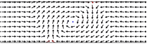
A head-to-head domain wall carries a fixed nonzero amount of magnetic charge ( in a strip of width ), with a finite density in the bulk, , or at the film edge, (or, most likely, both). Therefore van den Berg’s method is not, strictly speaking, applicable. Nonetheless, an examination of the detailed structure of a vortex wall (bottom panel of Fig. 1) McMichael and Donahue (1997) shows that it indeed contains two edge defects and a vortex in the middle. The edge defects share one of their Neel walls; the vortex resides at its middle point.
In what follows we consider a model of the vortex domain wall that is free of bulk magnetic charge. Thus all of the charge is expelled to the edges. Under this restriction it is possible to construct a vortex domain wall by piecing together the vortex and two edge defects as shown in Fig. 1. The resulting structure contains domains with uniform and curling magnetization. In a strip with the shared Neel wall and the vortex core at , the two curling domains in the regions are separated by parabolic Neel walls from domains with horizontal magnetization; they also merge seamlessly with other uniform domains along the lines and .
This trial state exaggerates the accumulation of surface magnetic charge thereby overestimating the normal component of magnetization at the edge. Nonetheless it captures the major features of a vortex domain wall.


The construction of a domain wall out of the three defects is not unique and has (at least) one degree of freedom: the vortex can be placed anywhere along the shared Neel wall . When the vortex core reaches the edge, it is absorbed by the edge defect. Their fusion creates an edge defect with the winding number (Fig. 2). As can be seen from the figure, the defect is rather extended (length ) and, in accordance with our previous remarks, contains magnetic charge (all of it at the edge in this model). This structure is topologically equivalent to the transverse domain wall in the exchange limit Tchernyshyov and Chern , where both edge defects are pointlike. The transverse walls observed in experiments Kläui et al. (2003) and simulations McMichael and Donahue (1997) are midway between these two extremes: the defect definitely has a wider core, although its extent is less than .


To determine the equilibrium configuration of the composite wall we computed the total energy of the composite wall and minimized it with respect to the vertical coordinate of the vortex. The energy is the sum of the following terms.
The magnetostatic energy coming from the Coulomb-like interaction of the magnetic charges spread along the edges with the line densities for the upper and lower edges, respectively. It includes the interaction of magnetic charges on the same edge and on different edges:
| (1a) |
The total magnetostatic energy is of the order . It represents the dominant contribution in sufficiently wide and thick strips.
The energy of the Neel walls can be computed as a line integral
| (1b) |
where is a line element of the wall. The wall surface tension depends on the angle of rotation across the wall, which stays at 90 degrees along straight segments and varies along parabolic ones. See Ref. Chern et al., for details of the calculation. This term is of the order .
The exchange energy
| (1c) |
where is the area around the vortex where magnetization curles. This term is of the order .
An investigation of the phase diagram and a quantitative comparison of this model with the numerical and experimental results is currently under way. In what follows we report some preliminary findings.
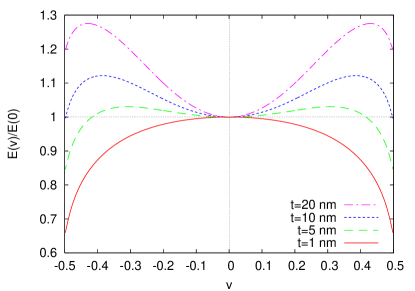
The evolution of the energy curve at a fixed width and varying thickness is shown in Fig. 4. For substantially wide and thick strips, the one and only minimum of energy is achieved with the vortex in the middle of the strip, in agreement with numerical simulations McMichael and Donahue (1997).
As the cross section decreases, a local minimum develops with the vortex core at the edge of the strip. In this configuration (Fig.2) the vortex and the edge defect have merged to form an extended edge defect. The configuration is highly reminiscent of the transverse wall McMichael and Donahue (1997) that is known to coexist with the vortex wall over a range of cross sections Kläui et al. (2003). The transverse wall becomes a global minimum of energy when the cross section becomes small enough. The vortex wall remains locally stable until it becomes a local maximum of energy.
(The reader should note that the curve for thickness nm shown in Fig. 4 is only an extrapolation: the energetics of the Neel wall in very thin films is a nonlocal problem Hubert and Schaefer (1998) to which our estimate based on Eq. (4) in the companion paper Chern et al. does not apply. Nonetheless, the overall trend reflected by the shape of the curve is correct: in the exchange limit domain walls containing 3 defects are locally unstable.)
In addition to these two wall configurations, which have been previously discussed in the literature, we have found two metastable states that corrsepond to local minima of energy . One of them has the vortex core rather close to but not exactly at the edge (top panel of Fig. 3). We have observed domain walls of this kind in numerical simulations (bottom panel of Fig. 3). The other metastable state occurs when the energy curve has two symmetric minima around . This is a vortex wall with the vortex core slightly off center. Because the off-center minima are rather shallow it may be difficult to observe such states in practice: even slight imperfections of the nanoparticle can change the potential landscape .
The simple model of a domain wall in the magnetostatic limit presented in this paper shows a qualitative agreement with observations. Its quantitative comparison with available experimental and numerical data is in progress. At a minimum, the model provides an insight into the nature of the vortex domain walls in a regime relevant to experiments. It corroborates our earlier suggestion Tchernyshyov and Chern that domain walls in nanostrips can be viewed as composite objects, which may be helpful in understanding their dynamical properties.
Acknowledgment. We thank C.-L. Chien, J.-G. Zhu, and F. Q. Zhu for discussions. This work was supported in part by the NSF Grant No. DMR05-20491.
References
- Zhu et al. (2000) J.-G. Zhu, Y. Zheng, and G. A. Prinz, J. Appl. Phys. 87, 6668 (2000).
- Zhu et al. (2004) F. Q. Zhu, D. Fan, X. Zhu, J.-G. Zhu, R. C. Cammarata, and C.-L. Chien, Adv. Mater. 16, 2155 (2004).
- Kläui et al. (2003) M. Kläui, Vaz, J. A. C. Bland, T. L. Monchesky, J. Unguris, E. Bauer, S. Cherifi, S. Heun, A. Locatelli, L. J. Heyderman, et al., Phys. Rev. B 68, 134426 (2003).
- McMichael and Donahue (1997) R. D. McMichael and M. J. Donahue, IEEE Trans. Magn. 33, 4167 (1997).
- (5) O. Tchernyshyov and G.-W. Chern, cond-mat/0506744.
- Moser (2004) R. Moser, Arch. Rational Mech. Anal. 174, 267 (2004).
- Kurzke (to appear) M. Kurzke, Calc. Var. PDE (to appear), preprint 14/2004, Max Planck Institute for Mathematics in the Sciences.
- Hubert and Schaefer (1998) A. Hubert and R. Schaefer, Magnetic domains (Springer, 1998).
- (9) G.-W. Chern, H. Youk, and O. Tchernyshyov, these Proceedings; cond-mat/0508740.
- van den Berg (1986) H. A. M. van den Berg, J. Appl. Phys. 60, 1104 (1986).
- Donahue and Porter (1999) M. J. Donahue and D. G. Porter, Interagency Report NISTIR 6376, NIST, Gaithersburg (1999), OOMMF User’s guide, Version 1.0. http://math.nist.gov/oommf.