Observation of Macroscopic Structural Fluctuations in bcc Solid 4He
Abstract
We report neutron diffraction studies of low density bcc and hcp solid 4He. In the bcc phase, we observed a continuous dynamical behaviour involving macroscopic structural changes of the solid. The dynamical behaviour takes place in a cell full of solid, and therefore represents a solid-solid transformation. The structural changes are consistent with a gradual rotation of macroscopic grains separated by low angle grain boundaries. We suggest that these changes are triggered by random momentary vibrations of the experimental system. An analysis of Laue diffraction patterns indicates that in some cases these structural changes, once initiated by a momentary impulse, seem to proceed at a constant rate over times approaching an hour. The energy associated with these macroscopic changes appears to be on the order of kT. Under similar conditions (temperature and pressure), these effects were absent in the hcp phase.
pacs:
67.80.Mg, 67.12.Ld, 61.72.MmI Introduction
It is well known that quantum solids exhibit unique properties concerning internal motion of atoms, properties which are most prominent in solid Helium at the lowest density. Examples include the rapid atomic exchange in 3Heguyer , extremely fast annealing of bcc 4Hesanders , and mass diffusion at a rate comparable to that of a liquidberent . Recently, experimental reports have appeared suggesting that at temperatures below 0.2K, superfluidity may occur in hcp phase of solid 4He goodkind ; Chan&kim1 ; Chan&kim2 . In the following, we show evidence of yet another unusual behaviour of bcc solid 4He, namely that inside a crystal, macroscopic structural changes can occur which may continue unabated for a long time. Our proposed interpretation of these observations is that the structural changes are gradual orientation changes of macroscopic crystalline grains, with the energy involved in the process being comparable to that of thermal fluctuations. A comparison of experiments which we carried out over the last several years suggests that these structural changes are triggered by sporadic momentary vibration in the laboratory, some of which couple to the cell containing the solid. In section II, we describe the experimental results. The interpretation of these results is presented in section III.
II Experimental
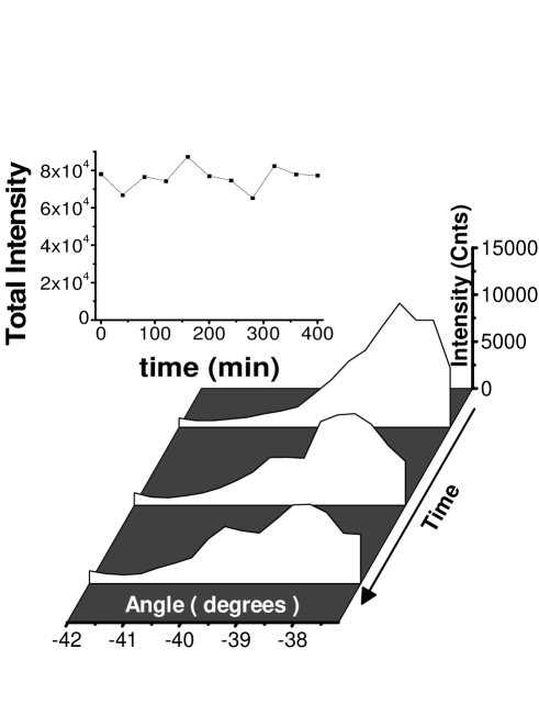
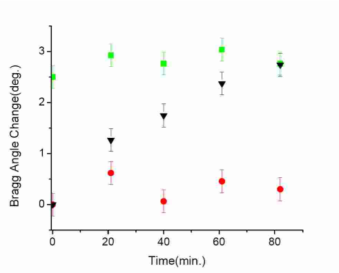
In this work, we investigated structural changes of low density He crystals using neutron diffraction. For the most part, the results discussed here refer to two separate experiments performed at the Institut Laue Langevin. We first discovered these effects during an experiment on the IN-14 triple axis spectrometer, using a beam of cold neutrons having = 4.05 and a cross sectional area of several cm2. In this experiment, we grew He crystals inside a spherical cell having a volume of 8.9 cm3. The spherical shape was chosen to maintain the same scattering intensity regardless of its orientation relative to the beam. Crystals of bcc 4He were grown at a constant temperature, typically 1.650 K. Once the cell was completely filled with solid, the temperature of the cell was further reduced by 10 mK, to ensure that all the He in the filling line also solidified and the crystal in the cell is well isolated. Subsequent experiments were done on the solid phase under conditions of constant density and temperature ( 1mK). During the crystal growth, we monitored the intensity of the (110) Bragg reflection. At this stage, the diffraction pattern consisted of a single large intensity peak, which indicated that the cell contained one large single bcc crystal. Soon after starting the procedure to orient the crystal in the beam by rotating and tilting the cryostat, we found that the crystal broke up into several large, slightly misoriented pieces. Further diffraction scans revealed a very interesting dynamic effect; the various sub-crystals changed their orientation and relative size continuously, in a seemingly random fashion. Typical elastic diffraction spectra near the (110) Bragg reflection, taken an hour apart, are shown in Figure 1. One can see that with time, spectral weight is shifted away from the main peak, indicating that parts of the crystal change their spatial orientation. The inset in Figure 1 shows the total integrated intensity of these spectra, which remains almost constant as a function of time. Hence, these spectra reflect spontaneous changes involving the whole crystal, with each sub-peak in the diffraction spectrum representing the orientation of a macroscopic grain, some cm3 in size. We emphasize that the whole process takes place in a cell which is completely filled with solid. This solid-solid transformation process persisted unabated for the duration of the experiment, close to a week.
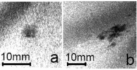
In order to learn more about this effect, we performed a second experiment, using a white beam neutron Laue Camera (S42). The white beam has neutrons with 1 and a small divergence(8’). This small divergence allows for the resolution between crystalline grains misaligned by less than 1∘. In order to learn how to interpret the Laue images, we first grew a small single crystal in a separate cell with a 0.2 cm3 volume. Figure 2(a) shows a Laue image with a Bragg spot of a bcc single crystal. One can see that the intensity within the Bragg spot is quite uniform. In our experience with observing He crystals in our optical cryostattuvy2 , cycling the crystal through the hcp-bcc transition results in a break up of the single crystal into smaller grains. After carrying out this procedure, it is seen in Figure 2(b) that the Bragg spot is no longer uniform, showing streaks. These streaks are due to Bragg reflections from crystal grains which are now slightly misoriented. The larger size of the spot reflects the larger rocking curve of the whole crystal.
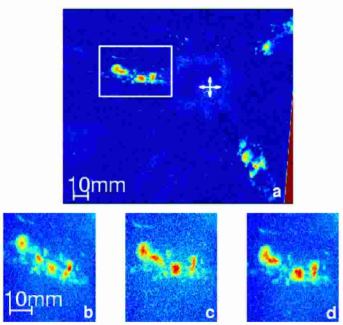
In the second part of the Laue camera experiment we grew another bcc solid, this time in the large spherical cell. The solid was grown intentionally to produce several slightly misoriented crystals. The Laue diffraction pattern is shown in Figure 3. Background scattering due to the cell walls was substracted from the image. In contrast to X-rays, neutrons penetrate through the whole sample, and images are acquired in transmission mode. With the large cell, the crystal size along the beam direction is larger than the cross section of the neutron beam. Since the neutrons penetrate the whole crystal, one expects the Laue diffraction spots to become extended along the radial direction relative to the center of the image. In this case, the size of the diffraction spot on the image, , is linear related to the actual size of the sample. More accurately, for a perfect single crystal of diameter , the size of the Bragg spot along the radial direction of the image is , where is the width of the beam and is the angle satisfying the Bragg condition. The angular width of the Bragg spots is proportional both to the rocking curve of the crystal and the width of the beam. In Fig. 3(a), three large spots can be seen, roughly 120∘ apart, with some sub-structure inside each one. By simulating the diffraction processfilhol , we identified these 3 large spots as (110) Bragg reflections, with the crystal oriented so that its [111] direction is at an angle of 18∘ to the neutron beam. Due to the Debye-Waller factor of solid He, (110) Bragg reflections are much more intense than any higher order reflection and therefore most likely to be seen. For a real crystal with a finite rocking curve, the Bragg spot will be larger than , which characterizes a perfect single crystal. However, the sum of the individual sizes of the small features inside each large Bragg spot should equal . We checked and found that this indeed is the case. According to what we learned from the images shown in Fig. 2, the sub structure inside each large spot in Fig. 3(a) indicates that the crystal is made of several slightly misoriented grains. The dynamic behavior of the crystal can then be followed by monitoring the changes of such images as a function of time. Figures 3(b), 3(c), and 3(d) show three successive images of one of the spots, taken 15 minutes apart. 15 minutes were sufficient to obtain an image with a good contrast, with typical features having an intensity of 5-10 times the noise level. It is evident that some features inside the large spot change with time, either losing intensity at the expense of others which become more intense, or changing their position from one frame to the next. Similar type changes occur simultaneously in all three large spots. Intensity variations associated with these changes are on the order of of the total intensity of the large spot. This implies that the size of the crystal grains which undergo these changes is a fraction of 1 cm3 (in contrast to the triple axis experiment, the beam cross sectional area of the Laue camera is smaller, so we see only part of the spherical cell). As in Fig. 1, these changes indicate that some crystal grains inside the cell change their orientation with time.
Structural changes of an imperfect crystal can be a natural part of an annealing process. At a given temperature, annealing continues for as long as thermal activation can induce further changes in the crystal. The temporal extent of this process was investigated by several authorssanders ; beamish ; hiki ; berent . At temperatures above 1K, which are relevant to our experiment, it was found that the typical time scale to anneal a crystal is less than one hour. In the narrow range in which the bcc phase exists, the most efficient way to anneal the crystal is to heat it up until one just reaches the melting curve. Under melting conditions, the crystal is surrounded by superfluid which can relieve stress very efficiently by transporting heat and matter. Stress relief by this method was demonstrated in several experiments in which the crystal was subjected to mechanical deformationsanders ; berent ; berent2 . In order to check whether annealing is the process seen here, we raised the temperature by 10 mK, and held the crystal on the melting curve overnight, a very long time by the the criteria described above. Both during and after the annealing, the crystal continued to show random structural changes at apparently an undiminished rate for the duration of the experiment (close to two weeks). We conclude that these macroscopic structural changes are not a part of an annealing process.
Next, we try to identify the source of the applied stress which induces the structural changes. There are two possible sources of stress, of thermal and mechanical origin. Thermally induced stress results from the relatively large thermal expansion of solid He. Since crystals are confined by rigid boundaries, any temperature change will generate stress. Thermally induced stress was observed by Hiki and Tsuruokahiki , who followed the dynamics of dislocations in He crystals using ultrasonic techniques after intentional abrupt temperature changes of 50 mK. A similar study was carried out by Beamishbeamish , who observed the relaxation of stress induced by large ultrasonic pulses upon heating the crystal by several hundred mK. In all our experiments at the ILL, both long term and short term temperature stability was within 1mK. Therefore, thermally induced stress is a priori much smaller. The temperature profile within the cryostat in both experiments discussed here (IN-14 and the Laue experiment) was identical, with the temperature gradient in the cryostat tail static to within the same precision over the duration of the experiment. Yet, the size of of the structural changes seen in these two experiments is very different. Finally, we may add that in our previous experiments, no structural changes were observed. In those experimentstuvy , the cell was better vibration isolated, while its thermal stability was the same. We can therefore conclude that thermally induced stress is inconsequential in the present context.
Let us now consider mechanically generated stress. First, there is no static applied stress in our experiment. However, a fluctuating mechanical stress does exist due to external vibrations coupled to the solid cell. The importance of this source of stress can be appreciated by comparing the structural changes observed during the three different experiments which we carried out at the ILL. In the first experimenttuvy , the cell was rigidly attached to a 1/2” diameter stainless steel tube. In this experiment, despite the fact that the cryostat was continously rotating on the spectrometer, we saw no structural changes. Next, in the Laue camera experiment, the spherical cell was clamped in a double plate structure attached to 4 thin wall 1/8” tubes, which are much less rigid than the 1/2” tube. The cryostat holding the cell was static. In this experiment, we saw structural changes amounting to orientation changes of 2∘-3∘ over the duration of the experiment. Finally, in the experiment done on the IN-14 triple axis spectrometer, the double plate support structure attaching the spherical cell to the 4 thin wall 1/8” tubes was removed in order to reduce the scattering background. The cell was therefore more susceptible to vibrations. Furthermore, during position changes, the cryostat together with the spectrometer were subject to a higher acceleration than used previouslytuvy . In this experiment, we observed cumulative orientation changes of 10∘-20∘. The importance of the acceleration was tested directly by monitoring the Bragg reflections from the crystal while changing the acceleration of the cryostat (and of the experimental cell). When the motion of the cryostat was ”soft”, meaning very low acceleration, we observed that the Bragg reflections of the crystal did not change with time, meaning that there were no structural changes. When the acceleration was increased, we immediately observed that the crystal broke up exactly in the way shown in Fig. 1. Since the acceleration is of short duration, it follows that large enough momentary mechanical acceleration leads to crystalline changes (all of this was done under isothermal conditions).The comparison of all these experiments strongly suggests that the continuous solid-solid transformation process reported here is driven by mechanical vibrations of the cell.
The cell containing the solid He is a spherical metallic shell, attached to the end of a thin long rod (1m) suspended from a top plate of the cryostat. If the cryostat is suddenly moved, it will excite pendulum-like vibrations of the cell. The pendulum frequency comes out about 0.5Hz, which is within the band of typical building vibrations discussed belowbaklakov . Another possibility is an excitation of transverse elastic oscillations of the rod which couple into the cell. We estimate the resonant frequency of the lowest mode around 100Hz. The metal cell itself is not affected by these vibrations, however the solid He, which is compressible, will be affected by the stress exerted on it by the cell wall. If the vibration is strong enough, the stress will exceed the critical shear stress and structural changes will follow.
Typical low frequency vibrations spectrum in a laboratory has a 1/fα dependence, with 2 1 baklakov . To affect the solid, the vibration amplitude of the cell must exceed the critical shear stress of the solid (3104 dyne/cm2sanders ). Because of the 1/f dependence of the vibration spectrum, vibrations having an amplitude large enough to shear the solid will be less frequent. Focusing on the Laue experiment, we now estimate the likely interval between successive vibrations which induce structural changes. If the exposure time of a Laue image is long compared with the interval between vibrations, individual diffraction spots such as the small features shown in Figs. 3(b)-(d) will be able to shift back and forth on the image under a sequence of uncorrelated vibrations which cause random changes during the exposure period. The Laue images exhibit the intensity integrated over the exposure time. If the exposure time is long enough compared with the interval between structural changes, the image should look uniform, like in Fig. 2(a). If however the exposure time is short in comparison, the images should show isolated diffraction spots. We found that after an exposure time of 10 hours, the image indeed looks quite uniform, namely many vibrations have occurred. Shorter exposure times of 15 minutes to 1 hour produce images such as Figs. 3(b)-(d), showing distinct diffraction spots, with some apparent changes from one frame to the next. From these observations, we deduce that the interval between vibrations in the Laue experiment is at least several minutes.
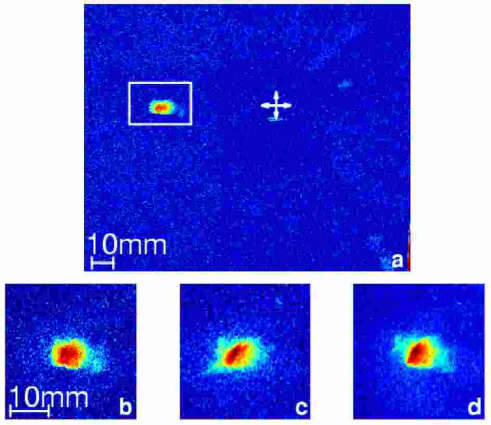
It is interesting to check whether this phenomenon occurs only in the bcc phase or also in the hcp phase. To that end, we repeated the experiment with a hcp helium solid grown at a constant temperature of 1.80 K, which is still in the regime of low density solid. In Figure 5(a) one can see a single Bragg spot,which is uniform and small compared to . The fact that only one Bragg spot was seen may indicate that the polycrystal is made up of grains which are strongly misoriented, so that only one grain satisfies the Bragg condition within the spherical angle spanned by the image plate, while the other grains do not and are therefore not visible. A similar image was obtained with another hcp crystal, grown in the smaller cell. In contrast to the bcc solid, the hcp Laue image changed much less with time (see Figure 4(b)- 4(d)). These observations are consistent with the work of Iwasa et al.iwasa2 , who studied hcp 4He crystals using high resolution X-ray topography. Similarly to our observations, these authors have not reported any dynamic behaviour of the hcp solid.
III Discussion
In this section, we outline one example of a classical mechanism which is consistent with the structural changes observed in the experiment. Analysis of the diffraction patterns from the Laue camera experiment indicates that the bcc crystal is made of grains separated by low angle (3∘-7∘) grain boundaries. The shift of the diffraction spots with time as shown in Fig. 3(b)- 3(d); indicates that the orientation of some grains changes. Orientation changes could result either through straightforward rotation of grains or from a gradual translation of grain boundariescomment . Brute force rotation of an arbitrarily shaped solid grain within a solid matrix involves massive displacements of atoms at the boundaries through vacancy diffusionberent2 ; dyumin and dislocation climb. It requires a very specially arranged stress field. In the absence of such field, vacancies and dislocations will not flow in a correlated way which is needed for a macroscopic rotation of a grain. Consequently, rotation of grains is less likely than the mechanism discussed below.
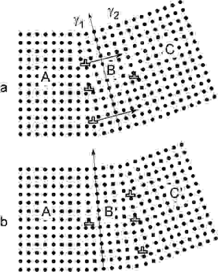
A mechanism which appears more plausible involves a gradual translation of a low angle grain boundary inside the crystal, and can in principle proceed via dislocation glide in a slip plane. The Laue images are consistent with the solid being made up of grains separated by simple tilt grain boundaries. These consist of parallel edge dislocations of the same sign, spaced by , with the Burgers vector and the misorientation angle. Figure 5 illustrates one possibility how glide of individual dislocations can gradually change the orientation of a grain. In the figure, dislocations move from grain boundary to grain boundary at some rate. As a result, the misorientation angle of decreases and that of increases. Consequently, section B of the crystal, bounded between grain boundary and , changes its orientation continuously starting from that close to grain C and ending with that of grain A. In order for this process to occur, dislocations must be able to detach themselves from the grain boundary . A perfect tilt grain boundary is stabilized mainly through the elastic force between edge dislocations resulting from their mutual stress field. It is however possible for the dislocation to wander away from the grain boundary through nucleation of kink pairs overcoming the Peierls barrier, which advance the dislocation an atomic distance at a time in the slip plane. To examine this possibility, we evaluate the probability of formation of kink pairs. A classical expression estimating , the formation energy of a pair of kinksSeeger ; hiki is
| (1) |
Here is the energy of a kink, is the height of the Peierls potential barrier, with the self energy per unit length of a dislocation, is the shear modulus and the Peierls stress. The critical distance separating the two kinks so that they do not annihilate, , is given by . For bcc solid 4He, the shear modulus = 2.4108 dynes/cm2greywall , the lattice parameter 4.11, and the Peierls stress is 10-4 - 10, depending on the particular type of dislocationhiki ; iwasa . For edge dislocations in bcc solid 4He, the Burgers vector is . Taking an average value of 10 ,we find =0.29K. Quantum correctionsiwasa , namely zero point motion, enhance the exchange probability of atoms and decrease further. At the temperature of our experiment, T=1.65K, there should be a sizable population of thermally excited kink pairs and dislocation glide should be possible. This conclusion is supported by experimental findings; at temperatures similar to ours, Sanders et al.sanders could not detect any increase in ultrasonic attenuation in bcc crystals under dynamic deformation. This implies that dislocations generated by a moving piston were able to reach the walls and annihilate at the same rate they were created. Similar conclusion regarding the large mobility of edge dislocations was arrived at by Hiki and Tsuruokahiki .Torsional oscillator studies by Miura et al.miura show that in pure crystals below 1K, pinning of dislocations occurs at the intersection with other dislocations which are immobile. In an impurity free crystal above 1K, where all the dislocations are highly mobile, there are practically no pinning sites and dislocation should be able to wander from one grain boundary to another.
Crystalline orientation changes consistent with the mechanism shown in Figure 4 and discussed in the preceding paragraph were actually observed in our experiment. In some cases, we were able to resolve a steady progress of a diffraction spot on the image plate from one frame to the next over several consecutive frames. We show these data in Fig. 6. The moving diffraction spot splits off from a static spot, and terminates in another static spot. The intensity of the moving spot indicates that the size of the crystal grain associated with it is about 0.07 cm3. The total time span over which this steady progress was observed was over one hour. It seems that in this particular case, the interval between some momentary vibrations was long enough so that we could observe the whole relaxation process. Referring to Figure 4, the rate at which dislocations cross from one grain boundary to the other, , is given by , with the size of the grain boundary. For the data shown in Fig. 6, we calculate 10 dislocations/sec. This is a very small number compared with a typical dislocation density in He crystals of 104-105 cm-2iwasa2 . Given that the energy involved in the motion is that of the kinks, =0.29K, the implication of our observation is that macroscopic structural changes can take place with an energy input of order kT. Hence, the term ”macroscopic structural fluctuations” seems appropriate to describe the behaviour of bcc crystals. In closing this paragraph, we stress that the mechanism illustrated above is proposed on grounds of plausibility and is not a full theoretical model, so that other interpretations of these unusual effects are possible.
Finally, we address the different behaviour of the bcc and hcp crystals. This difference can perhaps be understood in the following way: In the bcc structure, the edge dislocation with the lowest energy has a Burgers vector [111]. The slip planes for this type of dislocation are {110}, {112}, and {123}, offering 12 different slip planes for any particular [111] dislocation. Hence, easy motion of low angle grain boundaries can take place easily in practically any direction. In contrast, in the hcp structure there is only one preferred slip plane, {0001}, which implies that motion of grain boundaries in hcp will be strongly restricted relative to the bcc phase.
IV Acknowledments
We are grateful to Frederic Thomas, Shmuel Hoida, M. Blein, and P. Thomas for their invaluable help, and N. Gov for discussions. This work was supported in part by the Israel Science Foundation and the Technion VP Research fund.
References
- (1) R. A. Guyer, R. C. Richardson, and L. I. Zane, Rev. Mod. Phys. 43, 532 (1971).
- (2) D. J. Sanders, H. Kwun, A. Hikata and C. Elbaum, Jour. Low Temp. Phys. 35, 221 (1979), Phys. Rev. Lett. 40, 458 (1978).
- (3) I. Berent and E. Polturak , Phys. Rev. Lett. 81, 846 (1998).
- (4) J. M. Goodkind,Phys. Rev. Lett. 89, 095301(2002).
- (5) E. Kim and M.H.W Chan, Nature 427, 225(2004).
- (6) E. Kim and M.H.W. Chan, Science 305,1941 (2004).
- (7) T. Markovich and E. Polturak, Jour. Low Temp. Phys. 123, 53 ( 2001).
- (8) Simulations were done using ”Orient Express”, a computer program written by A. Filhol.
- (9) J. R. Beamish and J. P. Franck, Phys. Rev. B28, 1419(1983).
- (10) Y. Hiki and F. Tsuruoka, Phys. Rev. B89, 696(1983).
- (11) I. Berent and E. Polturak, Jour. Low. Temp. Phys. 112, 337(1998).
- (12) T. Markovich, E. Polturak, J.Bossy and E. Farhi, Phys. Rev. Lett. 88, 195301 (2002).
- (13) B. Baklakov, T. Bolshakov, A. Chupyra, A. Erokhin, P. Lebedev, V. Parkhomchuk, Sh. Singatulin, J. Lach and V. Shiltsev Phys. Rev. Special Topics - Accelerators and Beams 1,031001(1998).
- (14) I. Iwasa, H. Suzuki, T. Suzuki, T. Nakajima, I. Yonenaga, H. Suzuki, H. Koizumi, Y. Nishio, and J. Ota, Jour. Low. Temp. Phys. 100, 147(1995).
- (15) For completeness, there is a possibility for the long time dynamics being due to the solid behaving as a glass. However, some key characteristics of glass-like behavior are missing in our observations. First, the diffraction pattern is characteristic of a single crystal or an aggregate of a few crystals, each one of a very high quality. The diffraction pattern does not show any amorphous characteristics of glass like materials. Second, thermally activated relaxation in glasses leads to a gradual transition from an amorphous to crystalline state. This relaxation proceeds only in one direction, and simply stops if the temperature is reduced. Application of mechanical stress leads to amorphization, and again, the process goes only in one direction. Neither of these relaxation types fits our observations, in which we see crystal transform back and forth around the same state.
- (16) N. V. Dyumin, N. V. Zuev, S. V. Svatko, and V. N. Grigoriev, Sov. Jour. of Low Temp. Phys. 17, 458 (1991).
- (17) I. Iwasa, N. Saito, and H. Suzuki, Jour. Phys. Soc. Jap. 52, 952(1983).
- (18) A. Seeger, Phil. Mag. 1, 651 (1956).
- (19) D. S. Greywall,Phys. Rev. B13, 1056(1976).
- (20) Y. Miura, K. Ogawa, K. Mori, and T. Mamiya, Jour. Low. Temp. Phys. 121, 689(2000).