Quantitative description of the azimuthal dependence of the exchange bias effect
Abstract
While the principal features of the exchange bias between a ferromagnet and an antiferromagnet are believed to be understood, a quantitative description is still lacking. We show that interface spin disorder is the main reason for the discrepancy of model calculations versus experimental results. Taking into account spin disorder at the interface between the ferromagnet and the antiferromagnet by modifying the well known Meiklejohn and Bean model, an almost perfect agreement can be reached. As an example this is demonstrated for the CoFe/IrMn exchange biased bilayer by analyzing the azimuthal dependence of magnetic hysteresis loops from MOKE measurements. Both, exchange bias and coercive fields for the complete 360∘ angular range are reproduced by our model.
pacs:
75.60.Jk, 75.70.-i, 75.70.CnThe exchange bias system refers to the shift of the ferromagnetic (F) hysteresis loop to positive or negative values when the F system is in contact with an antiferromagnetic (AF) system and cooled in an applied magnetic field through the Néel temperature of the AF system. The exchange bias (EB) phenomenon is associated with the interfacial exchange coupling between ferromagnetic and antiferromagnetic spin structures, resulting in a unidirectional magnetic anisotropy bean:1956 . While the unidirectional anisotropy was successfully introduced by Meiklejohn and Bean (M&B), the origin of the enhanced coercive field is yet not well understood. The details of the EB effect depend crucially on the AF/F combination chosen and on the structure and thickness of the films berkowitz:1999 ; nogues:1999 . However, some characteristic features apply to most systems: (1) and increase as the system is cooled in an applied magnetic field below the blocking temperature of the AF layer, where is the Néel temperature of the AF layer; (2) the magnetization reversal can be different for the ascending and descending part of the hysteresis loop fitzsimmons:2000 ; radu:2002:1 ; gierlings:2002 ; lee:2002 ; radu:2003:1 ; (3) thermal relaxation effects of and indicate that a stable magnetic state is reached only at very low temperatures geoghegan:1998 ; goodman:2000 ; radu:2002:2 .
Several theoretical models have been developed for describing possible mechanisms of the EB effect, including domain formation in the AF layer with domain walls perpendicular to the AF/F interface malozemoff:1987 , creation of uncompensated excess AF spins at the interface schulthess:1998 , or the formation of domain walls in the AF layer parallel to the interface mauri:1987 ; kim:2005 . Another approach is the consideration of diluted antiferromagnets in an exchange field. In the work described in Ref. milt:2000 ; keller:2002 ; nowak:2002 the discussion about compensated versus uncompensated interfacial spins is replaced by a discussion of net magnetic moments within the antiferromagnetic layer. Depending on the complexity of the system, the models can explain some but not all features of experimental hysteresis loops. Here we provide a new model which can describe all features, including the azimuthal dependence of , , and the AF thickness dependence. In this letter we concentrate on the azimuthal dependence (AD), the thickness dependence will be reported elsewhere.
The AD of and is an important feature of all EB systems. First experiments were performed on NiFe/CoO bilayers ambrose:1997 , where it was suggested that it can be best described by a cosine series expansions with odd and even terms for and , respectively. A recent study of IrMn/CoFe bilayersouton:2005 showed that even so good agreement between the data and the simulations based on the cosine functions can be achieved, still some disagreement exists. In an another approach, Mewes et al. mewes:2002 showed that the AD of and can be well described within the Stoner-Wohlfarth model. However the magnitude of the coercivity is not explained.
We have measured the AD of CoFe/IrMn exchange bias bilayers via longitudinal (L) and transverse (T) magnetization curves. The experimental data are described by a modified M&B model assuming the existence of a spin disorder (SD) at the F/AF interface. In the F/SD/AF system the SD layer has the role to reduce the EB-field and to mediate coercivity from the AF to the F layer. The formation and existence of the SD layer has been shown in Ref. radu:2003:1 ; Radu:xrms ; roy:2005 ; gruyters:2005 . We believe that it is an essential feature of all EB systems.
Exchange-biased F/AF polycrystalline schmalhorst:2003 ; hoink:2005 bilayers were prepared by magnetron sputtering on substrates, covered by a protection layer. The base pressure was below Torr at an Ar pressure of Torr. The initial EB direction is set by an annealing step after deposition for 1 h at 548 K which is higher then the blocking temperaturenogues:1999 of exchange bias systems having IrMn layer as the AF layer. The annealing magnetic field kOe was applied and maintained parallel to the film plane hoink:2005 .
The sample was measured using a vector-MOKE setup westphalen:2005 . A number of 360 pairs of L- and T- components of the magnetization ( and respectively) were measured for an external field orientation with respect to the field cooling direction ranging from to . All loops were taken at room temperature. In this geometry, the sample is kept fixed during the measurements, whereas the orientation of the applied external field was varied. Characteristic L- and T-magnetization curves are shown in Fig. 1. In order to observe fine variations of the EB field, the one degree increment of the azimuthal angle is required. The L-hysteresis loops were used to extract the coercive fields and as shown in Fig. 2a, which further provides the coercive field and the EB field as plotted in Fig. 2c.
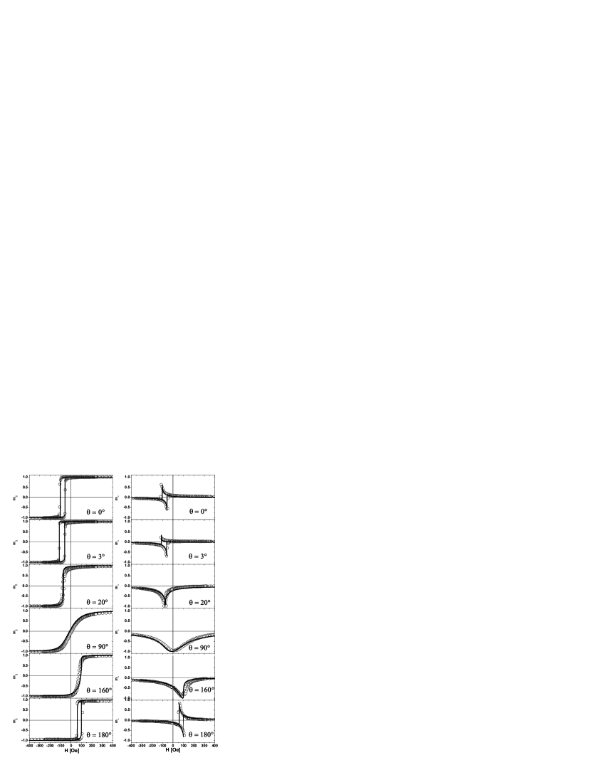
We first discuss the experimental observations in Figs. 1, 2a, and 2c. In Fig. 1 some representative L- and T-loops are shown. A distinct feature of the system is the magnetization reversal which occurs via coherent rotation paul:2004 as seen from the non-vanishing transverse loops, which are remarkably well reproduced by numerical simulations(solid lines), to be discussed further below. The maximum EB field is achieved at (see Fig. 2c and 2d), where is the azimuthal angle with respect to the field cooling direction defined as . This off-angle is one of the salient features reported here, as usually the maximum of the EB field is believed to occur parallel to the field cooling direction.
The L-loop at is completely symmetric. This is also seen in the transverse magnetization, where the forward and reverse components have the same magnitude, but are doubly mirrored with respect to and . This is not always the case. Only a few degrees forward at both, L and T-loops become asymmetric. The forward branch of the L-loop is steep, while the reverse branch is more rounded. It is remarkable that within an azimuthal angle of only such a strong asymmetry of the L-loop develops. This asymmetry is different from the one observed due to the training effect radu:2002:1 ; radu:2003:1 . The former is completely reversible while the latter is not.
As the azimuthal angle is further increased, disappears at about and reappears again in a symmetrical fashion close to . The vanishing can be understood from the T-loops, where it is clearly seen that the rotation of the ferromagnetic spins do not make a complete rotation, but almost reversibly rotate within the half circle of . Therefore the angle of the magnetization orientation, from which the coercive fields are extracted, takes the same value for both and .
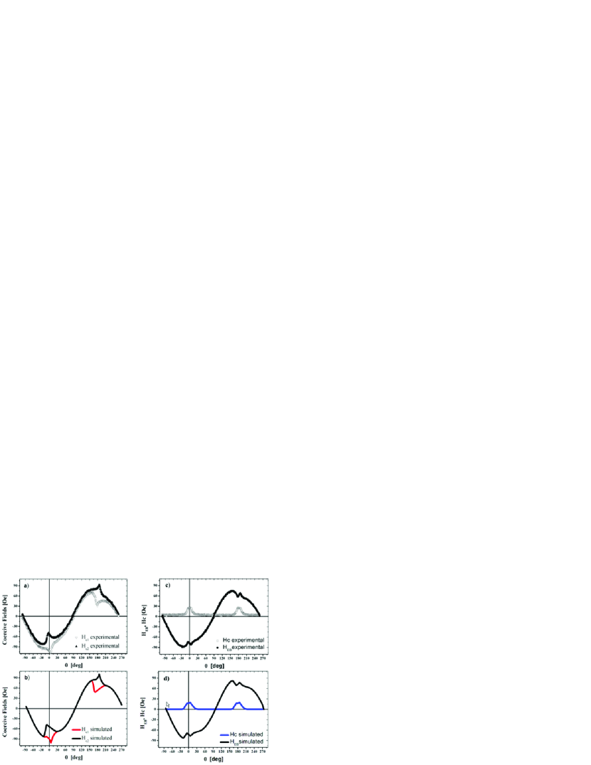
In Fig. 2a the coercive fields are plotted versus the azimuthal angle . We notice that, globally, they follow the expected unidirectional behavior bean:1956 , but some striking deviations are recognizable. In particular, close to the field cooling direction spike like features appear. While the coercive fields are well behaved for most of the angles, this is not the case for field directions close to the field cooling orientation. Here and deviate one from each other, resulting in a non-vanishing coercive field as seen in Fig. 2c. Its maximum value ( Oe) is about four times lower than the maximum value of the exchange bias field. Finite values are observed within a degree range centered at and and almost vanish outside this range.
The dependence on the azimuthal angle (solid symbols in Fig. 2c) clearly shows the unidirectional anisotropy. In addition a peculiar and sharp modulation is seen with a low amplitude. These features appear close to the field cooling orientation and also close to the opposite orientation. They cannot be reproduced satisfactorily with the empirical description based on a cosine series expansion as suggested in Ref. ambrose:1997 . Therefore we need a more realistic model, which is discussed next.
The M&B model bean:1956 assumes that the AF spins rigidly form an AF state, but they may slightly rotate as a whole during the magnetization reversal of the F layer. Within the M&B model, enhanced coercivity is not accounted for. The interface is assumed to be perfectly uncompensated with the interface AF spins having the same anisotropy as the bulk spins. However, the interface is never perfect. Roughness, deviations from stoichiometry, interdiffusion, structural defects, low spin coordination at surface sites kodama:1997 , etc. cause non-ideal magnetic interfaces. It is therefore natural to assume that, on average, a fraction of the AF spins have lower anisotropy as compared to the bulk ones. These interfacial AF spins can rotate together with the ferromagnet ohldag:2003 ; Radu:xrms ; roy:2005 . They mediate the exchange coupling, induce an enhanced coercivity, but soften the extreme coupling condition assumed by M&B. Therefore, we assume that the anisotropy of the AF interface layer varies from next to the F layer to next to the AF layer, where is the anisotropy constant of a presumably uniaxial antiferromagnet. This anisotropy gradient across the interface governs the enhanced anisotropy of the ferromagnetic layer, which otherwise would be close to zero for CoFe. So far it was believed that the enhanced coercivity in F/AF exchange biased systems is caused by compensated AF spins at the F/AF interface. We argue that for most of the AF materials a compensated or uncompensated spin having the same anisotropy as the bulk AF layer would be practically impossible to reverse by rotating the F layer. Therefore we need to assume low anisotropy AF spins in order to quantitatively describe the experimental data.
A direct indication of the rotating AF spins is revealed by soft X-ray magnetic dichroism ohldag:2003 ; Radu:xrms ; roy:2005 . Element specific hysteresis loops show that some spins belonging to the AF layer rotate reversibly with the F spins. Due to the shift of the hysteresis loop it is obvious that another part of the AF layer is frozen. Therefore the AF layer can be considered, to a first approximation, as consisting of two types of AF states. One part having a large anisotropy preserving the AF state, and another interfacial part with a weaker anisotropy, allowing the spins to rotate together with the F spins. Moreover, polarized neutron scattering radu:2002:1 ; radu:2003:1 revealed two further effects related to the magnetic state of the CoO/Co interface (which is similar to the CoFe/IrMn system mccord:2003 ) during the magnetization reversal: a) the interface is disordered containing domains and domain walls even in saturation, similar to a spin-glass system; b) the interfacial ferromagnetic spins are not collinear with the applied field direction during the reversal.
The experimental results mentioned above are in our model accounted for by two averaging interface properties: (a) the existence of low AF anisotropy spins, to which we assign an effective average anisotropy ; (b) a non-collinearity angle . Adding these two parameters, the modified M&B model reads:
| (1) | |||||
where is the reduced interfacial exchange energy, the () angle is the averaged angle of the effective SD anisotropy which can be considered as (partially) fanning in orientation with respect to the average anisotropy orientation of the AF layer macedo:2004 , is the average angle of the AF uniaxial anisotropy bean:1956 , is the magnetization of the SD interface, and is the SD interface thickness. For simplifying the numerical analysis we neglect the term, because is small. Furthermore we neglect the crystal anisotropy of the ferromagnetic layer (), which is well justified because Co70Fe30 is a soft magnetic material with a coercivity in the range of few Oersteds muhge:1995 .
The interface anisotropy, which leads to enhanced coercivity, characterizes the quality of the interface. When is zero, the system behaves ideally as described by the M&B model bean:1956 , i.e. the coercive field is zero and the exchange bias field is finite. In the other case when the interface is disordered, we relate the effective SD anisotropy to the available interfacial coupling energy as follows:
| (2) |
where is the total exchange energy of an ideal system without additional coercivity. With this assumption the absolute value of the EB field is reduced by the factor as compared to the M&B model. The factor describes the conversion of interfacial energy into coercivity through rotation of interfacial AF spins.
Next, we write the system of equations resulting from the minimization of the Eq. 1 with respect to the and angles:
| (3) | |||||
where, is the reduced field, and is the R-ratio defining the strength of the AF layer. This system of equations can easily be solved numerically, but it cannot deliver a simple analytical expression for the exchange bias. Numerical evaluation provides the angles and as a function of the applied magnetic field . The reduced L- and T- components of the magnetization are and , respectively. These are the two observables measured by vector-MOKE. Note that the anisotropic magnetoresistance (AMR) and PNR hide the chirality of the ferromagnetic spin rotation as they provide information, whereas MOKE reveals the chirality through information.
In Fig. 1 calculated magnetization components are plotted together with the experimental data points, and in Figs. 2b and 2d the azimuthal dependence of the coercive fields and exchange bias field are plotted and compared to the experimental data in Fig. 2a and 2c. In all cases we find an astounding agreement between calculated curves and experimental data. It is remarkable, that the AD of the EB field and the coercive fields ( are completely reproduced by the SD model. The parameters used are: , and . For calculating the value of the R-ratio we used the anisotropy constant () measured in Ref. steenbeck:2004 . The conversion factor is related to the magnitude of the coercive field with respect to the shift of the loop. The angle plays an important role. It represents the mean angle of the spin disorder at the interface with respect to . For instance, when is zero, the coercive field is much enhanced at as compared to the experimental data, and the azimuthal dependence of and cannot be reproduced.
Our SD model also describes the AF thickness dependence of the EB. Notably the peak like behavior close to the critical AF thickness is reproduced by Eq. 3 radu:phd , as has been recently observed for IrMn/Co heterostructures ali:2003 . The key parameters for achieving the enhanced exchange biased are the conversion factor and the -ratio. When the -ratio is close to critical value of one, the AF spins rotates to higher angles () during the magnetization reversal. Due to the intrinsic asymmetric reversal, the AF layer absorbs also asymmetrically some fraction of the coercive fields and and give rise to an increased EB field. A reduced -ratio can be achieved by either reducing the thickness of the AF layer or by reducing its anisotropy. A condition for the peak in exchange bias to occur close to the critical values of the -ratio is the conversion factor to be smaller then approx. f=0.85. A reduced factor can be achieved also at elevated temperatures through the thermal fluctuations affecting disordered interface.
In conclusion, taking into account spin disorder at the interface between the AF and F layer we have achieved a compelling agreement between the azimuthal dependence of the coercivity and exchange bias field in the IrMn/FeCo systems. The new key physical concept is a realistic state of the interface characterized by a reduced AF anisotropy. This disorder governs the enhanced coercivity in the ferromagnetic layer and reduces the exchange bias field to realistic values. We believe that this is a general feature of EB systems. By controlling the degree of spin disorder and the thickness of the interfacial layer, better control over the exchange bias of magnetic heterostructures could be achieved.
We would like to thank J. Schmalhorst, V. Höink, and H. Brückl from the University of Bielefeld for providing the samples. We gratefully acknowledge support through the Sonderforschungsbereiche 491 ”Magnetische Heteroschichten: Struktur und elektronischer Transport” of the Deutsche Forschungsgemeinschaft.
References
- (1) W. H. Meiklejohn and C. P. Bean, Phys. Rev. 102, 1413 (1956); Phys. Rev. 105, 904 (1957).
- (2) A. E. Berkowitz and K. Takano, J. Magn. Magn. Mater., 200, 552-570 (1999).
- (3) J. Nogues and I. K. Schuller, J. Magn. Magn. Mater., 192, 203-232 (1999).
- (4) F. Radu, M. Etzkorn, T. Schmitte, R. Siebrecht, A. Schreyer, K. Westerholt, and H. Zabel, J. Magn. Magn. Mater., 240, 251 (2002).
- (5) M. Gierlings, M. J. Prandolini, H. Fritzsche, M. Gruyters, and D. Riegel, Phys. Rev. B 65, 092407 (2002).
- (6) W.-T. Lee, S. G. E. te Velthuis, G. P. Felcher, F. Klose, T. Gredig, and E. D. Dahlberg, Phys. Rev. B 65, 224417 (2002).
- (7) F. Radu, M. Etzkorn, R. Siebrecht, T. Schmitte, K. Westerholt, and H. Zabel, Phys. Rev. B 67, 134409 (2003)
- (8) M. R. Fitzsimmons, P. Yashar, C. Leighton, Ivan K. Schuller, J. Nogues, C. F. Majkrzak, and J. A. Dura, Phys. Rev. Lett. 84, 3986 (2000).
- (9) D. S. Geoghegan, P. G. McCormick, R. Street, J. Magn. Magn. Mater. 177, 937 (1998).
- (10) A. M. Goodman, H. Laidler, K. O’Grady, N. W. Owen, A. K. Petford-Long, J. Appl. Phys, 87, 6409 (2000).
- (11) F. Radu, M. Etzkorn, V. Leiner, T. Schmitte, A. Schreyer, K. Westerholt, H. Zabel, Appl. Phys. A 74(Suppl1), S1570 (2002).
- (12) A. P. Malozemoff, Phys. Rev. B 35, 3679 (1987).
- (13) T. C. Schulthess and W. H. Butler, Phys. Rev. Lett. 81, 4516 (1998).
- (14) D. Mauri, H. C. Siegmann, P. S. Bagus, and E. Kay, J. Appl. Phys., 62, 3047 (1987).
- (15) Joo-Von Kim and R. L. Stamps, Phys. Rev. B 71, 094405 (2005).
- (16) P. Miltnyi, M. Gierlings, J. Keller, B. Beschoten, G. Güntherodt, U. Nowak, K. D. Usadel, Phys. Rev. Lett. 84, 4224 (2000).
- (17) J. Keller, P. Miltnyi, B. Beschoten, G. Güntherodt, U. Nowak, and K. D. Usadel, Phys. Rev. B 66, 014431 (2002).
- (18) U. Nowak, K. D. Usadel, J. Keller, P. Miltényi, B. Beschoten, and G. Güntherodt, Phys. Rev. B 66, 014430 (2002).
- (19) T. Ambrose, R. L. Sommer, and C. L. Chien, Phys. Rev. B. 56, 83 (1997).
- (20) L. E. Fernandez-Outon and K. O’Grady, J. Magn. Magn. Mater. 290-291, 536 (2005).
- (21) T. Mewes, H. Nembach, M. Rickart, S. O. Demokritov, J. Fassbender, and B. Hillebrands, Phys. Rev. B. 65, 224423 (2002).
- (22) F. Radu, A. Nefedov, J. Grabis, G. Nowak, A. Bergmann, and H. Zabel, J. Magn. Magn. Mater. doi:10.1016/j.jmmm.2005.10.064 (2005); cond-mat/0505482.
- (23) S. Roy et al., Phys. Rev. Lett. 95, 047201 (2005).
- (24) M. Gruyters, Phys. Rev. Lett. 95, 077204 (2005).
- (25) J. Schmalhorst et al., Appl. Phys. 94 5556 (2003).
- (26) V. Höink, M. D. Sacher, J. Schmalhorst, G. Reiss, D. Engel, D. Junk, and A. Ehresmann, Appl. Phys. Lett. 86, 152102 (2005).
- (27) A. Westphalen, K. Theis-Bröhl, H. Zabel, K. Rott, and H. Brückl, J. Magn. Magn. Mater., doi:10.1016/j.jmmm.2005.09.005 (2005).
- (28) A. Paul, E. Kentzinger, U. Rücker, D. E. Bürgler, and P. Grünberg, Phys. Rev. B 70, 224410 (2004).
- (29) R. H. Kodama, Salah A. Makhlouf, and A. E. Berkowitz, Phys. Rev. Lett. 79, 1393 (1997).
- (30) H. Ohldag, A. Scholl, F. Nolting, E. Arenholz, S. Maat, A. T. Young, M. Carey, and J. Stöhr, Phys. Rev. Lett. 91, 017203 (2003).
- (31) J. McCord, R. Schäfer, R. Mattheis, and K. U. Barholz, J. Appl. Phys. 93, 5491 (2003).
- (32) W. A. A. Macedo, B. Sahoo, V. Kuncser, J. Eisenmenger, I. Felner, J. Nogu s, Kai Liu, W. Keune, and Ivan K. Schuller, Phys. Rev. B 70, 224414 (2004).
- (33) Th. Mühge, Th. Zeidler, Q. Wang, Ch. Morawe, N. Metoki , and H. Zabel, J. of Appl. Phys. 77, 1055-1060 (1995).
- (34) K. Steenbeck, R. Mattheis and M. Diegel, J. Magn. Magn. Mater. 279, 317 (2005).
- (35) F. Radu, PhD Thesis, Ruhr Universität Bochum, 2005 (http://www-brs.ub.ruhr-uni-bochum.de/netahtml/HSS/Diss/RaduFlorin/diss.pdf).
- (36) M. Ali, C. H. Marrows, M. Al-Jawad, B. J. Hickey, A. Misra, U. Nowak, and K. D. Usadel, Phys. Rev. B 68, 214420 (2003).