April 5, 2005
Spin Polarization at Semiconductor Point Contacts in
Absence of Magnetic Field
Abstract
Semiconductor point contacts can be a useful tool for producing spin-polarized currents in the presence of spin-orbit (SO) interaction. Neither magnetic fields nor magnetic materials are required. By numerical studies, we show that (i) the conductance is quantized in units of unless the SO interaction is too strong, (ii) the current is spin-polarized in the transverse direction, and (iii) a spin polarization of more than 50% can be realized with experimentally accessible values of the SO interaction strength. The spin-polarization ratio is determined by the adiabaticity of the transition between subbands of different spins during the transport through the point contacts.
Generating spin-polarized currents in semiconductors is an important issue for the development of spin-based electronics, “spintronics.”[1] To manipulate electron spins, the Rashba spin-orbit (SO) interaction is useful since its strength is locally controllable by applying an electric field.[2, 3] Several spin-filtering devices for producing the spin currents have been proposed utilizing the SO interaction, e.g., three-terminal devices related to the spin Hall effect,[4, 5] a triple-barrier tunnel diode,[6] a one-dimensional system with a magnetic field,[7] and a three-terminal device for the Stern-Gerlach experiment using a nonuniform SO interaction.[8]
In the present paper, we theoretically study the ballistic transport through a semiconductor point contact (quantum wire with a narrow constriction) in the presence of Rashba SO interaction. In its absence, it is well known that the conductance is quantized in units of when the constriction changes gradually in space.[9, 10] By numerical studies, we show that the conductance is quantized even with the SO interaction and that the current is spin-polarized in the transverse direction, in the absence of magnetic field. We demonstrate that the polarization ratio can be more than 50% in InGaAs heterostructures. The spin current is obtained generally, ., in GaAs heterostructures, if the condition later described by eq. (9) is fulfilled with not only Rashba but also Dresselhaus SO interaction.[11] As spin filters, two-terminal devices with point contacts are easy to fabricate on semiconductors, compared with other devices that have been proposed.[4, 5, 6, 7, 8]
We consider a two-dimensional electron gas confined in the direction. The electric field in the direction results in the Rashba SO interaction,
| (1) |
where and are Pauli matrices. (The Dresselhaus SO interaction is discussed later.) We use a dimensionless parameter, , where
| (2) |
with being the effective mass and is the Fermi wavenumber.[12] In InGaAs heterostructures, eVm and meV [].[13, 14] Electron-electron interaction and impurity scattering are neglected. Electrons propagate in a quantum wire along the direction, with width in the direction. A hard-wall confinement potential is assumed, for and otherwise. For a narrow constriction around , we consider an extra potential at , which is analogous to that adopted in ref. 15:
| (3) |
with
| (4) |
where () and (). is a step function [ for , for ]. For fixed , is flat at and grows with increasing at or . On a line of , the potential height is given by , being maximal at . In the present paper, we fix and , where is the Fermi wavelength ().
Numerical calculations are performed using a tight-binding model on a square lattice (, ), following refs. 15 and 16.[17] The transmission coefficients are evaluated for incident electrons from the left side of the constriction () to the right (), using the Green function’s recursion method.[15] They yield the conductance through the Landauer formula.

Figure 1 shows the calculated results when . In Fig. 1(a), we plot as a function of , potential height at . The conductance quantization is clearly observed when (solid line) as well as in the absence of SO interaction (broken line). The conductance quantization is broken for (not shown here), which is addressed later. We divide the output current into two components, one carried by spin-up electrons in the direction () and the other by spin-down electrons (). Figure 1(b) presents each conductance, , as a function of . where the total conductance is at the first plateau (). The spin polarization in the direction, , increases with an increase in . Note that incident electrons are unpolarized in eight conduction channels per spin direction. These results indicate that (i) the point contact works as a spin filter, (ii) the polarization ratio is about 30% with experimental values of in this case, and (iii) the conductance is still quantized.
These calculated results can be understood as follows. We divide the Hamiltonian into two parts: ,
| (5) | |||||
| (6) |
We treat as a perturbation. When is independent of , the eigenstates and eigenvalues of are given by
| (7) | |||||
| (8) |
respectively, where are eigenstates of with eigenvalues (). are eigenstates of , representing spin-up or -down states. The dispersion relations of (subbands) are schematically shown in Figs. 2(a) and 2(b). The Fermi level is denoted by horizontal line in the quantum wire outside of the constriction, where . (The number of channels is three per spin direction in the figures, which is smaller than that in our numerical studies.) There are two situations regarding the crossings between and (). When , all the crossings take place above [Fig. 2(a)]. When
| (9) |
some of them appear below [Fig. 2(b)].[18]
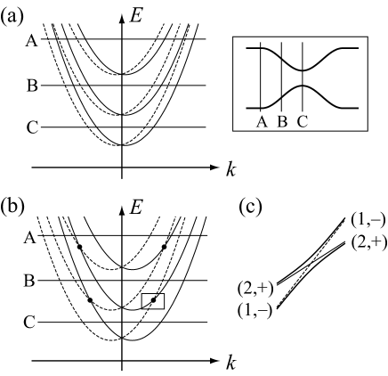
Now we consider the transport of electrons through a constriction when the conductance shows the first plateau. Except in the vicinities of the above-mentioned crossings, we assume an adiabatic transport in which the wavefunction changes gradually remaining the quantum numbers of transverse motion and of spin .[9, 10] The wavenumber changes with , which is determined by an intersection between the subband and ; positive ’s for incident electrons. Let us begin with the case of Fig. 2(a). As electrons propagate from the wire to a narrow constriction (), the subbands shift upwards. Alternatively, we move downwards in Fig. 2(a). Similarly, at , we move upwards. [Separations between the subbands increase (decrease) with at (), which is not shown in the figure.] Before the injection into the constriction (position A), there are six conduction modes, , and . At position B, modes and are conducting, whereas modes have been completely reflected. At the narrowest region (position C), only modes exist. At , the modes propagate with the transmission probability of unity, which results in the conductance quantization, . The small perturbation of does not play an important role. No spin polarization is observed in this case.
In the case of Fig. 2(b), the situation is different. Electrons pass by the crossings twice, once at and once at . Let us look at the crossing between modes and . These subbands are mixed by the perturbation , as shown in Fig. 2(c). Hence these modes change to each other with a transition probability when electrons pass through the crossing. Around the first pass (), both modes are occupied by electrons just before the modes cross. Then spin-up electrons are flipped to spin-down with probability , while spin-down electrons are flipped to spin-up with the same probability. Accordingly, no spin polarization takes place. Around the second pass (), on the other hand, mode is empty while mode is full of electrons just before the modes cross. Then spin-down electrons in the latter mode are spin-flipped to spin-up in the former mode with probability . The spin-up electrons in mode are transmitted through the constriction without passing by any mode crossing. Consequently we obtain the spin-polarization ratio of .
The transition probability is evaluated using the Landau-Zener theory:[19, 20]
| (10) |
where represents the degree of adiabaticity. and , the velocity of the change of level spacing. for in the adiabatic limit, whereas for in the sudden-change limit. If is a hard-wall potential with width in the direction, instead of by eq. (3), is estimated as
| (11) |
apart from a numerical factor. and its derivative should be evaluated at where electrons pass by the crossing. In more gradual point contacts (smaller ), electrons pass through the crossing more adiabatically (larger ). Then the larger spin-flip probability , and thus the larger spin-polarization ratio, is expected.
In spite of the spin polarization, the total conductance is not affected by the mode crossings, unless the SO interaction is too strong. In Fig. 2(b), both the derivatives of and are positive at their crossing. Since the group velocities have the same sign, the transition from one mode to the other is not accompanied by a reflection (forward scattering). If the SO interaction were so strong that the crossing occurred at , backward scattering could take place, which would destroy the conductance quantization. The condition that the backward scattering does not take place is given by , or
| (12) |
for the hard-wall confinement of width . In eq. (12), is the width of confinement where modes and cross (). [In our numerical studies, this condition seems to be satisfied with . We could still observe a spin-polarized current when eq. (12) does not hold, as discussed later.]
We have so far presented a simple theory to explain the numerical results in Fig. 1, on the basis of the adiabatic approximation for the transport through the point contact and perturbative treatment of in eq. (6). To verify this theory, we further perform numerical studies and present the results in Figs. 3 and 4.
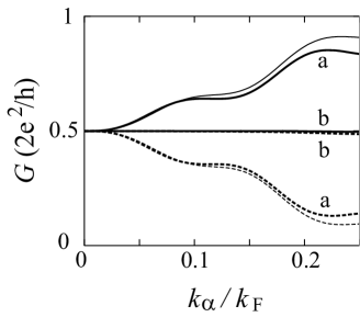
In our theory, the spin-flip by is important for the spin polarization during the transport from a narrow region to a wide region (). To confirm this idea, we examine two situations in Fig. 3: (a) is present only at or (b) only at . Indeed we observe the spin polarization in situation (a), whereas the polarization is not visible in situation (b).
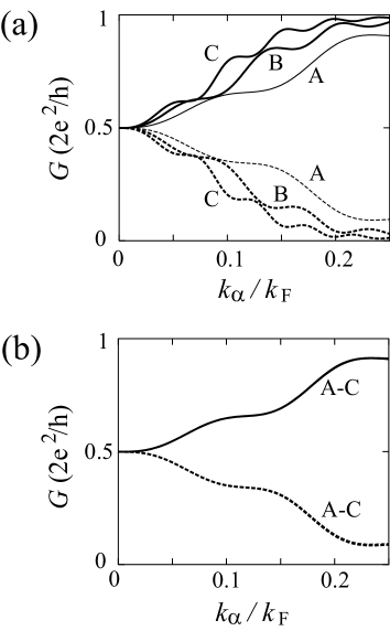
The adiabaticity of the spin-flip transition can be controlled by changing the shape of point contacts, e.g., in our model. With increasing , decreases in eq. (11) and hence in eq. (10) increases. As a result, a larger spin-polarization is expected. Figure 4(a) shows the numerical results with (A) , (B) , and (C) . The polarization ratio increases with an increase in , in accordance with our theory. In case (C), we observe a polarization of 60% with experimental values of in InGaAs heterostructures. In Fig. 4(b), we change with a fixed . The spin polarization is not influenced by , which is consistent with the previous discussion.
In conclusion, we have examined the ballistic transport through semiconductor point contacts in the presence of Rashba SO interaction. We have observed a spin-polarized current although the conductance is still quantized. The spin-polarization ratio is determined by the adiabaticity of the transition between subbands of different spins, which is characterized by eq. (11), during the transport from a narrow region to a wide region.
We have examined a quantum wire of width with a narrow constriction and demonstrated that the polarization ratio can be 60% in InGaAs heterostructures. Generally, a condition to generate the spin current is given by eq. (9). In GaAs heterostructures, is required with eVm ().[21] Our mechanism also works with Dresselhaus SO interaction
| (13) |
Then the output current is spin-polarized in the direction. If and coexist,[21] the eigenstates of determine the direction of spin polarization.
We make a few remarks. (i) The spin filtering effect is expected at the higher plateaus of conductance as well as at the first plateau. At the second plateau, for example, the crossings between modes and and those between and () work for the spin polarization if they appear below . Note that the crossing between modes and does not work since both modes are occupied just before the modes cross even at the second time. (ii) A steplike structure of the spin polarization is seen as a function of in Figs. 1(b) and 4. This reflects the number of crossings between and with below . With an increase in , more crossings appear below , which increases the spin-flip probability. (iii) In our model, the conductance seems to be influenced by the backward scattering for [eq. (12) does not hold]. Around , we observe the conductance plateaus with a small fluctuation, which might be due to some resonant states around the point contact with backward scattering. A spin current is still obtained with a polarization ratio of 90%. When the SO interaction is increased further, the plateaus begin to break. The investigation of this regime in more detail is beyond the scope of this paper.
Finally, we discuss the observation of the spin-polarized current produced by our mechanism. The spin polarization has to be directly measured since the conductance is not influenced. Possible experiments are an injection of the spin current into dilute magnetic semiconductors, an injection into a spin detector,[22, 23] or an optical measurement.[24] An indirect measurement may be available owing to the fact that mode is converted to upper modes, with , in the spin-flip processes. If the obtained current is injected into another point contact in the absence of SO interaction, the height of the first plateau is suppressed to when the polarization ratio is .
The authors gratefully acknowledge discussions with D. Matsubayashi, H. Yokouchi, J. Yamauchi, Y. Tokura and G. E. W. Bauer. This work was partially supported by a Grant-in-Aid for Scientific Research in Priority Areas “Semiconductor Nanospintronics” (No. 14076216) of the Ministry of Education, Culture, Sports, Science and Technology, Japan.
References
- [1] I. Žutić, J. Fabian and S. Das Sarma: Rev. Mod. Phys. 76 (2004) 323.
- [2] E. I. Rashba: Fiz. Tverd. Tela (Lenningrad) 2 (1960) 1224 [Solid State Ion. 2 (1960) 1109].
- [3] J. Nitta, T. Akazaki, H. Takayanagi and T. Enoki: Phys. Rev. Lett. 78 (1997) 1335.
- [4] A. A. Kiselev and K. W. Kim: Appl. Phys. Lett. 78 (2001) 775.
- [5] T. P. Pareek: Phys. Rev. Lett. 92 (2004) 76601.
- [6] T. Koga, J. Nitta, H. Takayanagi and S. Datta: Phys. Rev. Lett. 88 (2002) 126601.
- [7] Y. Středa and P. Šeba: Phys. Rev. Lett. 90 (2003) 256601.
- [8] J. Ohe, M. Yamamoto, T. Ohtsuki and J. Nitta: cond-mat/0409161.
- [9] B. J. van Wees, H. van Houten, C. W. J. Beenakker, J. G. Williamson, L. P. Kouwenhoven, D. van der Marel and C. T. Foxon: Phys. Rev. Lett. 60 (1988) 848.
- [10] A. Kawabata: J. Phys. Soc. Jpn. 58 (1989) 372.
- [11] G. Dresselhaus: Phys. Rev. 100 (1955) 580.
- [12] () is the Fermi wavenumber (energy) in the absence of SO interaction; . In its presence, we shift the Fermi energy by to keep the electron density constant.
- [13] D. Grundler: Phys. Rev. Lett. 84 (2000) 6074.
- [14] Y. Sato, T. Kita, S. Gozu and S. Yamada: J. Appl. Phys. 89 (2001) 8017.
- [15] T. Ando: Phys. Rev. B 44 (1991) 8017.
- [16] T. Ando and H. Tamura: Phys. Rev. B 46 (1992) 2332.
- [17] The lattice constant is chosen as when . A smaller value is required for when .
- [18] Equation (9) is an approximate expression that is valid for . It is exactly given by .
- [19] L. Landau: Phys. Z. Sowjetunion 2 (1932) 46.
- [20] C. Zener: Proc. R. Soc. London, Ser. A 137 (1932) 696.
- [21] J. B. Miller, D. M. Zumbühl, C. M. Marcus, Y. B. Lyanda-Geller, D. Goldhaber-Gordon, K. Campman and A. C. Gossard: Phys. Rev. Lett. 90 (2003) 76807.
- [22] J. A. Folk, R. M. Potok, C. M. Marcus and V. Umansky: Science 299 (2003) 679.
- [23] J. M. Elzerman, R. Hanson, L. H. Willems van Beveren, B. Witkamp, L. M. K. Vandersypen and L. P. Kouwenhoven: Nature 430 (2004) 431.
- [24] Y. K. Kato, R. C. Myers, A. C. Gossard and D. D. Awschalom: Nature 427 (2003) 50.