Charge transport through image charged stabilized states in a single molecule single electron transistor device
Abstract
The present paper gives an elaborate theoretical description of a new molecular charge transport mechanism applying to a single molecule trapped between two macroscopic electrodes in a solid state device. It is shown by a Hubbard type model of the electronic and electrostatic interactions, that the close proximity of metal electrodes may allow electrons to tunnel from the electrode directly into a very localized image charge stabilized states on the molecule. Due to this mechanism, an exceptionally large number of redox states may be visited within an energy scale which would normally not allow the molecular HOMO-LUMO gap to be transversed. With a reasonable set of parameters, a good fit to recent experimental values may be obtained. The theoretical model is furthermore used to search for the physical boundaries of this effect, and it is found that a rather narrow geometrical space is available for the new mechanism to be effective: In the specific case of oligophenylenevinylene molecules recently explored in such devices several atoms in the terminal benzene rings need to be at van der Waal’s distance to the electrode in order for the mechanism to be effective. The model predicts, that chemisorption of the terminal benzene rings too gold electrodes will impede the image charge effect very significantly because the molecule is pushed away from the electrode by the covalent thiol-gold bond.
I Introduction
Charge transfer processes of single electrons over Ångström distances between well defined molecular donor and acceptor moieties are ubiquitous in nature and they are extensively studiedno1 ; no2 . Classical examples include the photosynthetic reaction center, redox active enzymes and Kreutz-Taube complexes no1 ; no2 . For all of these processes, the contact to a temperature bath, molecular vibrations (phonons) and the reorganization of the molecular medium surrounding the CT process all play significant roles as expressed by Marcus theoryno3 ,
| (1) |
where is the rate of charge transfer and denotes the preexponential rate factor. The free energy, , where denotes the thermodynamic driving force of the reaction and the reorganization energy introduced by Marcus. In typical cases the reorganization energy will involve ions, and dipoles of the surrounding solvent as well as internal reorganization of the molecular CT-system.
By exchanging the donor or acceptor moiety with an electrode, centuries of electrochemical studies have advanced the understanding of charge transfer between a metal electrode and a redox active species in electrolyte solutionsno4 . Very recent experiments employing scanning tunneling microscopes under electrochemical control have further extended these studies to the single molecule levelno5 ; no6 .
As an extension of this historical development this paper also describes electron transfer processes on a single molecule level, but in the absence of a solvent. The experiment is based on a solid state devices in which a single molecule has been trapped between two metal electrodes in ultra high vacuum at 4 Kelvinno7 . Compared to previous measurements, temperature effects are hence suppressed and solvent and electrolyte effects are naturally absent. The presence of two metal electrodes in constant contact with the molecule, however, produces significant new effects resulting in a charge transport mechanism very different from that observed in classical photoinduced or electrochemically driven charge transfer systems. As described and analyzed in the following, we claim to have discovered a new charge transport channel mediated by image charge stabilized states lying in the band gap between the corresponding redox states in solution. The present paper emphasizes and expands on the theoretical treatment of this new phenomenon which was introduced in a recent paper describing the experimental possibility to visit several single molecule redox states in such a solid state deviceno7 . Since two historically rather segregated fields of science, “mesoscopic physics” and “redox chemistry”, are now coming together at the single molecule scale, we have chosen to describe the experiment reported in Ref. 7 in some detail followed by a introduction to the typical ”mesoscopic physics” description of the charge transport phenomena. Following this, we describe the detailed theory for the image charged states and finally make some prediction for how changes in molecular structure and device geometry should affect future experiments.
II Single molecule - single electron transistors
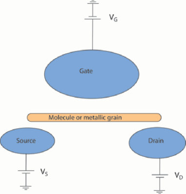
A transistor is an electronic device with 3 leads, source, drain and gate. The current from source to drain is controlled by either the voltage or the current through the gate. In the examples we shall consider in the present paper it is the voltage on the gate that is used as a control parameter. The concept is so broad that the electrochemical cell also is covered. The current runs from working electrode to the counter electrode and is controlled by the reference electrode. Our main emphasis is on the solid state device sketched in figure 1. Here an island of either a small metallic particle or a single molecule — hence the name “Single molecule transistor” — is placed between the source and and drain electrodes. These electrodes are typically made from gold. The construction is grown on top of the third gate electrode with an insulating layer in between to prevent any current to move through the gate. The island and the leads are hence only capacitively coupled to the gate.
The experiments we are going to consider here are carried out at 4 Kelvin, so quantum effects need to be taken into account. The most basic process is the transfer of an electron from one of the leads to the central island. At very low temperatures this is a quantum tunneling process, which is characterized by a tunneling matrix element. This corresponds to an energy, , or via the Heisenberg uncertainty principle to time scale . The property of the transistor depends on compared to other energies of the problem. The most relevant other energy scale is the change in electrostatic energy, , as the electron is moved to the island. In the so-called “strong coupling” limit, where , the electron will be delocalized and is described by a wavefunction, which has weights in both leads and on the island. The total charge on the island is simply not a good quantum number. In this limit standard Hartree-Fock or LDA calculations provide a good starting point for quantitative determination of e.g. the conductivities of the transistor. The other extreme, so-called “weak coupling”, is characterized by being the smallest relevant energy parameter of the problem. The important states of the system has the total charge of the island as a good quantum number. Electron transport is a very weak process, which can be described in perturbation theory, with the above tunneling processes as the perturbation. This is also the typical regime encountered for molecular charge transfer processes.
An important notion is that of “quantum coherence”. In principle all degrees of freedom, electrons, phonons, molecule position, etc., should be included when solving Schrödinger’s equation. In practice only a subsystem, e.g. the electrons, are considered. This will often, and certainly at low temperatures, be a good approximation, but after some characteristic time, the approximation breaks down and the effect of the environment (phonons, etc.) cannot be neglected. One way of describing this is to say, that the environment make a “measurement” on the electron system, and “collapses” it into one of a set of states with a certain probability. The Schrödinger equation for the electrons now takes over, with the collapsed state as its new initial state. The states to which the electrons collapses are particularly robust, and are the states which are relevant in the classical limit, where intricate quantum interference effects are suppressed. The nature of the coupling to the environment is such that these “classical” states has the total charge on the island as a good quantum number. The coherence time is strongly temperature dependent, rapidly decreasing with increasing temperature, and at not to high temperatures a master equation model, where one is only considering classical states and rates of transfer between these, is very effective at giving a good quantitative description.
The quantum states relevant for weak coupling are in fact “classical” (with a definite number of electrons on the central island), and the above mentioned master equation description is adequate. The electrons are being transported through the transistor through a series of ”classical” states one at a time, hence the name “Single Electron Transistor” (SET). Much of current research on Single Molecule, Single Electron Transistors is concerned with bridging the gap between the two limits of strong and weak coupling. A simple rule of thumb says, that if the conductivity of the device is much smaller than the conductance quantum then the transistor is in the weak coupling limit, while for a device with a much larger conductivity is in the strong coupling limit.
The experiments we are focussing on in this paper is certainly in the weak coupling limit. We will hence be emphasizing the nature of the ”classical states”, which are not as simple as one might at first think.
In each of the steps involved in the transport of an electron from source to drain energy conservation need to be satisfied. In the case where the central island is in fact a metal droplet, the determination of the total energy of a configuration is really an exercise in classical electrostatics, which we shall briefly review below. When the island becomes very small, like e.g. a single molecule, the determination of the total energy is a full quantum mechanical problem, where only part of the problem is electrostatics. What is needed in this case is a combination of classical electrostatics and quantum chemistry, and this will be the main result of this paper.
II.1 Orthodox SET theory
In the orthodox theory of Single Electron Transistors (see e.g. no11 ) all electrodes are considered to be classical conductors which, when charged, are coupled via a number of capacitances. Typically there is a capacitance, , coupling island and the source electrode, and capacitances , and , coupling the island the the drain and gate electrodes respectively. Implicity in such a model is the notion that a charge, on the island is split in three, , and , which are coupling only to their respective countercharges , and on the other electrodes. In reality all charges are of course coupled, and the more so in the relevant geometry of a very small island, where e.g. on the island and on the source electrode are physically very close, and both will couple to e.g. on the gate electrode. We hence set up a general classical scheme, where all couplings are treated on equal footing.
Assume now, that we have a set of conducting electrodes with charges . Each electrode is an equipotential with with electrical potential, . Poisson’s equation ensures, that there is a linear relation between charges and potentials:
| (2) |
where the coefficients, are entirely determined by the geometry of the system. The total electrostatic energy of the system is in this case given by
In the actual physical system the charges on the source, drain and gate electrodes are not given, rather it is the electrical potentials on these that are given and maintained e.g. by attached batteries. The charge on the island is still considered fixed, and the potential of the island is a variable depending on the potentials of the other electrodes and the charge on the island. Let us denote this charge, , and use Greek letters to denote the source, drain and gate electrodes. Regarding the potentials and the charge as independent variables we can solve (2) with respect to the electrode charges and the island potential. We get for the electrode charges
| (3) |
and for the island potential
| (4) |
Here the capacitance matrix is the inverse of . The dimensionless parameters , and the island capacitance are given by
| (5) |
The total electrostatic energy is in terms of these variables
| (6) |
Assume now, that the charge on the island is changed an amount . Then according to (3), the charge on the leads will change an amount
| (7) |
This gives a very simple interpretation of the three parameters, as the fraction of counter charge on the electrodes induced by the extra charge on the island.
For a current to flow from source to drain there are two possible scenarios: a) first an electron moves from source to island, and then from island to drain or b) first an electron moves from island to drain and then an electron moves from source to island. In general the battery work involved in the first step of scenario a) will be
| (8) | |||||
where we have introduced the average of the source and drain potentials, , and their difference, . Likewise the work provided in the first step of b) where an electron moves from island to drain is
| (9) |
The total battery work in both scenarios is the sum of and , which is , so if then the overall process is energetically possible. The first step, however, is not necessarily possible.
Consider a situation where are electrons on the island, i.e. , and where the average potential of the source and drain potentials is equal to the ground potential, i. e. zero. The change in electrostatic energy in process a) will be
| (10) |
The battery work in the first step will be
| (11) |
If i.e. if
| (12) |
then the process is possible, and current will flow. If then the step will happen even for . This means that an extra electron will move permanently to the island, and the analysis should be repeated with .
In the first step in the b) process electrostatic energy will be
| (13) |
The battery work will now be
| (14) |
If , i.e. if
| (15) |
we will have current flowing according to scenario b). For then the first step of moving an electron from island to drain will be permanent, and we should replace by .
The situation is summarized in the following figure.
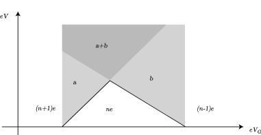
The width of the white diamond is given by , while the two slopes are given by and . From these parameters, which can be determined experimentally, we can read of the following electrostatic parameters:
| (16) |
It is easy to show, that is the ratio of the height of the diamond to its width, which simplifies the determination of this important parameter if there is experimental access to the full diamond.
II.2 Beyond orthodox SET. Single molecule transistors
The orthodox theory of Single Electron Transistors is based on a classical electrostatic conductor model of both electrodes and the central island. In a Single Molecule Transistors, the central island is replaced by a molecule, who’s electronic structure and total energy is determined by quantum mechanics. This e.g. means that the excess energy in the gray areas of Fig. 2, cannot necessarily be deposited in the molecule due to the discrete nature of the molecular energy levels. Another problem, which is particularly acute in the recent experiments on Single Molecule Transistors where the molecule is OPV5. Here the coupling between electrons on the molecule and induced charges in the electrodes — the so-called image charges — will significantly change the electronic structure of the molecule, and hence affect the transport through the transistor. These effects call for a generalization of the orthodox model, and this is the purpose of the following discussion.
The charge density, , on the molecule will induce charges in the electrodes and change potential of these. In principle is a quantum mechanical operator, but in what follows we shall use the Hartree approximation for this, since the effects we are after can indeed be captured in this approximation. The metallic electrodes are still described as classical electrostatic conductors. For good conductors with a high electron density this is certainly a good approximation, as discussed by Lang and Kohnno9 .
The potential of electrode with label ( still referring to either source, drain or gate), now becomes
| (17) |
where the parameters are characteristic for the geometry of the electrodes without the molecule. represent the coupling between the molecular charge density and the so-called canonical charge density, , of a unit charge added to electrode :
| (18) |
The total electrostatic — or Coulomb energy — in this case now becomes
| (19) | |||||
where is the charge density induced on the surfaces of the electrodes. In contrast to the canonical charge densities, this “image” charge density is quite localized to a region on the electrodes close to the molecule. In fact, is linearly related to , so we can write
| (20) |
where the kernel is given by the geometry of the system. We use a minus in the definition, since is describing an image charge. If we insert (20) into (19) we get the final version of the total electrostatic energy
| (21) | |||||
where the kernel is given by
| (22) |
So far we have considered the charge distributions as given. They are determined by several factors. The total charge on the molecule can be considered fixed and given, but the actual distribution is determined in a fully quantum mechanical calculation. The charge distribution on the molecule is given in terms of the one-electron wavefunctions (e.g. the wavefunctions appearing in the Kohn-Sham equations of the Density Functional Theory):
| (23) |
where is the electron charge and is the charge density of the nuclei. The potential energy term in Schrödinger’s equation includes the potential from the other charges in the problem and can be obtained as
| (24) | |||||
where the first term is the interaction with the charges on the electrodes, and the second is the Hartree term of the molecule plus interaction with image charges. In deriving this result we have assumed that the electron system of the metal electrodes are very fast degrees of freedom, which instantaneously respond to changes in the electron distribution of the molecule.
The total energy of the molecule, i.e. the eigenvalue of the many body Schrödinger equation will hence include the two last terms of the total electrostatic energy from equation (21). The total energy of the entire configuration, i.e. including both electrostatic energy stored in the charged electrodes and the total energy of the molecule in this particular environment becomes
| (25) |
where the last term is the total energy of the molecule, including coupling to electrodes and image charges.
In the physical situation we have in mind, the electrodes are kept at fixed potential — maintained by “batteries”. This means that the charge distributions are dependent variables, determined by the geometry, by the fixed potentials , and by the molecular charge, . As in the orthodox theory we shall eliminate the total charges from the problem. We get
| (26) |
The potentials depends on the actual charge distribution on the molecule, which is not easily accessible. In order to proceed further we need to make some simplifying assumptions. If the electrodes are quite far from the molecule, or if the electrodes have small potential differences, then the electrical potential due to the electrode charges will be almost constant in the region of the molecule, and the contribution to the total electrostatic energy from this potential is well approximated by
| (27) |
where is the total charge on the molecule, and
| (28) |
which is independent of in the approximation we use. We shall write the total molecular energy as
| (29) |
Here is the total molecular energy, obtained from the quantum calculations, where the first term in Eq. (24) is omitted. In the concrete cases we are considering in this paper, the gate electrode is reasonably far away and if the source and drain electrodes are kept at the same or only small potential differences, then the approximation should be OK.
The rest of the analysis proceeds as in the orthodox theory. The electrode charges, , are eliminated and we consider two processes a) and b) that can transfer an electron from source to drain. The a) process is possible if the electrode potentials satisfy the inequality
| (30) |
where
| (31) |
with a different capacitance however:
| (32) |
The reason for this change in capacitance is, that the large self interaction of the charge on the island, , is in the molecular case contained in the term via the through the electron-electron interaction term (the last term of Eq. (21)). Likewise, the b) process is possible if
| (33) |
with
| (34) |
Again we obtain a diamond structure like in Fig. 2, and the fractional charge parameters are determined by the slopes of the diamond. The width of the charge diamond is different. It will be given by
| (35) |
This formula is the important end result of the general analysis. To summarize the discussion so far, we can say that the orthodox theory has a very wide domain of applicability, which includes a situation, where image charge effects are relevant. These image charges are not to be considered part of the electrodes, but can be viewed as extensions of the molecule, and be included in the quantum calculation of the molecular electronic states.
III OPV5
In the past few years there has been a drive to experimentally realize single molecule transistors. Several strategies has been used, and in the literature now has reports of many such transistorsno8 . Here we shall focus on the work of Kubatkin et al.no7 who very carefully has grown two gold leads on top of a gate electrode spatially separated from the rest of the system by an insulating Al2O3 layer. By in situ monitoring the source-drain conductance while depositing gold, it is in fact possible to obtain a source-drain distance of approximately 2 nm. With this electrode geometry the organic oligo-p-phenylenevinylene derivative, OPV5, with 5 benzene rings in a chain, which in each end is terminated by sulfur and a tertiary butyl group. At somewhat elevated temperatures ( Kelvin) the molecule diffuse on the surface until a increase of conductance is suddenly observed. This is interpreted as the realization of an OPV5 forming an electronic bridge between the source and drain electrodes. The length of OPV5 is 3.2 nm, so this is physically possible. Temperature is lowered to liquid Helium temperatures, and a full electronic characterization of the transistor is made. It shows a very beautiful set of no less than 7 or 8 full SET diamonds. The conductance in the current carrying modes is well below the conductance quantum, so the theory of the previous section should apply.
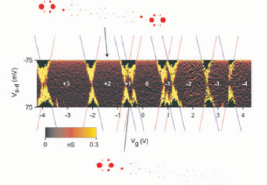
The first thing to do is to establish the conversion factor, , between the gate voltage axis and energy. It is obtained from the slopes of the diamonds trough Eq. (II.1). The fact, that all observed slopes are identical gives support to the theoretical picture presented. The analysis gives .
What is to be expected? First a comparison to electrochemical experiments is made. These experiments are quite analogous to the SET experiments. In electrochemistry we have electrons passing from working to counter electrodes controlled by a third reference electrode. In solution diffusing OPV5 molecules act as electrolyte and electron shuttles, carrying electrons between electrodes. The shuttle only works if a the molecule has an affinity level aligned with the source electrode Fermi energy. By changing the voltage on the reference electrode, the electronic chemical potential of the solution — including the OPV5 molecules — the experiment can map electronic levels of the molecule. Two sets of redox states are found, with a quite large gap, 2.5 eV, between them. This is also the value of the HOMO-LUMO gap measured directly by optical absorption
As a first attempt at calculating the width of the diamond we will assume, that the charge on the molecule is uniformly distributed over the carbon atoms. In this case the width of the is the HOMO-LUMO gap of the unperturbed molecule. This is a more than a factor of 10 larger than the observed width, which is meV. We therefore have to conclude, that severe relaxation effects are taking place when electrons are added or subtracted the OPV5 in the present geometry. A possible relaxation mechanism is the structural deformation of the molecule which takes place when adding an electron. This, however, only amounts to an energy of approximately 200 meV no10 , which has no chance of explaining the large effect observed.
We are thus led to consider the possibility of direct electrostatic coupling to the nearby source and drain electrodes. This in turn has forced us to reconsider the basic electrostatics in a Single Electron Transistor with a very small central island with quantized energy levels. This is what was presented in the previous section. In order to make a quantitative estimate of the size of image charge effects we need a somewhat realistic model of the molecule, where these effect can be included without to much effort. We have chosen to describe OPV5 using the Hubbard model. The important orbitals of the OPV5 are the 38 -orbitals of the carbon atoms, and the coupling between nearest neighbor atoms are given by a matrix element (or in the quantum chemistry literature). The value of this is well established, and is eV. This e.g. reproduce the optical HOMO-LUMO gap. We further need a term which describe the Coulomb repulsion among electrons on the molecule. The most important term is here the intra atom repulsion, which is parameterized by the so-called Hubbard . In the calculations below, the value is taken to be eV. There is no agreed upon value of in the literature. It is an effective parameter, which depends on the chemical environment of the carbon atom in question.
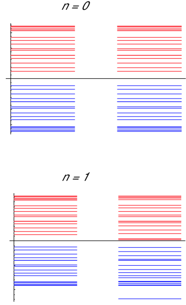
It is not feasible to do exact calculations, even using the simplifications of the Hubbard model. We are doing a mean field calculation, where the spin densities and ( being an atom index) are determined selfconsistently. In the neutral OPV5 molecule far away from all electrodes, the spin densities are uniform, , resulting in the single electron spectrum shown in Fig. 4. We note the HOMO-LUMO gap of 2.5 eV. If an electron is removed from the molecule, the new densities are still uniform, and the resulting spectrum is unchanged (except for a simple energy shift). This is actually a non-trivial result. For larger ’s one finds non-uniform spin and charge densities, which is a general feature of strongly correlated electron systems. Calculations for values of so large, that added (or removed) electrons form a state with an inhomogeneous charge distribution, show that the calculated width of the diamond is still several electron volts (depending on the exact value of ). We conclude, that a molecule unperturbed by the electrodes — except for a constant shift of the electrochemical potential — cannot account for the observations.
The first attempt of including the effect of the metallic electrodes, is to model an electrode as a half infinite conducting plane — the standard geometry of undergraduate electrostatics. We have carried out calculations for the a molecule placed with varying distances and angles with respect to the model electrode. For all realistic parameters (e.g. distances larger than 1.5 Å) we find no inhomogeneous charge distributions, and hence no drastic renormalization of the diamond width. The reason is, that only the carbon atom closest to the electrode feel a potential image charge, and that reduces the effect to negligible changes.
The actual electrodes are in fact heaps of gold atoms, and in the final geometry we have considered, the benzene rings at the ends of the molecule is lying flat on the electrode (within approximately a van der Waals distance), so that a charge imbalance on any of the six carbon atoms of these rings will couple relatively strongly to its image charge in the electrodes. Calculations now show a strong perturbation of the electronic structure of the moleculeno12 . By varying only the distance between molecule and electrode we are able to fit the three central diamonds, which involves redox states of the molecule. The actual distance between the benzene ring and the mirror plane of the gold electrodes chosen to fit the data is 2.2 Å, which is quite realistic, given the known van der Waals radius of benzene. In figure 3 we also show the electron densities of some of these states. For the state the charge pile up at the end benzene ring of the molecule. The state, which is quite close in energy, the two charges occupy each end of the molecule. There are two such states, but it turns out that the singlet state (spin = 0) is approximately 70 meV lower in energy, so we propose that this is the relevant state to the experiment. The one electron energy spectra, which enters the calculations, are shown in Fig. 4. We see, that they are completely scrambled, and no intuition is to be gained by only considering these spectra. Only the total energies carry the relevant information.
IV Conclusion
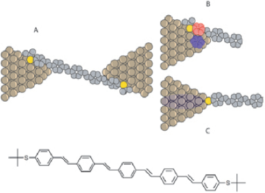
In conclusion we find, that the image charge effects can be involved in the physics of Single Molecule Transistors. It requires, however, a special geometry. By varying the end groups of the molecule (and other molecules of the OPV family) we expect a geometry change that will remove the strong perturbation due to image charges. If e.g. the tertiary butyl group is removed so that the Sulfur atom binds directly to the Gold electrodes the possibility of having the end benzene ring couple electrostatically to the electrode is severely impeded and the diamond should become approximately a factor of 10 greater corresponding to the unrenormalized HOMO-LUMO gap. These different situations are summarized schematically in Fig. 5, where Fig. 5A - B show a likely orientation of the molecule in the device realized in the experiment by Kubatkin et al. in which the terminal thiol capped benzene ring is protected by a tertiary butyl group. Fig. 5B illustrate the image charge as a blue shadow of the “red” charges in the molecule. In this case all of the atoms in the terminal benzene ring are affected by image charges and calculations show a strong localization of the charge on this ring, as also seen in Fig. 3. The van der Waal’s nature of the contact between the physisorbed molecule and the electrode, with the hydrogen atoms at the edge of the benzene ring being the likely contact region, prevent a strong electronic coupling between the electron system and the electrode. In turn this results in a relatively large tunneling barrier and Coulomb blockade behavior as experimentally observedno7 . Shown as Fig. 5C is the likely orientation of the same terminal benzene when it is deprotected allowing the terminal thiol to form a chemical bond to the gold electrode. In this case the benzene ring is pushed away from the surface of the electrode by the covalent thiol bond. Our calculations show that image charge effects are seriously impeded in this case, and we therefore predict that these effects will play a minor role. Interestingly, the electronic coupling between the electrode and the molecule, now mediated by a covalent bond, is expected to be stronger then the coupling mediated by the van der Waals contact discussed above.
Taken together the above analysis reveal an intricate relation between the details of the molecule-electrode contact and the resulting effective charge transfer channels. The relation resembles the competition between charge delocalization and localization often discussed in terms of the Hubbard parameters and . In our case, however, the electron localization is driven by image charge effects rather than electron-electron repulsion. In the special case described in the present paper, it is shown that image charges can influence this electronic instability in direction of the localized regime very significantly. The key parameter controlling the magnitude of this effect is the distance of the atoms in the molecule to the electrode surface. This parameter is independent of the degree of electronic overlap between the electrons in the molecule and electrode, which tends to favor coherent transport through delocalized states. A series of experiments in which these two parameters are varied independently are currently under investigation in our laboratories, and we expect a series of new phenomena to be reveled as we systematically map the properties of single molecule devices in which both delocalized coherent transport and sequential electron hopping between localized states are active.
References
- (1) Balzani V, Scandola, F. ”Supramolecular Photochemistry” Ellis Horwood Series in Physical Chemistry (1991).
- (2) Alexander M. Kuznetsov, Jens Ulstrup: Electron Transfer in Chemistry and Biology: An Introduction to the Theory. John Wiley and Sons (1998).
- (3) Marcus R.A., Ann. Rev. Phys. Chem. 15, 155 (1964).
- (4) Lund. H, Hammerich O. (Eds.) Organic Electrochemistry 4.th Edition, Marcel Dekker Inc., N.Y. Basel (2001).
- (5) Hansen AG, Zhang JD, Christensen HEM, Welinder AC, Wackerbarth H, Ulstrup, Israel Journal of Chemistry 44 (1-3), 89-100 (2004), Kuznetsov AM, Ulstrup Journal of Electroanalytical Chemistry 564 (1-2), 209-222 (2004), Kuznetsov AM, Ulstrup, Journal of Chemical Physics, 116 (5), 2149-2165 (2002).
- (6) Alessandrini A, Gerunda M, Canters GW, Verbeet MP, Facci P, Chem. Phys. Lett. 376 (5-6), 625 (2003).
- (7) Kubatkin, S., Danilov, A., Hjort, M., Cornil, J., Brèdas, J-L., Stuhr-Hansen, N., Hedegård, P. and Bjørnholm, T., Nature 425, 698-701 (2003).
- (8) Park H, Park, J, Lim AKL, Anderson EH, Alivisatos AP, McEuen, PL, Nature 407, 57 (2000); Liang WJ, Shores MP, Bockrath M, Long, JR, Park H, Nature 417, 725 (2002); Park J, Pasupathy AN, Goldsmith JI, Chang C, Yaish Y, Petta JR, Rinkoski M, Sethna JP, Abruna HD, McEuen PL, Ralph D, Nature 417, 722 (2002); Mayor M, Weber HB, Reichert J, Elbing M, von Hanisch C, Beckmann D, Fischer M, Ang. Chemie. Int. Ed. 42, 5834 (2003); Yu LH, Natelson D, Nano Letters 4, 79 (2004); Wassel RA, Gorman CB, Ang. Chemie. Int. Ed. 43, 5120 (2004); Natelson D, Phys. Rev. Lett. 93, 266802 (2004).
- (9) Lang ND and Kohn WD, Phys. Rev. B 7, 3541 (1973).
- (10) Geskin VM, Cornil J and Brédas, Chem. Phys. Lett. in press (2005).
- (11) van Houten H, Beenakker CWJ, and Staring AAM in Single Charge Tunneling and Coulomb Blockade Phenomena in Nanostructures, Ch. 5, Plenum New York (1992).
- (12) In the calculations presented in this paper, we have not made a complete calculation of the kernel . Rather we have made a constant shift of the atomic energies of all the orbitals of the first (or last) bezene ring. The shift is proportional to the net charge on the benzene ring, and the distance dependence is determined by a simple model, where a ring of charge is placed above a metallic plane. Such an approximation will have all the correct features of the exact kernel .