Dept. of Physics and Center for Soft Matter Research, New York University, New York, NY 10003
Colloids Optical trapping Rheology of colloids
Colloidal hydrodynamic coupling in concentric optical vortices
Abstract
Optical vortex traps created from helical modes of light can drive fluid-borne colloidal particles in circular trajectories. Concentric circulating rings of particles formed by coaxial optical vortices form a microscopic Couette cell, in which the amount of hydrodynamic drag experienced by the spheres depends on the relative sense of the rings’ circulation. Tracking the particles’ motions makes possible measurements of the hydrodynamic coupling between the circular particle trains and addresses recently proposed hydrodynamic instabilities for collective colloidal motions on optical vortices.
pacs:
82.70.Ddpacs:
87.80.Ccpacs:
83.80.HjA beam of light with helical wavefronts [1] focuses to a ring-like optical trap known as an optical vortex [14, 24, 11], which not only traps micrometer-scale objects, but also exerts torque on them [13, 10, 25]. Since their introduction nearly a decade ago, optical vortices have been used to probe the nature of photon orbital angular momentum [10, 25, 20, 19, 5] and to create microoptomechanical devices such as rotary pumps and mixers [6, 16]. In this paper, we demonstrate a new class of microoptomechanical devices resembling Couette cell rheometers that are based on optimally matched pairs of concentric optical vortices [12] created with the holographic optical tweezer technique [7, 23, 18, 8, 6]. These paired-vortex machines constitute a useful model system for studying many-body colloidal hydrodynamics.
The field, , in an optical vortex is characterized by a transverse phase profile , where is a polar coordinate in a plane normal to the optical axis and is an integer winding number, also known as a topological charge, that characterizes the beam’s helicity. The amplitude profile typically is that of a conventional TEM00 laser beam whose wavefronts are imprinted with to create the helical mode. In our implementation, a liquid crystal spatial light modulator (Hamamatsu X7550 PAL-SLM) encodes computer-generated holograms on the wavefronts of a beam from a frequency-doubled diode-pumped Nd:YVO4 laser (Coherent Verdi). The modulated beam is relayed to a microscope objective lens (Zeiss 100 NA 1.4 oil immersion S-Plan Apochromat) mounted in an inverted optical microscope (Zeiss S100-TV), which focuses it into an optical vortex.
The same objective lens can be used to create images of objects interacting with the projected optical vortex. Provided that care is taken to minimize or correct for aberrations in the optical train, this system is capable of trapping one or more colloidal particles and circulating them at up to several hundred revolutions per minute.

If the radial amplitude profile varies slowly across the optical train’s aperture, , then the focused optical vortex takes the form of a ring of radius [5, 26]
| (1) |
surrounded by a hierarchy of concentric diffraction rings. Here, is the objective lens’ focal length and arises from the SLM’s pixellated structure [5].
Very recently, Guo et al. [12] showed that the extraneous diffraction rings can be ascribed to rays of light emanating from the central region of the phase mask, , while the principal ring is projected from the outer region. This explains why optical vortices with winding numbers exceeding can be projected with a pixellated SLM [6, 5, 26] even though features in the associated phase mask exceed the device’s Nyquist wavenumber near the optical axis. It also suggests that the generally undesirable diffraction rings can be suppressed by imposing an annular radial profile on the source beam, where is the Heaviside step function. The outer limit, , replaces the system’s aperture in Eq. (1) to set the optical vortex’s radius, and the inner limit, , can be adjusted to optimize the optical vortex’s radial profile. Following Ref. [12], the optimal inner limit that eliminates diffraction rings without degrading the vortex’s principal ring is approximately given by
| (2) |
where is the -th zero of the derivative of the Bessel function . Guo et al. [12] point out that the principal ring’s intensity is diminished when exceeds , although its radius remains unchanged.
The unused central region of an optimized vortex’s phase mask can be filled with a phase profile encoding one or more additional optimized optical vortices. In this case, the inner limit of the first phase mask establishes the maximum outer limit of the next, and thereby helps to determine the projected radius of the second vortex through Eq. (1). Depending on its winding number , the secondary optical vortex can be either larger or smaller than the first. The optimal inner limit of the secondary vortex’s annular phase mask again is determined by Eq. (2). The number of vortices that can be projected in this way is limited by the size and resolution of the SLM.
A typical phase mask encoding two concentric optical vortices is shown in Fig. 1(a), and the associated pattern of traps appears in Fig. 1(b). The two optical vortices’ relative intensities can be tuned by adjusting their annular phase masks’ inner limits. Their relative radii can be adjusted by setting both the outer limits and the topological charges. The combination of relative intensity, geometry and topological charge helps to establish the relative torques that the concentric focused rings of light exert on trapped objects. The resulting tunability is very helpful for controlled studies of driven colloidal hydrodynamics. Here we have projected two concentric vortices of topological charges and , with focused principal rings formed at and respectively.
In practice, the part of the input beam passing through featureless regions of the composite phase mask in Fig. 1(a) propagates along the optical axis and focuses to a conventional optical tweezer in the middle of the field of view. We have eliminated this undiffracted spot with a spatial filter [15] and displaced the concentric vortices by adding a phase function
| (3) |
where the in-plane wavenumbers, and , set the in-plane displacement and the axial wavenumber displaces the focal plane along the optical axis [18, 6]. Figure 1(a) shows without for clarity. When combined with appropriate control and correction of aberrations, these displacements yield the comparatively circular and uniformly bright rings in Fig. 1(b). The rings were imaged at low laser intensity by placing a mirror in the microscope’s focal plane and projecting the reflected light along the microscope’s imaging train to a charge-coupled device (CCD) camera (NEC TI-324AII). Each ring can trap and circulate a single colloidal particle, and the pair can organize multiple particles into concentric circulating rings, as shown in the bright-field image in Fig. 1(c).
Our samples consist of monodisperse polystyrene sulfate microspheres (Bangs Laboratories L030305C) in diameter dispersed in a layer of water thick sandwiched between the parallel glass surfaces of a microscope slide and a #1 cover slip. The concentric optical vortices’ axial intensity gradients were not strong enough to overcome radiation pressure and trap these particles stably in the axial direction. Consequently, we focused the traps near the upper surface, which prevented the particles from escaping while permitting them to circulate freely around the rings.
The concentric vortices’ circumferential intensity variations were estimated by fitting the radial intensity profile in images such as Fig. 1(b) to the predicted cross-section [26]. Azimuthally-resolved intensity variations, plotted in Fig. 1(d), are smooth enough that particles do not become trapped in localized hot spots [5]. We measured the individual optical vortices’ transport properties by loading a single particle into one of the rings and tracking its motions [4]. Consistent results were obtained for laser powers ranging from to , with the measured single-particle speeds scaling nearly linearly with power. The data from all runs were normalized by power and combined into the results plotted in Fig. 1(e). Somewhat paradoxically, regions of minimum circulation speed appear to be correlated with the brightest regions of the ring, where the optically-induced torque should be greatest. This demonstrates that the intensity variations around each ring’s circumference result in attractive optical gradient forces. The importance of this gradient attraction relative to the torque exerted by the photon’s orbital angular momentum confirms that the particles absorb a very small fraction of the incident photons.
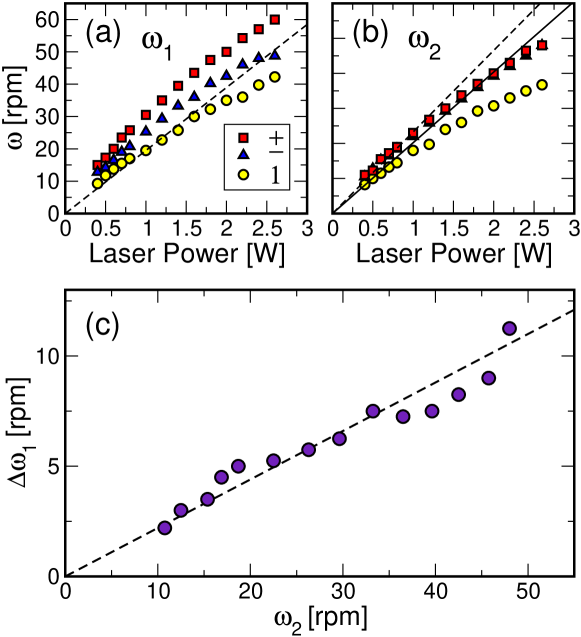
Despite the particles’ preference for brighter regions, there is no evidence of circumferential trapping, and we are justified in averaging the circulation speed over angles to characterize the rings’ overall performance. The mean circulation speed for a single sphere on the outer and inner rings is plotted as a function of laser power in Figs. 2(a) and 2(b). Departures from linearity in the power dependence are comparable to our measurement error over the range, and can be ascribed to increased hydrodynamic coupling to the upper glass surface with increasing radiation pressure. Consistent results for both rings were obtained for and .
The hydrodynamic drag on a single sphere of radius moving at speed through an unbounded fluid of viscosity is , where is the Stokes drag coefficient. Adding particles to one ring reduces the drag on each sphere through the familiar drafting effect. For spheres equally spaced around a ring of radius , the modified single-sphere drag coefficient is [22]
| (4) |
where is the angular separation between spheres and , and is their spatial separation. We can use this result as a starting point to predict the filled rings’ circulation rates based on our single-particle measurements.
Coupling between the two rings should increase the drag on spheres in counter-rotating rings, , and reduce it for co-rotating rings, . This is indeed the case, with the effect being considerably more pronounced for the inner ring (Fig. 2(a)) than the outer (Fig. 2(b)). The predictions of Eq. (4) are plotted as dashed lines in these figures. Although Eq. (4) adequately describes the motions of the outer ring of spheres, it substantially underestimates the hydrodynamic coupling among particles on the inner ring. This might result from the nonuniform separation between spheres as they circumnavigate the inner ring’s intensity variations, which are more pronounced than on the outer ring, Fig. 1(d) and (e).
Even this level of agreement may be coincidental, however. The spheres in this experiment are separated from a nearby wall by a center-to-surface distance that is not accounted for by Eq. (4). The no-slip boundary condition on the wall modifies the spheres’ far-field flow patterns, reducing their mutual hydrodynamic coupling [9]. At the level of the stokeslet approximation [21], the equivalent wall-corrected result to is
| (5) |
where
| (6) |
is the single particle’s wall-corrected Stokes drag coefficient. This still shows an overall reduction in the drag due to drafting, but to a substantially reduced degree. The modified functional dependence on the inter-particle separation suggests that the spectrum of instabilities for such symmetric configurations [22] also will be modified by coupling to bounding surfaces. A fit of Eq. (5) to the results for the outer ring, plotted as a solid curve in Fig. 2(b), yields . This is consistent with the measured sphere-wall separation.
Even at this low level of approximation, the predicted reduction in drag accounts for the increased circulation rates when five particles are loaded onto the inner ring and twelve onto the outer, as shown in Fig. 1(c). The circulation rates on the outer ring are increased by 30% (Fig. 2(b)), and on the inner ring by 47% when the two rings are co-rotating and by 22% when they are counter-rotating (Fig. 2(a)), over the range of laser powers applied.
The data in Fig. 2 also reveal that the many-body hydrodynamic coupling in this system depends on whether the two rings of spheres are co-rotating () or counter-rotating (). The inner ring, in particular, circulates 20% faster in the co-rotating configuration. The difference in the inner ring’s circulation rate increases with laser power, but is unlikely to result from optical interactions directly. Rather, the trend can be ascribed to the increasing circulation rate of the outer ring with increasing laser power, as shown in Fig. 2(c). Parameterizing by is reasonable because the outer ring’s circulation rate depends only weakly on the relative circulation direction.
We may capture this behavior semi-quantitatively by ignoring the concentric rings’ detailed structure and treating them instead as concentric cylinders in a Couette geometry. In this case, the drag-induced torque between the cylinders is [17]
| (7) |
where is the effective height of the cylinders. The change in frequency upon switching the relative circulation direction is then
| (8) |
Fitting to the data in Fig. 2 yields . For continuous cylinders with no-slip boundary conditions, we would expect . The difference can be ascribed to the rings’ roughly 25 percent filling factors, which establish partially sliding boundary conditions.
This simple model’s success suggests that the detailed distribution of particles on the rings plays a minor role in establishing the inter-ring hydrodynamic drag, although the discreteness itself is very important. Consequently, colloidal particles in concentric optical vortices should provide a model experimental system for studying how surface roughness influences hydrodynamic boundary slip [2, 3], with the degree of surface structure being determined by the particle size and filling factors.
We have demonstrated that optimized optical vortices can be used to trap and circulate fluid-borne colloidal particles. Concentric circulating rings of particles constitute a model test-bed for studying many-body hydrodynamic coupling in mesoscopic systems. Improvements in the optimized optical vortices’ uniformity will make possible detailed investigations of hydrodynamic instabilities in driven many-particle systems. More immediately, the system of optically driven colloidal rings shows promise as a microoptomechanical Couette shear cell, with potential applications in lab-on-a-chip systems.
Acknowledgements.
This work was supported by the National Science Foundation through Grant Number DMR-0451589 and Grant Number DBI-0233971.References
- [1] \NameAllen L., Beijersbergen M. W., Spreeuw R. J. C. Woerdman J. P. \REVIEWPhys. Rev. A4519928185.
- [2] \NameBarrat J.-L. Bocquet L. \REVIEWPhys. Rev. Lett.8219994671.
- [3] \NameBonaccurso E., Butt H.-J. Craig V. S. J. \REVIEWPhys. Rev. Lett.902003144501.
- [4] \NameCrocker J. C. Grier D. G. \REVIEWJ. Colloid Interface Sci.1791996298.
- [5] \NameCurtis J. E. Grier D. G. \REVIEWPhys. Rev. Lett.902003133901.
- [6] \NameCurtis J. E., Koss B. A. Grier D. G. \REVIEWOpt. Comm.2072002169.
- [7] \NameDufresne E. R. Grier D. G. \REVIEWRev. Sci. Instr.6919981974.
- [8] \NameDufresne E. R., Spalding G. C., Dearing M. T., Sheets S. A. Grier D. G. \REVIEWRev. Sci. Instr.7220011810.
- [9] \NameDufresne E. R., Squires T. M., Brenner M. P. Grier D. G. \REVIEWPhys. Rev. Lett.8520003317.
- [10] \NameFriese M. E. J., Enger J., Rubinsztein-Dunlop H. Heckenberg N. R. \REVIEWPhys. Rev. A5419961593.
- [11] \NameGahagan K. T. Swartzlander G. A. \REVIEWOpt. Lett.211996827.
- [12] \NameGuo C.-S., Liu X., He J.-L. Wang H.-T. \REVIEWOpt. Express1220044625.
- [13] \NameHe H., Friese M. E. J., Heckenberg N. R. Rubinsztein-Dunlop H. \REVIEWPhys. Rev. Lett.751995826.
- [14] \NameHe H., Heckenberg N. R. Rubinsztein-Dunlop H. \REVIEWJ. Mod. Opt.421995217.
- [15] \NameKorda P. T., Spalding G. C., Dufresne E. R. Grier D. G. \REVIEWRev. Sci. Instr.7320021956.
- [16] \NameLadavac K. Grier D. G. \REVIEWOpt. Express1220041144.
- [17] \NameLandau L. D. Lifshitz E. M. \BookFluid Mechanics \PublPergamon Press, New York \Year1959.
- [18] \NameLiesener J., Reicherter M., Haist T. Tiziani H. J. \REVIEWOpt. Comm.185200077.
- [19] \NameO’Neil A. T., MacVicar I., Allen L. Padgett M. J. \REVIEWPhys. Rev. Lett.882002053601.
- [20] \NameO’Neil A. T. Padgett M. J. \REVIEWOpt. Comm.1852000139.
- [21] \NamePozrikidis C. \BookBoundary Integral and Singularity Methods for Linearized Viscous Flow \PublCambridge University Press, New York \Year1992.
- [22] \NameReichert M. Stark H. \REVIEWJ. Phys.: Cond. Matt.162004S4085.
- [23] \NameReicherter M., Haist T., Wagemann E. U. Tiziani H. J. \REVIEWOpt. Lett.241999608.
- [24] \NameSimpson N. B., Allen L. Padgett M. J. \REVIEWJ. Mod. Opt.4319962485.
- [25] \NameSimpson N. B., Dholakia K., Allen L. Padgett M. J. \REVIEWOpt. Lett.22199752.
- [26] \NameSundbeck S., Gruzberg I. Grier, D. G. \REVIEWOpt. Lett.2004accepted for publication.