Detecting Entanglement Using a Double-Quantum-Dot Turnstile
Abstract
We propose a scheme based on using the singlet ground state of an electron spin pair in a double-quantum-dot nanostructure as a suitable setup for detecting entanglement between electron spins via the measurement of an optimal entanglement witness. Using time-dependent gate voltages and magnetic fields the entangled spins are separated and coherently rotated in the quantum dots and subsequently detected at spin-polarized quantum point contacts. We analyze the coherent time evolution of the entangled pair and show that by counting coincidences in the four exits an entanglement test can be done. This setup is close to present-day experimental possibilities and can be used to produce pairs of entangled electrons “on demand”.
pacs:
03.65.Ud, 03.67.Mn, 73.63.KvOne of the challenges in present-day condensed-matter nanophysics
is the controlled production of high-fidelity entangled states of
separated electrons for use in quantum information processing.
Such an operation is difficult, largely because of the strong
interactions between electrons, making it difficult to isolate and
coherently manipulate (single) entangled pairs. But a number of
promising ideas have recently been put forward, involving Cooper
pairs extracted from a superconductor leso01 ; samu03 ,
two electrons in a single or double quantum
dot loss00 , electrons scattered at a
local magnetic impurity cost01 , or electrons scattered at
one or more beam splitters been03 . Several of these
ideas have led to explicit proposals for detection of entangled
pairs via a test of Bell’s inequality by measuring
noise samu03 ; chtc02 ; been03 .
Here we propose a new scheme for creating entangled electron pairs using a double quantum dot, rotating their joint state using electron spin resonance (ESR) manipulations, separating them into two different quantum channels using a turnstile, and collecting them using coincidence detection (i.e. direct counting of electron pairs) rather than with noise measurements. Our scheme involves singlet pairs of electrons and controlled manipulation of their spins, and thereby forms an electronic counterpart of the photon scheme of Aspect et al. aspe82 . Compared to the latter, however, our scheme has the advantage that entanglement can be created in a fully controllable way (“on demand”).
Furthermore, we propose to characterize the entanglement of the pairs quantitatively, using the rigorous entanglement tests recently developed in quantum information theory. In particular, we show explicitly how to implement an optimal entanglement witness TerhalW , that is, the measurement of a particular Hermitian operator . is designed so that the sign of the expectation value of the measurement signals the presence of entanglement; the more negative is, the more entangled the state is. The measurement is implemented by separate, local electron spin measurements on the two emitted electrons, much in the style of a Bell-inequality test. (In fact, a Bell test is a special case of a particular (non-optimal) entanglement witness measurement TerhalW .)
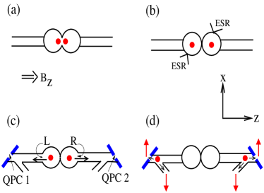
More precisely, the system we will consider consists of two coupled quantum dots in a parallel magnetic field which are connected to two quantum point contacts (QPCs) via empty quantum channels, see Fig. 1. The double dot is initially occupied by two electrons (Fig. 1(a)) in their lowest energy state, the singlet state singlet . The gate between the two dots is then adiabatically closed, so that the electrons become separated and one dot is occupied by an electron with spin-up and the other by one with spin-down. The two spins do not interact anymore and are independently rotated by ESR fields (Fig. 1(b)). (The coherent rotation of spins by ESR fields is the equivalent of the rotation of the polarizers in optical Bell experiments aspe82 .) After spin rotation, the electrons are emitted into the quantum channels by opening gates L and R (Fig. 1(c)) and scattered at quantum point contacts QPC 1 and QPC 2. In a parallel magnetic field and for conductances these QPC’s are spin-selective poto02 , transmitting electrons with spin-up and reflecting those with spin-down (Fig. 1(d)). The transmitted and reflected electrons are separately detected in the four exits.
As Guehne et al. have recently discussed gueh02 , the optimal entanglement witness operator for detection of a singlet, (where denotes the matrix partial transpose and ), can be achieved by having the two electron spins simultaneously rotated either by around the -axis in spin space, around the axis, or leaving them unrotated. One measures the probability of anticoincidences (spins opposite) for the -rotation cases, and the probability of coincidences averaged over the other two settings. Then, the value of the entanglement witness measurement is given by . While this prescription is well known in the quantum information community, it has not been well appreciated in the electron physics community that these more precise, quantitative measures of entanglement are no more difficult than the “standard” Bell test clau69 .
We now analyze the dynamics of the two spins from the moment they are separated, each occupying one of the two dots, until both have been detected in one of the four exits. Using a density matrix approach, this process is represented by the time evolution of a set of quantum states due to coherent (ESR) and incoherent (dissipative and tunnel) couplings. The incoherent processes are incorporated by phenomenological decay rates and we estimate these rates using experimentally measured values (for quantum dots) and Fermi’s golden rule (for quantum channels). By solving the resulting set of equations the probabilities to simultaneously detect pairs of spins (,) with are obtained. Our main conclusion is that detection of entanglement in this double dot turnstile via an entanglement witness measurement, including Bell tests, is feasible under realistic circumstances. We first present the model, followed by a discussion of the results.
In the setup as depicted in Fig. 1 each electron is assumed to be either in a dot, in a channel or detected. This leads to a set of 36 possible quantum states represented by a 3636 density matrix . This set consists of all possible combinations , with and indicating the position (dot, channel and exit) and spin direction along of the electron which started out in the left dot, and and representing the position and spin direction of the electron which started out in the right dot channel . The time evolution of the density matrix elements is given by the master equations
| (1a) | |||||
| (1b) | |||||
for . The Hamiltonian describes the coherent evolution of the system due to the ESR fields and is given by, for two oscillating magnetic fields and applied to the left and right dots respectively sin ,
| (2) |
Here is a diagonal matrix containing the
energies () of each state, the
electron g-factor, the Bohr magneton and
a 3636 matrix with elements
for each pair of states
that are coupled by the oscillating field and zero
otherwise. For example, for the four states in which both
electrons are in a dot , ,
, (labelled 1, 2, 3, 4) the
energies are given by , and in terms of
the single-particle energies and and the
charging energy , and the matrix elements
for pairs (1,3), (3,1), (2,4),
(4,2) and zero otherwise. The parameter , with , represents the relative reduction of the field which is
applied to one dot at the position of the spin in the other dot.
This is discussed in more detail towards the end of this paper.
Turning to the transition rates (from state to ) in Eqs. (1), we distinguish between two kinds of transitions: (1) spin-flip transitions between two states that differ by the direction of one spin only and (2) tunneling (without spin-flip) between states that involve adjacent parts of the system, i.e. from dot to channel and from channel to exit. The latter are externally controlled by opening and closing gates. The former are modeled by the phenomenological rate with for spin flips in a dot or channel. Here the s depend on the Zeeman energy and temperature via detailed balance , so that
| (3) |
Finally, the spin decoherence rates in Eqs. (1b) for states and such that either or or both correspond to a state in which at least one electron is located in a channel and none in the exits, are given by
| (4) |
The coherence between state and thus not only depends on the intrinsic spin decoherence time , but is also reduced by tunneling processes from dot to channel and from channel to exit enge02 .
With the above ingredients, the coupled equations (1) can be solved analytically. Details of this calculation are presented elsewhere blaa04 . The solution obtained is exact under 3 assumptions: 1) the time evolution during ESR in the dots is decoupled from the time evolution in the channels and exits. Physically, this means that no tunneling occurs out of the dots during the ESR rotations. 2) Once the electrons are in a channel they cannot tunnel back into the dots, i.e. back reflection is neglected. 3) Once the electrons are in one of the exits they are immediately absorbed. With these realistic assumptions, the master equations are solved in 3 steps: the time evolution during ESR applied to the left and right dots and the time evolution after the gates to the quantum channels have been opened. During each step only part of the quantum states are evolving in time, while the others remain unchanged. This simplifies the procedure to obtain an analytical solution.
In order to characterize the entanglement of the two electron spins, we are interested in the time evolution of the probabilities that both spins have been detected. Implementing the optimal entanglement witness then consists of measuring (), the cumulative probabilities that a coincidence (anticoincidence) count has happened at time , for the spin rotations as discussed above. These probabilities depend on the angles of rotation during the two ESR processes, on the tunneling rates , and on the and times in the dots and channels. The full expressions are given in Ref blaa04 .
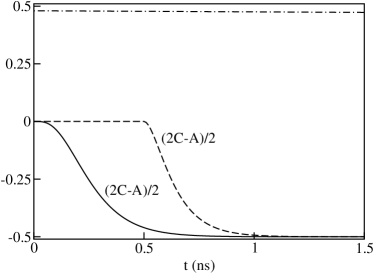
Fig. 2 shows the probability for the spin rotations discussed before as a function of time , where corresponds to the moment at which the gates to the channels are opened. It also shows the (very slight) decay of the off-diagonal matrix element which describes the coherence of the entangled singlet pair in the isolated double dot, i.e. in the absence of tunnel coupling to the channels ( for the fully coherent pair). By comparing this matrix element with the entanglement condition , the critical amount of decoherence above which the experiment does not work anymore can be estimated. For the (realistic) parameters used in Fig. 2 the decoherence at the time when the probability that both spins have been detected has approached 100% (at ns) is sufficiently small for detection of entanglement to be possible.
Finally, we briefly discuss the estimation of the and times. In order for the entanglement detection to be successful, spin coherence of each detected pair must be preserved from the moment of creation of the singlet in the double dot until the two electrons have been detected. It is thus essential to investigate the time scales and for decoherence and dissipative processes in the dot and channels. Starting with the dot, for a single spin has recently been experimentally measured and found to be ms at elze04 . The spin decoherence time has not been measured yet for a single spin in a quantum dot but is expected to lie between 100 ns s kikk99 ; khae03 . In the quantum channels we have estimated a lower bound for by calculating the inverse relaxation rate due to emission or absorption of a phonon (in the absence of a spin-flip relaxation ) using Fermi’s golden rule. We obtain s for B=8T and = 100 mK, with the channel length.
In order to estimate we apply the calculations in Ref. khae03 for the decoherence time of a single spin in a quantum dot due to hyperfine interaction shen04 to a quantum channel. This results, just as for a dot, in the bounds , with the number of nuclei in the channel and the mean hyperfine interaction strength. Using in a channel of length 1m and eV for GaAs we find ns.
We see that in the dots the decoherence time is the limiting time scale: separating the entangled pair and rotation by ESR fields has to happen within . The time it takes to adiabatically close the barrier between the two dots can be obtained from the requirement , where is the maximum angular velocity of the dot eigenstate during the closing and the minimum Bohr frequency mess58 . Modeling the quantum dots with a parabolic confining potential , we estimate with the singlet-triplet energy splitting burk99 . Assuming ESR fields of 1 mT, the rotation time ns (for rotations by ), so provided 100 ns both separation of the pair and two rotations can be performed within the decoherence time . For quantum channels that are 0.1 m long the travel time of an electron, assuming ballistic transport, is ps, which is less than both and . The arrival of consecutive spin pairs at the QPC’s is then separated by s, which corresponds to a current signal ps. This is observable and forms a more transparent way of detection than noise measurements. By measuring the current in the four exits in real time vand04 for repeated runs of the experiment, the coincidence probabilities and can be determined.
Let us finish with some remarks on the detectors and the ESR rotations. It has recently been demonstrated that a QPC which is set to transmit only a single mode becomes spin-polarized in a parallel magnetic field poto02 : it only transmits electrons with spin-up and reflects those with spin-down, which is due to the fact that the spin-down electrons in the Fermi sea see a higher barrier at the QPC than the spin-up electrons. This is also true for a single electron that arrives at the QPC in an otherwise empty channel, provided that the electron has not relaxed to the bottom of its energy band. In the latter case, the QPC barrier height for a spin-up and a spin-down electron is the same. As long as the time the electron spends in the channel is sufficiently less than , the QPC detectors are able to distinguish between the two spin directions detectors .
Finally, turning to the spin rotations, currently-available ESR fields cannot be applied to one of two adjacent dots only, as represented by the parameter in Eq. (2). It is therefore not possible to use each field to coherently rotate only one spin, as was done with polarizers in the analogous photon experiment aspe82 . It is, however, nevertheless possible - by using both ESR fields during each of the two rotation-intervals in the absence of exchange coupling between the two spins - to rotate both spins independently. Alternatively, one could use two well-separated additional dots, each of which is located between the double dot and a detector, to perform independent ESR rotations.
In conclusion, we have presented a scheme for detecting entanglement of electron spins in a double-quantum-dot turnstile. Using a carefully timed series of pulsed gate and ESR operations, pairs of entangled electron spins are separated and coherently manipulated in the quantum dots and subsequently detected at two spin-polarized QPC’s. We have analyzed the time scales for spin decoherence and relaxation and demonstrate that under realistic experimental conditions the evolution from creation to detection of each pair can be completed within the coherence time, thus allowing for a quantitative entanglement test to be performed. Moreover, due to the high level of external control over the dynamics, this setup can be used to produce pairs of entangled electrons on demand.
Stimulating discussions with L.P. Kouwenhoven, L.M.K. Vandersypen and B.M. Terhal are gratefully acknowledged. This work has been supported by the Stichting voor Fundamenteel Onderzoek der Materie (FOM), by the Netherlands Organisation for Scientific Research (NWO) and by the EU’s Human Potential Research Network under contract No. HPRN-CT-2002-00309 (“QUACS”). DPDV is supported in part by the NSA and ARDA through ARO contract numbers W911NF-04-C-0098 and DAAD19-01-C-0056.
References
- (1) G.B. Lesovik et al., Eur. Phys. J. B 24, 287 (2001); P. Recher, E.V. Sukhorukov, and D. Loss, Phys. Rev. B 63, 165314 (2001); P. Recher and D. Loss, ibid. 65, 165327 (2002); C. Bena et al., Phys. Rev. Lett. 89, 037901 (2002).
- (2) P. Samuelsson, E.V. Sukhorukov and M. Buttiker, Phys. Rev. Lett. 91, 157002 (2003).
- (3) D. Loss and E.V. Sukhorukov, Phys. Rev. Lett. 84, 1035 (2000); G. Burkard, D. Loss and E.V. Sukhorukov, Phys. Rev. B 61, R16303 (2000); W.D. Oliver, F. Yamaguchi and Y. Yamamoto, Phys. Rev. Lett. 88, 037901 (2002); J.C. Egues et al., in Quantum Noise in Mesoscopic Systems, edited by Yu. V. Nazarov (Kluwer Academic Publishers, The Netherlands, 2003); X. Hu and S. Das Sarma, Phys. Rev. B 69, 115312 (2004).
- (4) A.T. Costa, Jr., and S. Bose, Phys. Rev. Lett. 87, 277901 (2001).
- (5) C.W.J. Beenakker et al., Phys. Rev. Lett. 91, 147901 (2003); P. Samuelsson, E.V. Sukhorukov, and M. Buttiker, ibid. 92, 026805 (2004).
- (6) N.M. Chtchelkatchev et al., Phys. Rev. B 66, 161320(R) (2002).
- (7) A. Aspect, P. Grangier and G. Roger, Phys. Rev. Lett. 49, 91 (1982).
- (8) B.M. Terhal, J. of Theor. Comput. Sci. 287, 313 (2002).
- (9) (a) Controlling the number of electrons in a lateral quantum dot down to zero has recently been achieved, see M. Ciorga et al., Phys. Rev. B 61, R16315 (2000); J.M. Elzerman et al., ibid. 67, 161308(R) (2003); R.M. Potok et al., Phys. Rev. Lett. 91, 016802 (2003). (b) Up to parallel magnetic fields of at least 12 T the singlet state is the ground state of a doubly-occupied quantum dot, see R. Hanson et al., Phys. Rev. B 70, 241304 (2004).
- (10) R.M. Potok et al., Phys. Rev. Lett. 89, 266602 (2002).
- (11) O. Gühne et al., Phys. Rev. A 66, 062305 (2002).
- (12) See e.g. J.F. Clauser et al., Phys. Rev. Lett. 23, 880 (1969).
- (13) The states labeled by and do not refer to individual quantum states in the channels and exits, but are defined as the set of all channel modes resp. of all quantum states in the exits. They thus describe the probability of an electron occupying any one of these states.
- (14) For rotations around , oscillating magnetic fields and are used.
- (15) See Sec. II C of H.A. Engel and D. Loss, Phys. Rev. B 65, 195321 (2002).
- (16) M. Blaauboer, J. Math. Phys. 46, 083518 (2005).
- (17) J.M. Elzerman et al., Nature 430, 431 (2004).
- (18) See J. Kikkawa and D.D. Awschalom, Nature 397, 139 (1999) (lower bound).
- (19) A. Khaetskii, D. Loss and L. Glazman, Phys. Rev. B 67, 195329 (2003).
- (20) Relaxation rates including both phonons and a spin flip are smaller than those due to phonons only, see S.I. Erlingsson and Yu. V. Nazarov, Phys. Rev. B 66, 155327 (2002).
- (21) For T hyperfine coupling is expected to be the dominant source of decoherence, see N. Shenvi et al., Phys. Rev. B 71, 144419 (2005).
- (22) A. Messiah, Quantum Mechanics, (Dover, New York, 1958), Ch. 7.
- (23) G. Burkard, D. Loss and D.P. DiVincenzo, Phys. Rev. B 59, 2070 (1999).
- (24) L.M.K. Vandersypen et al., Appl. Phys. Lett. 85, 4394 (2004).
- (25) Alternatively, additional dots could be used as spin detectors.