Escape configuration lattice near the nematic-isotropic transition: Tilt analogue of blue phases
Abstract
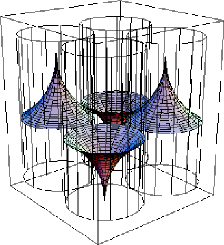
We predict the possible existence of a new phase of liquid crystals near the nematic-isotropic () transition. This phase is an achiral, tilt-analogue of the blue phase and is composed of a lattice of double-tilt, escape-configuration cylinders. We discuss the structure and the stability of this phase and provide an estimate of the lattice parameter.
pacs:
61.30.-v,64.70.Md,61.30.Dk,61.30.Jf,61.30.MpLiquid crystals are soft materials; this makes the existence of phases such as the blue phases de-Gennes:93 ; Meiboom:81 , the twist grain boundary phases Renn:88 ; Goodby:88 and the smectic blue phases DiDonna:03 ; Pansu:01 possible. In this paper we explore the possible existence of a new phase of liquid crystals intervening the nematic () and the isotropic () phases. The proposed phase is composed of escape-configuration cylinders Mayer:73 ; Cladis:72 , and can be thought of as an achiral, tilt analogue of blue phases (see Fig.1). Blue phases are composed of double-twist cylinders and intervene between the cholesteric and the isotropic phases. Interestingly, the stability of double-twist cylinders forming blue phases is not solely due to the chirality of molecules. Double-twist cylinders are favored over the simple cholesteric with twist along a single axis if the coefficient of the saddle-splay deformation term in the elastic free energy is positive Meiboom:81 ; de-Gennes:93 . The saddle-splay deformation (see (2)) corresponds to a surface-like term in the free energy (it is a total divergence and integrates to the bounding surface by Gauss’s theorem). Therefore blue phases necessarily require the presence of interfaces for their stability. The gaps between the double twist cylinders in the cubic blue phases are believed to be filled with higher symmetry, lower order isotropic materialde-Gennes:93 .
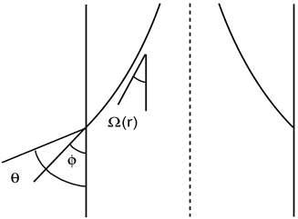
For a two-dimensional nematic confined within a circle, and subject to the boundary condition that the nematic director is radial at the circumference, it is a topological imperative that the director field inside the circle have point singularities (disclinations) with a total charge of +1. However, a similar topological requirement does not apply to a three-dimensional nematic confined within a cylindrical capillary with radial boundary conditions. The line singularity can be removed by the escape of the nematic director into the third dimension Mayer:73 ; Cladis:72 . The singular disclination line is stable if , where is the radius of the capillary, and is a microscopic cut-off (see (1) below). Clearly, escape-configurations are favored over configurations with topological singularities for reasonable capillary radii unless the splay elastic constant is unusually small. The director field in the escape-configuration cylinders (Fig.2) is tilted with respect to the axis of the cylinder, and has splay as well as bend deformation. This tilt of the director can be resolved in two mutually orthogonal directions in a plane perpendicular to the axis of the cylinder; they are double-tilt cylinders. These cylinders clearly have a non-zero saddle-splay deformation: the two principal curvatures of the nematic director field at any point in the cylinder have opposite signs.
Can a phase composed of the double-tilt cylinders exist near the nematic-isotropic () transition for reasonable values of parameters? In what follows we answer this question in the affirmative, and propose a possible candidate for such a phase. In the spirit of the “low chirality” analysis of blue phases Meiboom:81 ; de-Gennes:93 , we use the continuum description of nematics and ignore the effects of thermal fluctuations. As is the case with the low chirality theory, the theory presented in this letter is not a theory of phase transitions based upon an order parameter description.
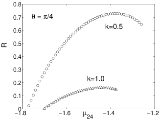
Our results are summarized in Figs.(1, 4 and 5). The lattice depicted schematically in Fig.(1) is stabilized by the competition between () the saddle-splay deformation (2); and () the bulk nematic deformation (1), the nematic-isotropic interface energy (3), and the weak-anchoring energy at the interface (4). In the structure proposed in this paper, the gaps between the cylinders are filled up with the high symmetry, low order isotropic material. Notice that the lattice shown in Fig.(1) is an antiferroelectric lattice: neighboring cylinders have opposite escape directions to maintain the continuity of the director field across the planes joining the cylinder axes. Each double-tilt cylinder can be characterized by the direction of escape (up or down), and is a polar object even if the nematogenic molecules are not polar. Fig.(4) shows that the proposed phase has a small region of stability near the transition temperature in the space of the dimensionless parameters , the relative strength of the coefficient of the saddle-splay term to the typical coefficient of the bulk Frank free energy, and , the relative strength of the coefficient of the nematic-isotropic interfacial tension to the coefficient of anchoring energy at the interface. In the case of cubic blue phases, the pitch of the cholesteric provides a natural length scale, and the nematic director twists through from the center of the double-twist cylinder to its boundary. This ensures that the director is continuous across neighboring double-twist cylinders. In the present problem, there is no “natural” length scale at the lowest order of the continuum description that we employ. We therefore calculate the radius of double-tilt cylinders by solving the free boundary condition that arises naturally from the variational problem of minimizing the total free energy (see (8)). Fig.(5) shows the variation of the radius of the cylinder (which is half the lattice parameter) with for various values of .
In order to derive these results we begin by listing the contributions to the total free energy. The bulk Frank free energy density is
| (1) | |||||
where and are respectively the splay, twist, and bend elastic constants. In what follows, we use the “one-constant” approximation , which is indeed a reasonable approximation near the nematic-isotropic transition temperature footnote2 .
In addition to the bulk contribution, we have the surface-like saddle-splay elastic free energy density
| (2) |
We note that the sign of is not dictated by stability conditions.
The free energy associated with the nematic-isotropic interface is composed of two parts, the usual surface tension part
| (3) |
and the Rapini-Papoular Rapini:69 “weak anchoring energy”
| (4) |
where is the preferred angle of the nematic director at the interface (see Fig.2), and the integrals are over the interface. Experimentally, values of as large as about have been reported Faetti-Palleschi:84 . The spontaneous nonzero tilt of the director at the interface has its origin Barbero:86 in the order electric polarization Prost:77 arising from the gradient of the nematic order parameter across the nematic-isotropic interface. Since the present model is not based upon an order parameter description, it is sufficient for our purpose to recognize that is nonzero and use (4) for the energy cost of deviations from the angle at the interface.
We now discuss the energetics of a single escape-configuration cylinder at the transition (at the transition point, there is no free energy difference between the nematic in the escape cylinders and the isotropic material filling in the gaps between them). The total free energy for our model is
| (5) |
where , and .
We parameterize the nematic director as in cylindrical polar coordinates, where is the angle made by the director with the axis of the cylinder (see Fig.2 ). The free energy per unit length of the cylinder of radius is
| (6) | |||||
where , and the length along the cylinder axis is unity. The Euler-Lagrange equation reads
| (7) |
The variational problem of minimizing the total free energy leads to the free boundary condition
| (8) |
where is the radius of the escape cylinder. This condition which ensures torque balance at the boundary of the escape cylinders picks out the radius of the escape cylinders and hence the lattice parameter.
We recognize that the angle made by the nematic director at the interface is not necessarily equal to the angle preferred by the anchoring energy. Therefore, we first solve Eq.(7) subject to the condition that the nematic director makes an angle at the interface, and then proceed to minimize the total free energy with respect to (see Fig. 3).
The solution to the Euler-Lagrange equation is Doane:92
| (9) |
The free boundary condition (8) relates the radius of the cylinder to the angle at the boundary of the cylinder, so that
| (10) |
where is a length, , with . Substituting the expression (10) for the radius in yields the energy per unit length (measured in units of ) of a single double-tilt cylinder of radius :
| (11) |
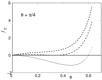
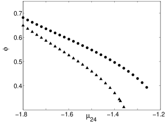
where , and we have defined . We numerically minimize the free energy (11) with respect to to find the dependence of on (Fig.(5)), and of on (Fig.(6)).
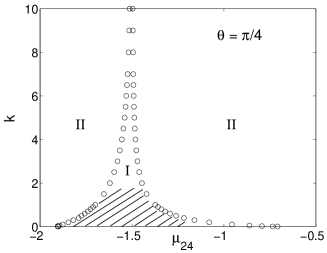
We now estimate the approximate value of the radius at which double-tilt cylinders are energetically favored over the uniform, undistorted nematic at the transition. With and cm; the radius of the double-tilt cylinders is about m for , whereas it is about m for . It is important to note that the continuum description that we have employed fails at very small radii of the cylinders. The transition is first order in nature, and the order parameter coherence length is of the order of molecular dimensions (see de-Gennes:93 ). The cylinder sizes estimated above (for a reasonable range of parameter values) are about ten times the order parameter coherence length. From Fig.(5) we expect the continuum description to be valid within the shaded region indicated in Fig.(4).
Fig.(4) depicts the range of stability (labelled I) of the double-tilt cylinders in the plane. In the region labelled II on the right- hand side of the spike in Fig.(4) the gain in energy from the saddle-splay term is not enough to overcome the energy costs from the Frank free energy, the surface tension and the anchoring energy terms. On the left hand side of the stable spike in figure 4, as the signed value of decreases, and at the boundary approaches in order to gain energy from the saddle-splay term (see Fig.(6)). However, the torque balance condition (8) at the boundary forces the relation (10), thereby reducing the radius of the cylinders (see Fig.(5)). Equation (10) implies that the radius of the cylinders goes to zero for . Finally we discuss the possibility of forming lattices of escape cylinders. For a two dimensional lattice, continuity of the director field across the planes connecting the axes of neighboring double-tilt cylinders enforces the condition that these have opposite escape directions. Clearly, the triangular lattice is frustrated. The proposed square lattice is antiferroelectric.
Having demonstrated the feasibility of forming a two-dimensional lattice of double-tilt cylinders for reasonable parameter values, we note the following: (i) it may be possible to construct three dimensional lattices out of escape configurations which are not necessarily cylindrical in shape. We have explored the possibility of forming three dimensional structures of right circular double-tilt cylinders. Cubic lattices (BCC and FCC) can be formed if the angle . For all other angles we find that matching the director field at the boundaries of neighboring cylinders introduces additional distortions in the director field of the double-tilt cylinders. Energetics of these three dimensional structures is beyond the scope of this paper. (ii) It is possible to construct lattices composed of hyperbolic escape configurations (which correspond to escaped -1 disclinations), and (iii) the double-tilt cylinders can form a molten line liquid analogous to the molten flux line liquidsNelson:88 and the chiral line liquidsKamien:93 ; Navailles:98 of liquid crystals. In conclusion we have clearly demonstrated that the structure proposed in this paper has a lower free energy than the nematic as well as the isotropic phase near the transition. Whereas we do not claim that this structure is the global minimum of the free energy, our demonstration strongly suggests the possibility of lattices composed of double-twist cylinders.
Freeze fracture electron microscopy of pure compounds exhibiting a broad transition may be a possible way to search for the proposed phase, since the length scale involved ( to ) is inaccessible to other experimental probes. We urge experimentalists to look closely for signatures of such structures near the transition.
We thank T. C. Lubensky for discussions, J. V. Selinger, G. S. Ranganath, A. J. Levine and J. P. Sethna for useful suggestions. BC thanks A. J. Levine for financial support. YH thanks NSF grant no. DMR-0209256 for partial support.
References
- (1) Now at Department of Physics, Harvard University, Cambridge, MA 02138.
- (2) P. G. de-Gennes, and J. Prost The physics of Liquid Crystals, Clarendon Press, Oxford, 1993; and references therein.
- (3) S. Meiboom, J. P. Sethna, P. W. Anderson and W. F. Brinkman, Phys. Rev. Lett. 46, 1216 (1981).
- (4) S. R. Renn and T. C. Lubensky, Phys. Rev. A 38, 2132 (1988).
- (5) J. Goodby, M. A. Waugh, S. M. Stein, E. Chin, R. Pindak, and J. S. Patel, Nature 337, 449 (1988); J. Am. Chem. Soc. 111, 8119 (1989).
- (6) B. A. DiDonna and R. Kamien, Phys. Rev. E 68, 041703 (2003).
- (7) E. Grelet, B. Pansu, M-H. Li, and H. T. Nguyen, Phys. Rev. Lett. 86, 3791 (2001).
- (8) R. B. Mayer, Phil. Mag. 27, 405 (1973).
- (9) P. Cladis and M. Kleman, J. Phys. (Paris) 33, 591 (1972).
- (10) The “one-constant” approximation is valid in as much as the contribution proportional to the square of the nematic order parameter does not contribute significantly to and near the transition. See de-Gennes:93 above.
- (11) A. Rapini and M. Papoular, J. Phys. (Paris) Colloq. 30, C4-54 (1969).
- (12) S. Faetti and V. Palleschi, Phys Rev. A 30, 3241 (1984); J. Phys. (Paris) Lett. 45, L313 (1984).
- (13) G. Barbero, I. Dozov, J. F. Palierne, and G. Durand, Phys. Rev. Lett. 56, 2056 (1986).
- (14) J. Prost and J. P. Marcerou, J. Phys (Paris) 38, 315 (1977).
- (15) G. P. Crawford, D. W. Allender and W. Doane, Phys. Rev. A 45, 8693 (1992).
- (16) D. R. Nelson, Phys. Rev. Lett. 60, 1973 (1988); D. R. Nelson and H. S. Seung, Phys. Rev. B, 39, 9153 (1989).
- (17) R. D. Kamien and T. C. Lubensky, J. Phys. I France 3, 2131 (1993).
- (18) L. Navailles, B. Pansu, L. Gorre-Tallini, and H. T. Nguyen, Phys. Rev. Lett. 81, 4168 (1998).