Electron spin interferometry using a semiconductor ring structure
Abstract
A ring structure fabricated from GaAs is used to achieve interference of the net spin polarization of conduction band electrons. Optically polarized spins are split into two packets by passing through two arms of the ring in the diffusive transport regime. Optical pumping with circularly polarized light on one arm establishes dynamic nuclear polarization which acts as a local effective magnetic field on electron spins due to the hyperfine interaction. This local field causes one spin packet to precess faster than the other, thereby controlling the spin interference when the two packets are combined.
pacs:
85.75.-d, 78.47.+pRecent progress in electron spin manipulation using non-magnetic semiconductors includes the ultrafast all-optical scheme Gupta:2001 , electrical control using g-factor engineering in parabolic Salis:2001 ; Kato:2003 and coupled quantum wells Poggio:2004 , the strain induced spin-orbit interaction Kato:2004 ; Kato:2005 , and the spin Hall effect Kato:2006 , demonstrating the broad scope of techniques that can be achieved using state-of-the-art semiconductor engineering. The flexibility offered by semiconductor spintronics Wolf:2001 ; Semiconductor:2002 ; Zutic:2004 is anticipated to lead to novel devices and may eventually become useful for quantum information processing. Another advantage offered by spin systems in semiconductors is their long coherence times. For example, conduction electron spins in -type GaAs can have a coherence time exceeding 100 ns and can be transported over distances exceeding 100 m. Kikkawa:1998 ; Kikkawa:1999 In contrast, the coherence time of the orbital part of the electron wave function is at most a few picoseconds even in high-mobility two dimensional systems. Here, we demonstrate a device which takes advantage of the long coherence time of the carrier spin system. A ring structure is fabricated from -GaAs in which electron spins are optically initialized, split into two different paths, and recombined on the opposite side. Local nuclear polarization gives rise to an additional spin precession phase in one path, causing constructive and destructive interference between the two spin packets.
On a semi-insulating (001) GaAs substrate, 2 m of undoped Al0.4Ga0.6As and 2 m of -GaAs (Si-doped for cm are grown by molecular beam epitaxy. The interferometer is fabricated from the -GaAs film, while the AlGaAs film underneath acts as an etch stop layer. The substrate is polished to 200 m prior to processing, and the ring structure [Fig. 1(a)] is defined by standard photolithography techniques. The mesa is formed by selective spray etching Tanobe:1992 with a mixture of one part NH4OH (30%) to 30 parts H2O2 (35%), and a second photolithography step is performed to define the contact areas. The metal layers for the contacts are deposited by electron beam evaporation in the following order: Ni (5 nm) / Ge (25 nm) / Au (65 nm) / Ni (20 nm) / Au (200 nm). The sample is annealed at 420oC for one minute to form ohmic contacts, and a third photolithography step defines a square window on the back side of the substrate. Selective spray etching is used again to etch the substrate from the back, forming a membrane to allow optical transmission experiments. The device has a two-contact resistance of 6.2 k at a temperature K.
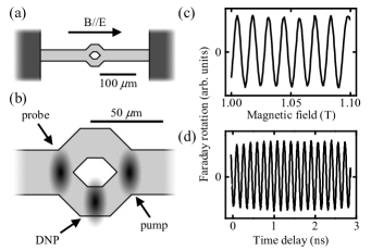
To monitor the electron spin dynamics in the device, we employ time-resolved Faraday rotation Crooker:1995 ; Crooker:1997 in the Voigt geometry with the sample growth axis parallel to the optical axis. A mode-locked titanium sapphire laser produces 150 fs pulses at a repetition frequency of 76 MHz and its wavelength is tuned to 818 nm to address the band gap of GaAs. A circularly polarized pump pulse injects spin polarized electrons, and the Faraday rotation of a linearly polarized probe pulse measures the electron spin component along the laser propagation direction at a time delay t. The laser beams are focused to a spot size of 30 m, and the average laser powers are 500 W and 60 W for the pump beam and the probe beam, respectively. The circular polarization of the pump beam is modulated with a photoelastic modulator at 50 kHz for lock-in detection and t is controlled with a mechanical delay line. Measurements are conducted at K where the longest electron spin lifetimes have been observed. Kikkawa:1998
We focus the pump beam to the right side of the ring to generate electron spin polarization, while the probe beam detects the spins at the left side of the ring [Fig. 1(b)]. A positive voltage is applied to the contact on the left while the right contact is grounded, establishing an electric field which causes the spins to drift across the structure and into the probe spot. In general, the Faraday rotation signal can be described as
| (1) |
where is the amplitude, is an integer specifying successive pulses, ns is the repetition time of the laser, is the spin lifetime, and is the electron Larmor frequency, is the effective electron g factor, is the Bohr magneton, is the applied magnetic field, and is the Planck constant. Kikkawa:1998 In order to simplify the data analysis, the voltage is chosen such that only the pulse contributes to the signal. This is possible as the spin packets from successive pulses are spatially well separated after if a large enough electric field is applied. Kikkawa:1999 In Fig. 1 (c), the magnetic field dependence of the Faraday rotation around T with a bias voltage of 3.5 V is shown. The absence of other harmonic components indicates that pulses with are not contributing to the signal since the spins generated from earlier pulses have drifted past the probe spot. In Fig. 1 (d), Faraday rotation is plotted as a function of . We see no abrupt jump at ns, showing that there is no contribution from the pulse. This is expected as the pump and the probe spots are spatially separated. The frequency of the spin precession signal is used to extract the electron g-factor, and gives . We also note that the voltage has been tuned such that the spin precession signal has uniform amplitude throughout the available range of t, meaning that the center of the spin packet goes through the center of the probe spot at around ns. The strain-induced effective magnetic field Kato:2004 plays a negligible role at these large applied magnetic fields.
In order to establish a phase difference between the two paths, optically pumped dynamic nuclear polarization (DNP) is utilized. A circularly polarized third beam with an average power of 5 mW is derived from the same laser and is focused on the lower arm [Fig. 1 (b)]. A slight tilt of the sample causes diffraction of the DNP beam and results in some electron spin polarization along . A part of the electron spin angular momentum is transferred to nuclear spins, establishing DNP along the applied magnetic field which acts as an additional effective magnetic field for the electron spins through the contact hyperfine interaction. Optical:1984 ; Salis:2002 In this manner, the electrons traveling through the lower arm gain an additional phase to their spin precession. After the two packets have recombined, the expected time-resolved Faraday rotation is
| (2) |
where
| (3) |
and
| (4) |
Here, and are the amplitudes of the spin packets in the upper and the lower arms, respectively, is the phase difference between the two packets, and lastly, and are the amplitude and the phase, respectively, of the combined packet. As is varied, a change in the amplitude of the spin precession signal should occur as a result of the interference term .
We initialize the device by waiting for 30 minutes at T with the DNP beam on the sample and the bias voltage set to 0 V. The voltage is turned off in an effort to localize the nuclear polarization, while the magnetic field is applied to increase the nuclear polarization. Kikkawa:2000 After the nuclear polarization has built up, the DNP beam is blocked, the voltage is set to 3.5 V, and measurements of Faraday rotation as a function of t are made repeatedly [Fig. 2 (a)]. Since the DNP beam is turned off, the nuclear spins begin to relax over a timescale of 30 minutes and reduce the phase difference between the two paths. As a consequence, the recombined electron spin polarization at the left side of the ring cycles through constructive and destructive interferences, which manifests as an oscillation in the amplitude of the spin precession signal. Two and a half oscillations are observed in 1500 s, corresponding to a difference in an average effective magnetic field of 28 mT between the two arms.
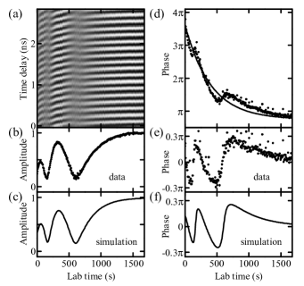
In order to quantitatively characterize the interference, we fit individual time-resolved Faraday rotation data with . The parameters and obtained from the fits are plotted as a function of lab time in Fig. 2(b) and (d), respectively. The amplitude does not dip down to zero, which is expected if the spin packets from the two arms do not have equal amplitudes. Additionally, the oscillation amplitude increases with lab time, which we attribute to the decrease in signal at early times due to inhomogeneous nuclear polarization that extends to both arms. Diffusion of spin polarized electrons generated by the DNP beam can result in such nuclear polarization, which in turn causes the electron spins used for the interference to dephase. The dephasing will diminish as the nuclear spins depolarize, and this will increase the amplitude of the spin precession signal. This is consistent with the behavior of the phase, which shows an exponential decay with small oscillations superimposed. This decay can be explained by changes in as a result of nuclear polarization in both arms.
Assuming that both the amplitude and the phase difference recover with the nuclear spin relaxation time , the amplitude of each packet and the phase difference are modeled as
| (5) |
| (6) |
and
| (7) |
Here, and are the fractions of upper and lower arms contributing to signal, respectively, and represent the portions of the signal which have been reduced due to inhomogeneous nuclear polarization, and is the phase difference due to the nuclear polarization between the two paths at time s. The lab-time dependence of the amplitude and phase of the combined spin packet are simulated from Eq. (3) and (4). The model gives good agreement to data with , , , , and s [Fig. 2 (c)]. For the analysis of the phase, we have subtracted an exponentially decaying component and an offset given by with and s, which is shown as a solid line in Fig. 2 (d), and the data after subtraction is shown in Fig. 2 (e). The simulation of the lab-time dependence of the phase is obtained from the same set of parameters used in Fig. 2 (c), and is shown in Fig. 2 (f). A good agreement is seen between the data and the model for the phase as well.
The parameters obtained in the analysis allow us to infer the spatial extent of the nuclear spin polarization. gives a measure of the nuclear polarization in the upper arm, while gives a measure of that in the lower arm. The ratio of these two values is 2.5, indicative of significant nuclear polarization in the upper arm. This can be explained by electron spin diffusion, which has been seen to extend to 15 m in a similar system. Stephens:2003 In addition, suppression of nuclear spin polarization at the center of a laser spot has also been observed previously, Stephens:2004 and this may be playing a role in keeping this ratio to a relatively small value. There may also be nuclear polarization arising from electron spins excited in the upper arm by tails of the DNP beam.
We note that the interference we observed is of net spin polarization of the electrons, and is not quantum interference Engel:2000 ; Yau:2002 ; Koga:2004 in the sense that the orbital part of the electron wave function has decohered. We also note that the Aharonov-Bohm effect Aharonov:1959 ; Webb:1985 ; Timp:1987 is not expected here as the magnetic field is applied in the plane of the sample.
In summary, we have demonstrated electron spin interferometry using a semiconductor ring structure. It takes advantage of the long lifetime of spin polarization relative to charge coherence, and may find applications in detecting magnetic field gradients. The measurements also provide insights into the effect of nuclear polarization on electron spin dephasing.
We thank G. Salis and acknowledge support from the DARPA and the DMEA.
References
- (1) J. A. Gupta, R. Knobel, N. Samarth, and D. D. Awschalom, Science 292, 2458 (2001).
- (2) G. Salis, Y. Kato, K. Ensslin, D. C. Driscoll, A. C. Gossard, and D. D. Awschalom, Nature 414, 619 (2001).
- (3) Y. Kato, R. C. Myers, D. C. Driscoll, A. C. Gossard, J. Levy and D. D. Awschalom, Science 299, 1201 (2003).
- (4) M. Poggio, G. M. Steeves, R. C. Myers, N. P. Stern, A. C. Gossard, and D. D. Awschalom, Phys. Rev. B 70, 121305(R) (2004).
- (5) Y. Kato, R. C. Myers, A. C. Gossard, and D. D. Awschalom, Nature 427, 50 (2004).
- (6) Y. K. Kato, R. C. Myers, A. C. Gossard, and D. D. Awschalom, Phys. Rev. Lett. 93, 176601 (2004).
- (7) Y. K. Kato, R. C. Myers, A. C. Gossard, and D. D. Awschalom, Science 306, 1910 (2004).
- (8) S. A. Wolf, D. D. Awschalom, R. A. Buhrman, J. M. Daughton, S. von Molnar, M. L. Roukes, A. Y. Chtchelkanova, and D. M. Treger, Science 294, 1488 (2001).
- (9) Semiconductor Spintronics and Quantum Computation, edited by D. D. Awschalom, D. Loss, and N. Samarth (Springer-Verlag, Berlin, 2002).
- (10) I. Zutic, J. Fabian, and S. Das Sarma, Rev. Mod. Phys. 76, 323 (2004).
- (11) J. M. Kikkawa and D. D. Awschalom, Phys. Rev. Lett. 80, 4313 (1998).
- (12) J. M. Kikkawa and D. D. Awschalom, Nature 397, 139 (1999).
- (13) H. Tanobe, F. Koyama, and K. Iga, Jpn. J. Appl. Phys. 31, 1597 (1992).
- (14) S. A. Crooker, D. D. Awschalom, and N. Samarth, IEEE J. Select. Topics Quantum Electron. 1, 1082 (1995).
- (15) S. A. Crooker, D. D. Awschalom, J. J. Baumberg, F. Flack and N. Samarth, Phys. Rev. B 56, 7574 (1997).
- (16) Optical Orientation, edited by F. Meier and B. P. Zakharchenya (Elsevier, Amsterdam, 1984).
- (17) G. Salis, D. D. Awschalom, Y. Ohno, and H. Ohno, Phys. Rev. B 64,195304 (2001).
- (18) J. M. Kikkawa and D. D. Awschalom, Science 287, 473 (2000).
- (19) J. Stephens, R. K. Kawakami, J. Berezovsky, M. Hanson, D. P. Shepherd, A. C. Gossard, and D. D. Awschalom, Phys. Rev. B 68, 41307(R) (2003).
- (20) J. Stephens, J. Berezovsky, R. K. Kawakami, A. C. Gossard, and D. D. Awschalom, Appl. Phys. Lett., 85, 1184 (2004).
- (21) H. A. Engel and D. Loss, Phys. Rev. B 62, 10238 (2000).
- (22) J. B. Yau, E. P. De Poortere, and M. Shayegan, Phys. Rev. Lett. 88, 146801 (2002).
- (23) T. Koga, J. Nitta, and M. van Veenhuizen, Phys. Rev. B 70, 161302(R) (2004).
- (24) Y. Aharonov and D. Bohm, Phys. Rev. 115, 485 (1959).
- (25) R. A. Webb, S. Washburn, C. Umbach, and R. A. Laibowitz, Phys. Rev. Lett. 54, 2996 (1985).
- (26) G. Timp, A. M. Chang, J. E. Cunningham, T. Y. Chang, P. Mankiewich, R. Behringer, and R. E. Howard, Phys. Rev. Lett. 58, 2814 (1987).